Please cite this article as: S. Masomi Kazraji, M. R. Feyzi, M. B. B. Sharifian, S. Tohidi, Sensorless Model Predictive Force Control with a Novel Weight Coefficients for 3-Phase 4-Switch Inverter Fed Linear Induction Motor Drives, International Journal of Engineering (IJE), IJE TRANSACTIONS C: Aspects Vol. 31, No. 9, (September 2018) 1536-1545
International Journal of Engineering
J o u r n a l H o m e p a g e : w w w . i j e . i rSensorless Model Predictive Force Control with a Novel Weight Coefficients for
3-Phase 4-Switch Inverter Fed Linear Induction Motor Drives
S. Masomi Kazraji*, M. R. Feyzi, M. B. B. Sharifian, S. Tohidi
Faculty of Electrical and Computer Engineering University of Tabriz, Tabriz, Iran
P A P E R I N F O
Paper history:
Received 27 December 2017 Received in revised form 14 April 2018 Accepted 26 April 2018
Keywords: Linear Induction Motor
Sensorless Model Predictive Force Control 4-switch Inverter
Weight Coefficient
A B S T R A C T
The sensorless model predictive force control (SMPFC) is a strong method for controlling the drives of three-phase 4(6)-switch inverter linear induction motors. This kind of inverter can be employed for the fault tolerant control in order to solve the problem of open/short circuit in the 6-switch inverters (B6). This paper propose a method for the SMPFC of a linear induction motor (LIM) fed by a 4-switch inverter fed along with DC-link voltage offset reduction. Simulations have been performed on several different LIMs in MATLAB software to determine the weight coefficients of stator flux and reduction of the capacitor voltage offset. Then, a relationship has been proposed for determining the weight coefficients in the cost function of the SMPFC. By using weight coefficients in the cost function, the B4 inverter voltage vectors are obtained for exact prediction. The balance of currents is improved by determining the appropriate value for the weight coefficient of the capacitor voltage offset reduction. Simulation results are provided for validation of the suggested control method.
doi: 10.5829/ije.2018.31.09c.09
NOMENCLATURE
r s R
R , Primary and Secondary resistances lls,llr Primary and Secondary leakage inductances
dr ds
, Primary and Secondary fluxes of d axe lm Magnetizing inductance
qr qs
, Primary and Secondary fluxes of q axe Lp Primary length
, Ts Pole pitch, sampling time p Pole number
k weight coefficient of the stator flux ids,idr Primary and Secondary currents of d axes
2
1, dc
dc U
U Capacitor voltages of the upper and lower DC-link iqs,iqr Primary and Secondary currents of q axe
g Cost function vl,vˆl Real and estimated linear speed
r s l
l , Primary and Secondary self-inductances uds,udr,uqs,uqr Primary and Secondary voltages of dq axes
Udc1, Udc2 capacitor voltages of DC-link. j index of the stator voltage vector
Ns number of switching Tdead dead time
1. INTRODUCTION1
Linear induction motors (LIMs) have several advantages such as need for no interface mechanical tools, low mechanical loss, high starting force, and a simple and strong structure. Such motors are used in automation and industrial applications, e.g. transportation, conveyor
*Corresponding Author Email: [email protected] (S. Masoumi Kazraji)
drives, electromagnetic launchers, and transfer of the containers in container terminals. Among different LIMs, single-side LIMs have received more attention due to their simpler structure and higher stability [1-3].
electromagnetic characteristics. In addition, existence of the traversal edge and longitudinal end effects creates difficulties in the modeling and controlling of such motors [4].
In recent years, inverters with 6 switches (B6) have been employed for applications such as motor drives. However, in some applications, further cost reduction for the structure of inverters has been proposed. In [1], a three-phase inverter with 4 switches (Figure 1) is suggested to minimize the costs of inverter, named as three-phase 4-switch inverter (B4). Also this inverter solves the problem of open circuit/short circuit in B6 inverters. The idea of applying 4-switch inverters for fault-tolerant control is valuable in some applications, including tensile systems [5-7]. 4-switch inverters have a number of flaws in comparison with B6 inverters. Their voltage utilization coefficient is half that of B6 inverters. Moreover, the capacitor voltage swings, interrupting the balance of motor currents. The fluctuations of capacitor increase the force ripple and reduce the inverter frequency.
Several methods have been proposed to reduce the effect of capacitor swings. A comparative space vector modulation method is introduced to compensate for the DC-link voltage ripple [8]. In [9], the capacitor voltage offset is neutralized by applying certain switching modes. Despite achieving a balance between the phase currents, this paper does not consider the flux and stator force. A closed-loop vector control method with a 4-switch inverter is examined [10]. In this method, speed loop is controlled with fuzzy logic controller. Also in [11], direct torque control is employed to control the flux and torque of induction motor with a 4-switch inverter. In this paper, the capacitors voltage is assumed to be constant. In fact, the one-phase current passes through DC-link voltage sources, resulting in fluctuations in the capacitor voltages.
Among the control methods, field-oriented control and direct force control (DFC) have received considerable attention for controlling LIM [12]. With development of fast microprocessors, the use of model predictive control (MPC) in the power electronic drives has become widespread [13, 14].
In predictive torque control, the complete model and the drives fed with the inverter are considered. A cost function is defined to reduce the torque and flux error in order to evaluate the effect of voltage vectors [15, 16].
The present paper is organized as follows: In section 2, dynamic models of LIM and three-phase 4-switch inverters are explained. In section 3, the predictive control method is expressed by removing the capacitor voltage. In sections 4 and 5, the weighting coefficients in the cost function and the results of simulation and real-time hardware-in-the-loop results are respectively analyzed. Finally, in section 6, the conclusions from the proposed control algorithm are provided.
C
b c a
C
T1 T2
T3 T4
Udc1
Udc2
idc1
idc2
ia
ib
ic
motor
T2 B4 Inverter
Figure 1. Circuit diagram of the induction motor fed by B4
inverter
2. MATHEMATICAL MODEL of LIM AND 4-SWITCH INVERTER
2. 1. Mathematical Model of LIM The relationships of the primary voltage in the synchronous dq reference frame are as follows [2, 13]:
ds dr
dsr ds s ds
dt d i i Q f R i R
u (1)
qs qs
s qs
dt d i R
u (2)
The relationships of the secondary voltage are:
ds dr
dr rqr r dr r dr
dt d i i Q f R i
R
u
(3
)
qr dr
r qr r qr
dt d i
R
u
(4
)
Q e Q f
Q
1 (5
)
r r m
r p
R L L
v L Q
/ ) (
/
(6
)
The electromagnetic force of the LIM is calculated as:
) (
2 2 3
ds qs qs ds
e i i
P
F
(7)
The primary and secondary currents dq for LIM are calculated by Equations (1)-(6):
2
21 1
Q f L Q f L L Q f L L
Q f L Q f L L i
m m
r m s
dr m
ds m r ds
(8)
m r s
qr m qs r qs
L L L
L L
i 2
(9)
2
21 1
Q f L Q f L L Q f L L
Q f L Q f L L i
m m
r m s
ds m
dr m s dr
m r s qs m qr s qr L L L L L i 2
(11)
f(Q) is utilized to take the end effect of the LIM into account in Equation (5).
2. 2. Mathematical Model of the 4-Switch Inverter B4 is a two-base inverter, as demonstrated in Figure 1. In order to have a better analysis, the inverter is implemented with ideal switches (T1-T4) [11]. This means that the basic switching modes b and c can be shown as binary variables Sb and Sc. In order to avoid the short circuit of DC-link, the switches are prevented from being on simultaneously. Therefore, the binary number “1” indicates the closed mode of upper switch and the binary number “0” denotes the closed mode of the lower switch. Assuming that the 3-phase voltages are symmetrical, the phase-to-neutral voltages UaN, UbN and
UcN are defined as:
2 1
3 2 3 1 2 3 2 3 2 3 3 2 1 2 1 2 1 b c dc b c dc cN c b dc c b dc bN c b dc c b dc aN S S U S S U U S S U S S U U S S U S S U U (12)
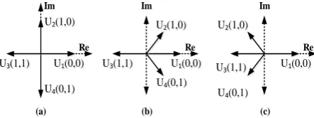
By taking all the possible cases of Sb and Sc into account, the phase-to-neutral voltage values are provided in Table 1. If the upper and lower capacitor values are enough to maintain the capacitor voltage constant in Udc/2, 4
voltage vectors with 4 possible combinations are produced (Figure 2a). The states of vectors in Figures 2(b) and 2(c) are shown in Udc1<Udc2 and Udc1>Udc2
modes. The position of the vectors is calculated and illustrated in Figure 2.
3. MPFC for LIM DRIVE with 4-SWITCH INVERTER
In the proposed method, the flux and force controllers are PFC. Based on the standard PFC method, a 2-mode algorithm is done: prediction of flux and force, and optimization of the cost function [18- 21].
U3(1,1)
U4(0,1)
U1(0,0)
U2(1,0) Im
Re
(a)
U3(1,1)
U4(0,1)
U1(0,0)
U2(1,0) Im
Re
(b)
U3(1,1)
U4(0,1)
U1(0,0)
U2(1,0) Im
Re
(c)
Figure 2. Voltage vectors of the 4-switch inverter in the
case of: (a) Udc1=Udc2, (B) Udc1<Udc2, (C) Udc1>Udc2
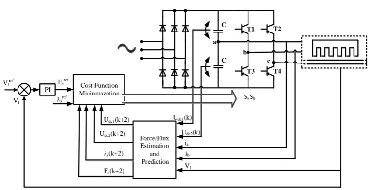
The structure of LIM drive fed by the B4 inverter using the PFC method is depicted in Figure 3.
3. 1. Prediction of the Flux and Force The accurate estimation of flux and force is necessary for the accurate performance of MPFC. In this paper, a Luenberger observer is adapted in the fast speed range for high precision. With introduction of the stator current error feedback, the precision of estimation and observer became more resistant against the change of motor parameters.
The LIM model are are state as follows:
qs ds qr dr qs ds sh r l r l sh r r ls r l ls s r l ls r ls s r qr dr qs ds u u Lls Lls i i M R R v p R v p M R R R ML R Lls v p L R R Lls v p ML R L R R i i dt d 0 0 0 0 1 0 0 1 2 0 2 0 2 0 2 0 (13 )
where, MLm
1f
Q
, RshRrf
Q .The mathematical model of the observer by using Equation (1) for LIM, is as follows:
is is
G Bu x A dt x
dˆ ˆ ˆ
(14)
where, xˆ
iˆs ˆs
Tare the variables of estimation. In the classic observer for the drives of LIMs, the poles of observer are designed proportional to the poles of the LIM [21], which creates a large imaginary part at high speeds. In order to solve this issue, movement of the real part of observer poles to the left in the complex design in comparison with the poles of LIM has been proposed, while the imaginary part of the observer poles does not change [22-24]. This method of movement is easy to implement and improves the convergence and stability of observer, especially at high speeds.The flux and current of stator at k+1and k+2 moments are calculated from the Equation (13) and its adjustment were calculated by Equation (14). With the current at k+1 and k+2 moments, the electromagnetic force of Equation (7) is calculated as follows:
( 2) ( 2) ( 2) ( 2)
TABLE 1. Switching functions and output voltages of B4 inverter
Output Voltage Switch On
States
UcN
UbN
UaN
Sc Sb
-Udc2/3 -Udc2/3
2 .Udc2/3 T4
T2 0
0
2(Udc2+Udc1)/3 -(2Udc2+Udc1)/3
(Udc2-Udc1)/3 T3
T2 1
0
(2Udc2+Udc1)/3 (2Udc2+Udc1)/3
(Udc2-Udc1)/3 T4
T1 0
1
Udc1/3 Udc1/3
2 .Udc1/3 T3
T1 1
1
PI
Force/Flux Estimation
and Prediction Cost Function
Mininmazation Feref
Fe(k+2)
ia
λs(k+2) λs
ref
Vlref
Vl
C
b c
ib
Udc1(k)
Udc2(k)
Udc1(k+2)
Udc2(k+2)
a
Sa Sb C
T1 T2
T3 T4
Vl
Figure 3. Structure of the B4 inverter-fed linear induction motor with the PFC method.
3. 2. The Cost Function As mentioned before, the stator flux and force is predicted as primary states using the predictive model with the is(k) and λs(k) variables at the moment of k+1 [25]. The aim is to make the stator flux and force follow their references. In other words, the error between the estimated flux and force, and their reference values should be minimized. This yields a cost function as follows:
1,2,3,4
1 ˆ 1
ˆ
j
k k
k F F
g s j
ref s j e ref e
j
(16)
We knew that there is a single-stage delay in the digital implementation. In other words, the chosen voltage vector at moment k would not be applied at moment k+1 [25-28]. In order to remove this delay, in Equation (16) the amount at k+2 moment is assumed to be proportional to k+1 moment; therefore, the cost function is rewritten as follows:
1,2,3,4
2 ˆ 2
ˆ
j
k k
k F F
g s j
ref s j e ref e
j
(17)
3. 3. Reduction of Voltage DC-Link offset The improper angle of the current of phase “a” or imbalance of the current in two capacitors results in deviation of the voltage [10]. According to Figure 2, the offset of capacitor voltage is related to the gain increase of the inverter and the reliable performance of 4-switch inverter. Hence, it is necessary to remove the offset of capacitor voltages. Consider the U4(1,0) switching mode
shown in Figure 4. Two current loops are created. Then, idc1 and idc2 are calculated. By the same method, the
DC-link current of the other three vectors is calculated. The currents of the DC-link is expressed as follows:
b
c
c
b dc
c c b b dc
S i S i i
S i S i i
1 . 1
. . .
2 1
(18)
In the above equations, idc1 and idc2 are the currents of
the upper and lower DC-links respectively, and ib and ic
C
b
c a
C
Udc1
Udc2 idc1
idc2
ia ib
ic U4(0,1)
Figure 4. Current paths in the switching mode U4
t t
dc dc
dc
t t
dc dc
dc
dt i C U U
dt i C U U
0 0
2 2
2
1 1
1
/ 1 ˆ
/ 1 ˆ
(19)
where, C is the capacity of DC-link capacitors.
By employing the Euler formula for discretization (18), the capacitor currents at the k sampling time are calculated as follows:
b
b
c c
dcc c b b dc
S k i S k i k i
S k i S k i k i
1 . 1
.
. .
2 1
(20)
Moreover, using the Euler formula for discretization (19), Vˆdc1
k1
and Vˆdc2
k1 at the k+1 time are calculated as follows:
dc
dc
s dcs dc dc
dc
T k i C k U k U
T k i C k U k U
. . / 1 ˆ
1 ˆ
. . / 1 ˆ
1 ˆ
2 2
2
1 1
1
(21)
1 ˆ1k
Udc and Uˆdc2
k1
are calculated using a similar method.In order to reduce the capacitor voltage offset, the cost function is calculated by adding the third term to the cost function of Equation (17) as follows:
1,2,3,4
2ˆ 2 ˆ
2 ˆ 2
ˆ
2 1
j U
k U k U k
k k
k F F g
dc
j dc j dc U
j s ref s j e ref e j
dc
(22)
where Udc is the DC-link voltage which can be calculated by Udc=Udc1+Udc2 and kUdc is the weight coefficient of the DC-link capacitor voltage offset reduction.
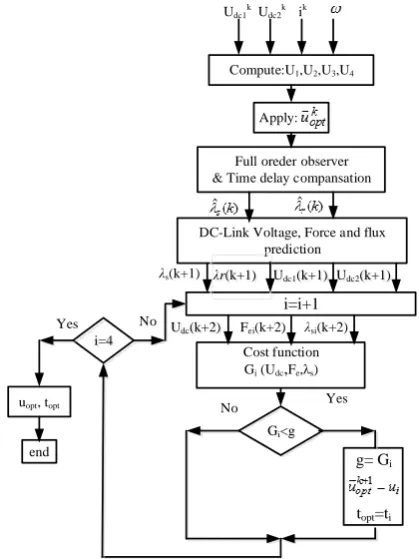
The proposed method can be implemented as shown is Figure 5. The k, k+1, and k+2 subscripts show the value of variables at k, k+1, and k+2 sampling times
respectively. uoptk
and uoptk1
are the optimal voltage vectors at current repetition loops.
Apply:
DC-Link Voltage, Force and flux prediction
Cost function Gi (Udc,Fe,λs)
Gi<g
g= Gi
topt=ti
λs(k+1)
λsi(k+2)
Fei(k+2)
Yes No
No
Full oreder observer & Time delay compansation
Compute:U1,U2,U3,U4
i=i+1
i=4
uopt, topt
end
Yes Udc(k+2)
Udc1(k+1)
Udc1 kU
dc2 k ik
λr(k+1) Udc2(k+1)
Figure 5. Flowchart of proposed PFC scheme
As mentioned before, a high degree of flexibility is optained by the proposed control method due to its online optimization algorithm, The uncertainties and limitations of the system (i.e. the capacitor voltage offset) could be considered in the cost function.
4. ANALLYSIS AND DISCUSSION OF THE WEIGHT COEFFICIENT
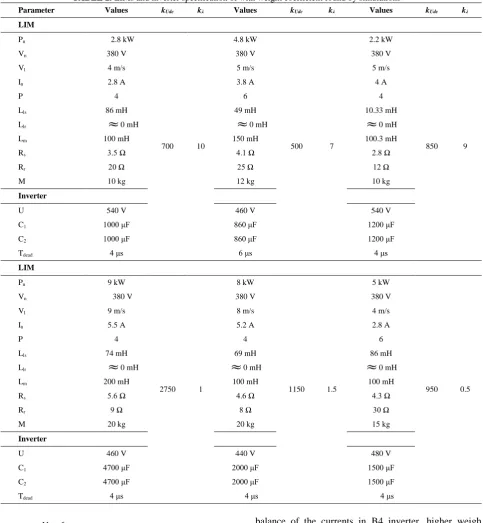
According to Equation (22), it is clear that only the weight coefficients are adjustabls in the cost function in the proposed method. Therefore, it is essential to analyze and discuss the effects of such parameters. However, no method has been introduced for calculation of the values of these parameters. Thereupon, such values are calculated by the simulation. In order to analyze the effects of weight coefficients, simulations have been performed for several different LIMs in MATLAB software and is presented in Table 2. According to this table, the weight coefficients of stator flux and the capacitor voltage offset reduction are calculated from the following relationships:
f T N
C U k
dead s
dc
Udc
TABLE 2. LIMs and inverter specification of with weight coefficient found by simulations
kλ
kUdc Values
kλ
kUdc Values
kλ
kUdc Values
Parameter
LIM
9 850 2.2 kW
7 500 4.8 kW
10 700 2.8 kW
Pn
380 V 380 V
380 V Vn
5 m/s 5 m/s
4 m/s Vl
4 A 3.8 A
2.8 A In
4 6
4 P
10.33 mH 49 mH
86 mH Lls
0 mH
0 mH
0 mH Llr100.3 mH 150 mH
100 mH Lm
2.8 Ω 4.1 Ω
3.5 Ω Rs
12 Ω 25 Ω
20 Ω Rr
10 kg 12 kg
10 kg M
Inverter
540 V 460 V
540 V U
1200 μF 860 μF
1000 μF C1
1200 μF 860 μF
1000 μF C2
4 μs 6 μs
4 μs Tdead
LIM
0.5 950 5 kW
1.5 1150 8 kW
1 2750 9 kW
Pn
380 V 380 V
380 V Vn
4 m/s 8 m/s
9 m/s Vl
2.8 A 5.2 A
5.5 A In
6 4
4 P
86 mH 69 mH
74 mH Lls
0 mH
0 mH
0 mH Llr100 mH 100 mH
200 mH Lm
4.3 Ω 4.6 Ω
5.6 Ω Rs
30 Ω 8 Ω
9 Ω Rr
15 kg 20 kg
20 kg M
Inverter
480 V 440 V
460 V U
1500 μF 2000 μF
4700 μF C1
1500 μF 2000 μF
4700 μF C2
4 μs 4 μs
4 μs Tdead
rated rated
s i T
f N k
(24)
4. 1. Weight Cofficient of the Stator Flux The parameters of the simulation and test system studied are provided in Table 3. kλ is the weight coefficient that increases or decreases the relative importance of force control compared to the flux control. If the importance of both is the same, this coefficient will be equal to 1. Since the currents directly control the stator flux, to establishe
balance of the currents in B4 inverter, higher weigh coefficient is expected. According to the Equation (24) and the values given in Table 3, the stator flux weight coefficient is obtained as follows:
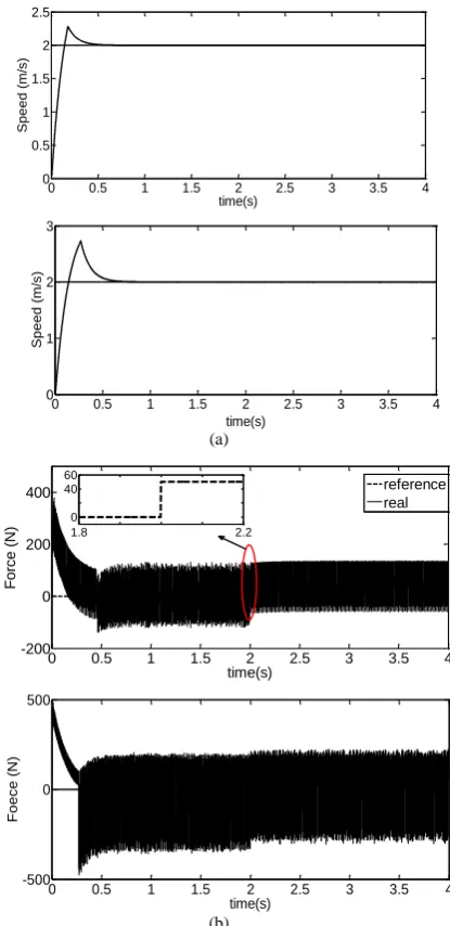
Figure 6 presents the simulation results using the conventional [20] and proposed methods at the constant speed of 2 m/s and load force of 50 N for the kλ =3 where
1001.45 100050 10 5 . 5 4
10 2040 540
6 6
f T N
C U k
dead s
the reference of the stator flux is considered to be 0.9 Wb. As observed in Figure 6, although the higher designation of weight coefficient of stator flux somewhat optimizes the balance of current, because the weight coefficient of the DC-link capacitor voltage offset reduction is ignored, the electromagnetic force has high ripple which causes a unbalance in the waveform of phase current.
4. 2. Weghit Cofficient of the Capacitor Voltage Offset Reduction The kUdc weight coefficient expresses the relative importance of the capacitor voltage offset compared to the control system. With a larger weight coefficient, the voltages of two capacitors converge faster. According to Equation (23) and using the values given in Table 3, the stator flux weight coefficient is obtained as follows:
3 976 . 2 8 . 4 14
50
4
rated rated
s i T
f N k
In order to analyze the effect of kUdcand to prove the value of the weight coefficient obtained by Equation (23), the results are investigated for two values of weight coefficient. The simulation results at the speed of 2 m/s with the nominal force of 50 N.m for kUdc=1000 and
kUdc=2000 are shown and analyzed in Figure 7(a), (b), (c), (d). In these figures, behavior of the speed, the electromagnetic force, stator flux, and phase current during of the voltage offset reduction are illustrated. Comparison between Figures 7 for kUdc=1000 and
kUdc=2000 and Figure 6 shows that using the weight coefficient and the voltage offset reduction, the force ripple decreases and the motor speed coincides more accurately.
TABLE 3. LIM and inverter pararmeters
Values Parameter
LIM
8.5 kW Rated power (Pn)
290 V Rated voltage (Vn)
5 m/s Rated speed (Vl)
4.8 A Rated current (In)
3 Pole pairs (P)
69 mH Primary leakage inductance (Lls)
200 mH Magnetizing resistance (Lm)
10.6 Ω Primary resistance (Rs)
30 Ω Secondary resistance (Rr)
20 kg Moving mass (M)
Inverter
460 V DC-link voltage (U)
860 μF DC-link capacitors (C1, C2)
(a)
(b)
Figure 6. (a) Speed (top): proposed method, (bottom):
conventional, (b) electromagnetic force (top): proposed method, (bottom): conventional, at constant speed of 2 m/s and load force of 50 N for the kλ =3
Moreover, based on comparison between Figure 7 for kUdc=1000 and kUdc=2000, with proper determination of the weighting coefficient according to Equations (23) and (24), ripple of the stator flux and electromagnetic force decreases. Therefore, a satisfactory performance at kUdc=1000 is achieved.
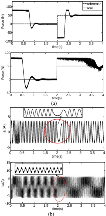
Simulation results for conventional [20] and proposed methods at the step speed of 2-4 m/s for kUdc=1000 are depicted in Figure 8. Due to the designation of a proper value for the weight coefficient of the capacitor voltage offset reduction in proposed method, the balance of the current improved the ripple of the stator flux, and the ripple of the electromagnetic force is acceptable.
0 0.5 1 1.5 2 2.5 3 3.5 4
0 0.5 1 1.5 2 2.5
time(s)
S
p
e
e
d
(
m
/s
)
0 0.5 1 1.5 2 2.5 3 3.5 4
0 1 2 3
time(s)
S
p
e
e
d
(
m
/s
)
0 0.5 1 1.5 2 2.5 3 3.5 4
-200 0 200 400
time(s)
F
o
rce
(
N) 1.8 2.2
0 40 60
reference real
0 0.5 1 1.5 2 2.5 3 3.5 4
-500 0 500
time(s)
F
o
e
c
e
(
N
(a)
(b)
(c)
(d)
Figure 7. (a) Speed, (b) force, (c) flux stator, (d) Current of
phase "a" at speed of 2 m/s and load force of 50 N for kUdc=2000 and kUdc=1000
(a)
(b)
Figure 8. (a) Electromagnetic force (top): proposed method,
(bottom): conventional, (b) Current a-phase (top): proposed method, (bottom): conventional, at speed reference as a step function from 2-4 m/s with load force of 50 N for kUdc=1000
5. CONCLUDING REMARKS
The SMPFC of a LIM with a three-phase 4-switch inverter is analyzed. In order to decrease the ripple of stator flux and electromagnetic force, tuning of weight
0 1 2 3 4
0 1 2 3
time(s)
S
p
e
e
d
(
m
/s
)
reference real kudc=2000
0 1 2 3 4
0 1 2 3
time(s)
S
p
e
e
d
(
m
/s
)
Reference real kudc=1000
0 1 2 3 4
-50 0 50 100
time(s)
F
o
rc
e
(N)
reference real kudc=2000
0 1 2 3 4
-50 0 50 100
time(s)
F
o
rc
e
(
N)
reference real kudc=1000
0 1 2 3 4
0.8 0.85 0.9 0.95 1
time(s)
S
ta
to
r F
lu
x
(
W
b
) kudc=2000
0 1 2 3 4
0.8 0.85 0.9 0.95 1
time(s)
F
lu
x
S
ta
to
r (
W
b
)
kudc=1000
0 1 2 3 4
-10 -5 0 5 10
time(s)
Ia
(A
)
kudc=2000
0 1 2 3 4
-10 -5 0 5 10
time(s)
Ia
(A
)
kudc=1000
0 0.5 1 1.5 2 2.5 3 3.5 4
-100 -50 0 50 100
time(s)
F
o
rce
(
N)
reference real
0 0.5 1 1.5 2 2.5 3 3.5 4
-50 0 50 100
time(s)
F
o
rc
e
(
N
)
0 0.5 1 1.5 2 2.5 3 3.5 4
-5 0 5
time(s)
Ia
(
A
)
0 0.5 1 1.5 2 2.5 3 3.5 4
-10 -5 0 5 10 15
time(s)
Ia
(A
coefficient of flux at PFC is employed. Next, to improve performance of the proposed method, a weight coefficient is defined for the capacitor voltage offset reduction, because the balance of currents is inappropriate. In order to analyze the effects of weight coefficients, simulations have been performed for several different LIMs in MATLAB software and the weight coefficients of stator flux and the capacitor voltage offset reduction are calculated from relationships. According to the results of numerical simulations, the balance of the currents is improved by determining the appropriate value for the weight coefficient of the capacitor voltage offset reduction. Furthermore, ripple of the stator flux and electromagnetic force more decreases by determining the appropriate value for the weight coefficient of the capacitor voltage offset reduction compared to the mode where the weight coefficient is only designated for the stator flux.
6. REFERENCES
1. Boldea, I. and Nasar, S.A., "Linear electric actuators and generators", IEEE International Conference in Electric
Machines and Drives Record, (1997), MA1/1.1-MA1/1.5.
2. Boldea, I., "Linear electric machines, drives, and maglevs handbook, CRC Press, (2013).
3. Q. F. Lu and W. H. Mei, "Recent development of linear machine topologies and applications," CES Transactions on Electrical
Machines and Systems, Vol. 2, No. 1, (2018), 65-72.
4. G. Lv, Z. Liu and S. Sun, "Analysis of Torques in Single-Side Linear Induction Motor With Transverse Asymmetry for Linear Metro," IEEE Transactions on Energy Conversion, Vol. 31, No. 1, (2016), 165-173.
5. D. Campos-Delgado, D. Espinoza-Trejo, and E. Palacios, “Fault-tolerant control in variable speed drives: A survey,” Electric
Power Application., IET, Vol. 2, No. 2, (2008), 121–134.
6. Francesco Alonge, Maurizio Cirrincione, Marcello Pucci, Antonino Sferlazza, "Input–output feedback linearizing control of linear induction motor taking into consideration the end-effects. Part I: Theoretical analysis", Control Engineering Practice, Vol 36, (2015), 133-141.
7. B. A. Welchko, T. A. Lipo, T. M. Jahns, and S. E. Schulz, “Fault tolerant three-phase AC motor drive topologies: A comparison of features, cost, and limitations,” IEEE Transactions on Power Electronics, Vol. 19, No. 4, (2004), 1108– 1116.
8. F. Blaabjerg, D. O. Neacsu, and J. K. Pedersen, “Adaptive SVM to compensate DC-Link voltage ripple for four-switch three-phase voltage-source inverters,” IEEE Transactions on Power Electronics, Vol. 14, No. 4, (1999), 743–752,
9. D. M. Lee, J. B. Park, and H. A. Toliyat, “A simple current ripple reduction method for B4 inverters,” Journal of Electrical
Engineering Technology, Vol. 8, No. 5, (2013), 1062– 1069
10. R. Wang, J. Zhao, and Y. Liu, “A comprehensive investigation of four-switch three-phase voltage source inverter based on double Fourier integral analysis,” IEEE Transactions on Power
Electronics, Vol. 26, No. 10, (2011), 2774–2787
11. M. N. Uddin, T. S. Radwan, and M. A. Rahman, “Fuzzy-logic controller- based cost-effective four-switch three-phase inverter-fed IPM synchronous motor drive system,” IEEE Transactions
on Industrial Application, Vol. 42, No. 1, (2006), 21–30,
12. B. El Badsi, B. Bouzidi, and A. Masmoudi, “DTC scheme for a four-switch inverter-fed induction motor emulating the six-switch inverter operation,” IEEE Transactions on Power Electronics, Vol. 28, No. 7, (2013), 3528–3538
13. M. H. Holakooie, M. B. Bannae Sharifian, M.R. Feyzi. "Sensorless indirect field oriented control of single sided linear induction motor with a novel sliding mode MRAS speed estimator," International Journal of Engineering (IJE)
Transactions A: Basics, Vol. 28, No. 7, (2015), 1011-1020.
14. Mohammad Hosein Holakooie, Mansour Ojaghi, Asghar Taheri, "Full-order Luenberger observer based on fuzzy-logic control for sensorless field-oriented control of a single-sided linear induction motor", ISA Transactions, Vol. 60, (2016), 96-108.
15. J. H. Lee, “Model predictive control: Review of the three decades of development,” International Journal of Control, Automation
and Systems, Vol. 9, No. 3, (2011), 415–424.
16. Wenxiang Song, Shengkang Le, Xiaoxin Wu, and Yi Ruan, “An Improved Model Predictive Direct Torque Control for Induction Machine Drives,” Journal of Power Electronics, Vol. 17, No. 3, (2017), 674-685.
17. Yasser Shoukry, M. Watheq El-Kharashi, Sherif Hammad, “An embedded implementation of the generalized predictive control algorithm applied to automotive active suspension system,”
Computers & Electrical Engineering, Vol. 39, No. 2, (2013), 512–529.
18. Fengxiang Wang,Xuezhu Mei,Jose Rodriguez, “Model Predictive Control of Electrical Drive systems- on overview,” CES
Transactions on Electrical Machines and Systems, Vol. 1, No.
3, (2017), 219-230.
19. S. Kouro, P. Cort´es, R. Vargas, U. Ammann, and J. Rodr´ıguez, “Model predictive control—A simple and powerful method to control power converters,” IEEE Transactions on Power Electronics, Vol. 56, No. 6, (2009), 1826–1838.
20. C. A. Rojas, J. Rodriguez, F. Villarroel, J. R. Espinoza, C. A. Silva, and M. Trincado, “Predictive torque and flux control without weighting factors,” IEEE Transactions on Power Electronics, Vol. 60, No. 2, (2013), 681–690.
21. G. Kang and K. Nam, “Field-oriented control scheme for linear induction motor with the end effect,” IEE Proceedings-Electric
Power Applications, Vol. 152, No. 6, (, 2005), 1565–1572.
22. Y. Cho, Y. Bak and K. B. Lee, "Torque-Ripple Reduction and Fast Torque Response Strategy for Predictive Torque Control of Induction Motors," IEEE Transavtions on Power Electronics, Vol. 33, No. 3, (2018), 2458-2470.
23. J. Rodriguez, R. M. Kennel, J. R. Espinoza, M. Trincado, C. A. Silva, and C. A. Rojas, “High-performance control strategies for electrical drives: An experimental assessment,” IEEE
Transactions on Industrial Electronics, Vol. 59, No. 2, (2012),
812–820.
24. T. Geyer, “Computationally efficient model predictive direct torque control,” IEEE Transactions on Power Electronics, Vol. 26, No. 10, (2011), 2804–2816.
25. S. A. Davari, D. A. Khaburi, and R. Kennel, “An improved FCS– MPC algorithm for an induction motor with an imposed optimized weighting factor,” IEEE Transactions on Power Electronics, Vol. 27, No. 3, (2012), 1540–1551.
26. Gayathri, M.N., Himavathi, S. and Sankaran, R., "Comparison of mras based rotor resistance estimator using reactive power and flux based techniques for space vector pwm inverter fed induction motor drives", International Journal of
Engineering-Transaction C: Aspects, Vol. 25, No. 3, (2012), 205-212.
models,” IEEE Transactions on Industrial Electronics, Vol. 56, No. 6, (2009), 1916 –1924.
28. Fateh, M. and Sadeghijaleh, M., "Voltage control strategy for
direct-drive robots driven by permanent magnet synchronous motors", International Journal of Engineering-Transactions B:
Applications, Vol. 28, No. 5, (2014), 709-716.
Sensorless Model Predictive Force Control with a Novel Weight Coefficients for
3-Phase 4-Switch Inverter Fed Linear Induction Motor Drives
S. Masomi Kazraji, M. R. Feyzi, M. B. B. Sharifian, S. Tohidi
Faculty of Electrical and Computer Engineering University of Tabriz, Tabriz, Iran
P A P E R I N F O
Paper history:
Received 27 December 2017 Received in revised form 14 April 2018 Accepted 26 April 2018
Keywords: Linear Induction Motor
Sensorless Model Predictive Force Control 4-switch Inverter
Weight Coefficient
هدیکچ
شیپ رگسح نودب لرتنک ( لدم رب ینتبم ورین نیب
SMPFC
اب یطخ ییاقلا روتوم یاهویارد لرتنک یارب یدنمتردق یشور )
زاف هس رترونیا 4
( 6 یم هچیئوس ) رترونیا عون نیا .دشاب
یم لاصتا /زاب رادم لکشم لح روظنم هب اطخ لمحت لرتنک یارب دناوت
یاهرترونیا رد هاتوک 6
هچیئوس (
B6
هب ) یارب شور کی هلاقم نیا .دوش هتفرگ راک
SMPFC
( یطخ ییاقلا روتوم
LIM
)
رترونیا کی طسوت هدش هیذغت 4
هب هچیئوس کنیل نزاخ ژاتلو تسفآ شهاک هارمه
DC
یم داهنشیپ هیبش .دهد یور یزاس
مرن رد فلتخم یطخ ییاقلا روتوم نیدنچ رازفا
MATLAB
ب ژاتلو تسفآ شهاک و روتاتسا راش ینزو بیارض نییعت یار
بیارض نییعت یارب هطبار کی ،سپس .تسا هدش ماجنا نزاخ
DC
هنیزه عبات رد
SMPFC
زا هدافتسا اب .تسا هدش داهنشیپ
رترونیا ژاتلو یاهرادرب ،هنیزه عبات رد ینزو بیارض طباور 4
شیپ یارب هچیئوس هب قیقد ینیب
.تسا هدمآ تسد نیب لداعت
نایرج یم دوبهب نزاخ ژاتلو تسفآ شهاک ینزو بیرض یارب بسانم رادقم نییعت اب اه هیبش جیاتن .دیای
شور دییأت یارب یزاس
.تسا هدش هئارا یداهنشیپ یلرتنک
doi: 10.5829/ije.2018.31.09c.09