Please cite this article as: F. Azari Nasrabad, H. Hassanpour, S. Asadi Amiri, Adaptive Image Dehazing via Improving Dark Channel Prior, International Journal of Engineering (IJE), IJE TRANSACTIONS B: Applications Vol. 32, No. 2, (February 2019) 249-255
International Journal of Engineering
J o u r n a l H o m e p a g e : w w w . i j e . i rAdaptive Image Dehazing via Improving Dark Channel Prior
F. Azari Nasrabada, H. Hassanpoura, S. Asadi Amiri*b
a Faculty of Computer Engineering and IT, Shahrood University of Technology, Shahrood, Iran b Department of Technology and Engineering, University of Mazandaran, Babolsar, Iran
P A P E R I N F O
Paper history: Received 27 October 2018
Received in revised form 27 November 2018 Accepted 03 January 2019
Keywords:
Dehazing Image Enhancement Dark Channel Prior Segmentation
A B S T R A C T
The dark channel prior (DCP) technique is an effective method to enhance hazy images. Dark channel is an image with the same size as the hazy image which represents the haze severity in different places of the image. The DCP method suffers from two problems: it is incapable for removing haze from smooth regions, causing blocking effects on these areas; it cannot properly reduce a haze with a non-monotonic behavior. In this paper, an adaptive image dehazing method is proposed based on the DCP method to solve the problem of this method. In this method, to overcome the dark channel deficiency of the blocking effects, the dark channel is initially extracted. The hazy image is subsequently segmented into smooth and non-smooth regions. Regarding the smooth regions, the pixel values in the dark channel are reduced by dividing them with a rather great number. To solve the second problem, depending upon the haze severity, the haze removing technique is applied repeatedly until all the regions of the image are enhanced. Finally, the Gamma correction approach is used for contrast enhancement of the smooth regions. The performed subjective and objective comparison attest the superiority of the proposed method to the DCP one in removing the haze.
doi: 10.5829/ije.2019.32.02b.10
1. INTRODUCTION1
The outdoor images are degraded by the suspended particles in the atmosphere. Atmospheric absorption such as haze, fog, and smoke reduces the visibility of the scene and color shift may occur. Hence haze should be removed for extracting desirable information and features from the images.
There are two general methods for removing haze: multiple-image and single-image methods. The former uses multiple images or additional information. In polarization-filtered methods, images taken at different orientations are used to remove haze [1-3]. Some multiple-image based methods use images of the same scene at different weather conditions for removing haze [4-6]. Depth-based methods require the depth information from the user interactions to restore images [7, 8]. The shortcomings of the multiple-image methods are their additional need for information from multiple images and their preparation difficulty.
Single-image methods use a single image without the need for any additional information about the image. Tan
*Corresponding Author Email: [email protected] (S. Asadi Amiri)
[9] removed the haze by maximizing the local contrast in the restored image. However, this method is not effective in restoring natural colors in haze-free area of the image. Haze can also be removed using the transmission coefficient which are estimated by reflection of the suspended particles in the scene [10-12]. These methods are not suitable for a dense haze and require enough color information from the image.
He et al. proposed a dehazing algorithm based on DCP [13]. This method is based upon the assumption that at least one color channel has very low intensities within a window in a haze-free image. Hence, a haze-free image can be restored by estimating the transmission coefficient and the airlight. The light coming from the illuminant (e.g. sun) and scattered by the atmospheric particles towards the camera is the airlight. The light emanating from the object is attenuated by scattering, leading to the transmission coefficient.
method. This method may not preserve the edges. Ranota et al. [19] proposed a technique to fortify the DCP method in enhancing hazy images. This technique employs separate approaches for enhancing the smooth and non-smooth areas of a hazy image. It uses Gamma correction in the smooth regions and the DCP method in the non-smooth regions.
Although the existing DCP-based methods have good performance for removing haze, they may cause blurring effect and color distortion [16-21]. The DCP method has the same theory for removing haze from all parts of the image. Hence, it may cause blocking effect in the smooth regions and also cannot remove the haze from images with various severity of haze.
In this research, the hazy image is segmented into smooth and non-smooth regions. Then the effect of smooth regions is reduced in DCP method to overcome the blocking effect in these areas. Depending on the severity of haze in the non-smooth regions, the DCP method might be applied repeatedly until all regions be enhanced. Finally, a simple Gamma correction approach is used to improve the contrast of the smooth areas [22]. This paper is organized as follows. In section 2, the DCP approach for haze removal is introduced. The proposed method is presented in details in section 3. In section 4, the experimental results are provided with both the subjective and objective evaluations. Finally, the conclusion is driven in section 5.
2. THE DCP METHOD
A hazy image can be modeled as follows [13]:
𝐼(𝑥) = 𝐽(𝑥)𝑡(𝑥) + 𝐴(1 − 𝑡(𝑥)) (1)
where 𝐼, 𝐽, 𝑡, 𝐴, and 𝑥 are the hazy image, the haze-free image, the transmission coefficient, the global airlight, and the image pixel, respectively.
In Equation (1) the global airlight and the transmission coefficient are two unknown parameters. The DCP method is one of good methods for estimating these two parameters. The basis of DCP method is that hazy image is divided into overlapping windows (usually 15x15) and in each of these windows, one pixel is considered as the dark pixel. Then this dark pixel is replaced on all pixels in that window. To obtain the dark pixel, the minimums in the R, G, and B channels of the window are calculated. Then, the minimum of them is considered as the dark pixel [17].
Equation (2) is obtained by applying the DCP method on Equation (1).
𝑚𝑖𝑛𝑐(𝑚𝑖𝑛𝑦∈Ω(𝑥)( 𝐼𝑐(𝑦)
𝐴𝑐 )) = 𝑡̃(𝑥) 𝑚𝑖𝑛𝑐(𝑚𝑖𝑛𝑦∈Ω(𝑥)(
𝐽𝑐(𝑦)
𝐴𝑐 )) + (1 −
𝑡̃(𝑥)) (2)
In the above equation, 𝑐 is one of the color channels,
Ω(𝑥) represents the neighbors of pixel 𝑥,
𝑚𝑖𝑛𝑐(𝑚𝑖𝑛𝑦∈Ω(𝑥)( 𝐼𝑐(𝑦)
𝐴𝑐 )) is the normalized dark channel of the hazy image and 𝑡̃(𝑥) is the transmission coefficient for each patch.
Hazy regions in dark channel are brighter. Hence dark channel of haze-free image tends to zero. By replacing zero on dark channel of haze-free image in Equation (2), transmission coefficient can be obtained as bellow:
𝑡̃(𝑥) = 1 − 𝑤. 𝑚𝑖𝑛𝑐(𝑚𝑖𝑛𝑦∈Ω(𝑥)( 𝐼𝑐(𝑦)
𝐴𝑐 )) (3)
The airlight has a color similar to those of the bright regions. Hence for estimating the global airlight, the top 0.1% brightest pixels of the dark channel are selected. According to these pixels the highest intensity of the hazy image, is taken as the airlight [13].
The transmission coefficient image has some discontinuities. For refining and eliminating these discontinuities, the Laplacian method can be used which has been described in literature [19]. Finally, the haze-free image can be obtained from Equation (1) expressed below:
𝐽(𝑥) = 𝐼(𝑥)−𝐴
𝑚𝑎𝑥 (𝑡(𝑥),𝑡0)+ 𝐴 (4)
As 𝑡(𝑥) tends to zero in images with less haze, a minimum value for the transmission coefficient is considered (𝑡0= 0.1) [13].
3. THE PROPOSED ALGORITHM
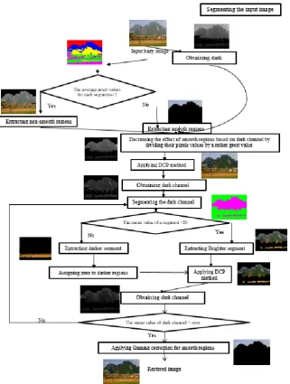
A block diagram of the proposed method can be seen in Figure 1. The DCP method is one of effective methods for removing haze. Despite the capability of DCP method, it has two important shortcomings which are resolved in this paper. The DCP method causes blocking effects on the smooth regions. To overcome this effect, the dark channel of the hazy image is extracted. Then the hazy image is segmented into the smooth and non-smooth regions. Based on the dark channel, the pixels values for smooth regions are reduced by dividing them with a rather great number.
The other problem with the DCP method is with non-monotonic behavior of the haze distortion on the images. Hence, the DCP method must be applied on some regions more than once. For this purpose, we use the dark channel information to check the need for re-applying the method.
The brighter areas in the dark channel imply that this method should be applied more than once on these regions.
Figure 1. Block diagram of the proposed haze removing method
Finally Gamma correction method [22] is used to enhance the smooth regions of the hazy image. These steps are explained in detail in the following subsections.
3. 1. Smooth and Non-Smooth Region
Segmentation For separating the smooth and
non-smooth regions, first the pixonal approach, described in litersture [17], is utilized to segment the hazy image. This approach is used because of the better cohesion of the segments is created.
After formation of the pixons, the final segmentation takes place. For this purpose, the Fuzzy C-Mean (FCM) algorithm which is one of the most widely used clustering algorithms, is employed [23]. In this paper the FCM is
utilized to divide the pixonal image into five segments, and this segmentation was tested on all images of the data base [24]. One sample of pixonal segmentation is showed in Figure 2(b).
To separate the smooth and non-smooth regions from the previous segmentation, the texture information can be used. A texture image, which is of the same size as the hazy image (I) can be obtained as follows [25]:
𝐼̅(𝑖, 𝑗) = 2
(2𝐿+1)2∑ ∑ 𝐼(𝑖 + 𝑘, 𝑗 + 𝑙)
𝐿 𝑙=−𝐿 𝐿
𝑘=−𝐿 (5)
𝑀𝑇= |𝐼(𝑖, 𝑗) − 𝐼̅(𝑖, 𝑗)| (6)
where 𝐼̅ is the local average and 𝑀𝑇 is the local variance
Figure 2(c) shows the texture image of the hazy image. As it can be seen, the dense texture regions have larger variance.
According to the texture image, the average pixel values for each of the five segments achieved in the previous step is calculated. Then the smooth regions can be separated by considering a threshold value (the threshold value of 2 is considered in this experimentally research work).
3. 2. Removing Haze From Image As mentioned
earlier, the DCP method causes the blocking effect on the smooth regions. To overcome this shortcoming, the effect of the smooth regions must be reduced in the DCP method. For this purpose, the dark channel of the hazy image is initially extracted. Then the effect of the smooth regions, identified in the previous section, are decreased by dividing their pixels values with a rather great value (we chose the value to be 7 in this paper). This reduction is illustrated in Figure 2(d). Then the DCP method is applied to the whole image once (Figure 2(e)).
Another problem of the DCP method is that, it is not suitable for images with various severity of haze. Hence, once the results are not satisfactory, DCP should be applied repeatedly. For removing the haze from images with various severity of haze, the dark channel of the hazy image is segmented into brighter and darker segments using pixon-based approach. For formation of pixons, the value of a pixel is compared with its neighboring pixels. If this value is less than a threshold, they are considered as one pixon. We considered the threshold value as 20 in this experimental work.
The bright regions in the dark channel means that the haze was not removed from these regions properly. Hence, the haze-free regions are assigned to zero and the DCP method is applied on the hazy regions. This algorithm is repeatedly applied to the hazy regions until the average value for the dark channel becomes lower
than a predefined threshold value. The threshold value of zero is set in this experimental work.
By all the steps taken above, there might still be distortion in the image which is due to the Gamma distortion. Hence we need to use Gamma correction approach to enhance the image [26]. Finally, the Gamma correction is used to enhance the smooth regions. The Gamma correction approach is described as follows [17]:
𝐸(𝑥, 𝑦) = 𝑇(𝑥, 𝑦)𝛾 (7)
when the 𝛾 value is less than one, the enhanced image becomes lighter than the input image; and when the 𝛾
value is greater than one, the enhanced image becomes darker than the input image [21, 27]. The Gamma value of 1.5 is considered in this experimental work to enhance the smooth regions of the hazy image. An example of the above-mentioned process can be seen in Figure 2.
4. EXPERIMENTAL RESULTS
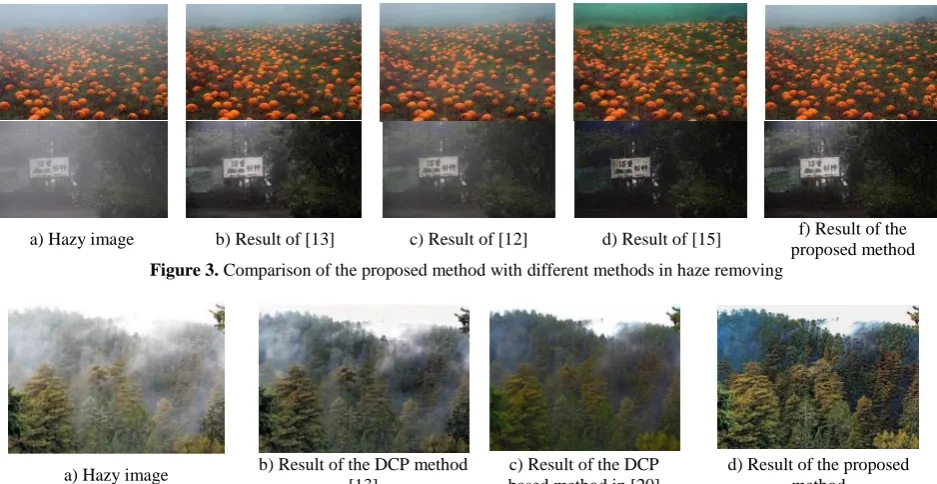
In this paper a technique for improving the DCP method in enhancing hazy images is introduced. The proposed method was evaluated on various images and its performance was compared with the performance of a number of well-known methods [12, 13, 15, 17, 20]. There are additional literature [13, 17, 20] have focussed on some of the DCP-based methods. Results of some recent methods are compared with the proposed method in Figures 3.
Results presented by Galdran [12] and He et al.[13] have some limitations in removing dense haze. The results presented by Li and Zheng [15] are not effective in removing haze from sharp regions. But, the proposed method can restore natural color with no need to further color information from the image, and is good for removing dense haze as well as sharp regions.
f) Final result e) Overcoming the
blocking effect of smooth regions in
DCP method d) Reduced the
effect of smooth regions in dark
channel c) Texture image
b) Pixonal image a) Hazy image
Figure 2. Outputs of the proposed method at different stages
Subjective comparison results of the DCP-based image dehazing methods with the proposed method are shown in Figures 4-5. As it can be seen the proposed method provides more favorable results in removing the haze from regions with different severity of haze.
It is noteworthy that, since most of the existing methods do not provide the results on specified
databases, we compared the proposed method with the state-of-the-art on the images reported in their papers.
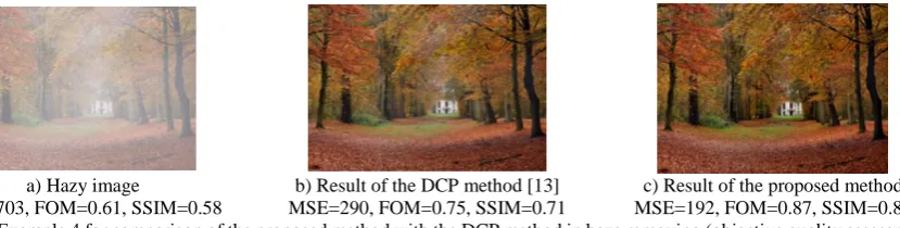
available, we used some haze-free images. First, these images were damaged by different amount of the haze, and then the proposed method was applied to them. Figures 6-7 illustrate two instance results of the proposed method in comparison of objective quality assessment
values with the method in [13]. As can be seen, the proposed method produces better objective values than the method reported in literature [13]. These values are also in good agreement with the subjective evaluations of the human observers.
a) Hazy image b) Result of [13] c) Result of [12] d) Result of [15] f) Result of the proposed method
Figure 3. Comparison of the proposed method with different methods in haze removing
a) Hazy image b) Result of the DCP method [13]
c) Result of the DCP based method in [20]
d) Result of the proposed method
Figure 4. Example 1 for comparison of the proposed method with the DCP base methods in haze removing (subjective quality
assessment)
a) Hazy image b) Result of the DCP method [13]
c) Result of the DCP
base method in [17] d) Result of the proposed method
Figure 5. Example 2 for comparison of the proposed method with the DCP base methods in haze removing (subjective quality
assessment)
c) Result of the proposed method MSE=190, FOM=0.9, SSIM=0.89 b) Result of the DCP method [13]
MSE=361, FOM=0.78, SSIM=0.73 a) Hazy image
MSE=692, FOM=0.61, SSIM=0.54
a) Hazy image
MSE=703, FOM=0.61, SSIM=0.58
b) Result of the DCP method [13] MSE=290, FOM=0.75, SSIM=0.71
c) Result of the proposed method MSE=192, FOM=0.87, SSIM=0.89
Figure 7. Example 4 for comparison of the proposed method with the DCP method in haze removing (objective quality assessment)
5. CONCLUSIONS
In this paper, an improved image dehazing algorithm was proposed using the dark channel prior. DCP method causes the blocking effect on the smooth regions and it is not suitable for images with a different severity of haze. The proposed method has resolved these two shortcomings of the DCP method. To overcome the problem of blocking effect, the image is segmented into the smooth and non-smooth regions. Then the blocking effects on the smooth regions is reduced. For the second problem, the method is applied repeatedly to properly remove the haze. The quantitative and qualitative comparison results provided in this paper showed that the proposed technique is superior to the DCP method and other existing DCP-based methods in enhancing hazy image.
6. REFERENCES
1. Gao, Y., Hu, HM., Wang, S. and Li, B., “A fast image dehazing algorithm based on negative correction”, Elsevier Signal
Processing, Vol. 2, (2014), 380-398.
2. Schechner, Y. Y., Narasimhan, S. G. and Nayar, S. K., “Instant dehazing of images using polarization”, IEEE Computer Vision
and Pattern Recognition, Vol. 1, (2001), 325-332.
3. Shwartz, S., Namer, E. and Schechner, Y. Y., “Blind haze separation”, IEEE Computer Vision and Pattern Recognition, Vol. 2, (2006), 1984-1991.
4. Narasimhan, S. G. and Nayar, S. K., “Chromatic framework for vision in bad weather”, IEEE Computer Vision and Pattern
Recognition, Vol. 1, (2000), 598-605.
5. Nayar, S.K. and Narasimhan, S.G., “vision in bad weather”,
IEEE Computer Vision, Vol. 2, (1999), 820-827.
6. Narasimhan, S. G. and Nayar, S. K., “Contrast Restoration of Weather Degraded Images”, IEEE Pattern Analysis and
Machine Intelligence, Vol. 25, (2003), 713-724.
7. Kopf, J., Neubert, B., Chen, B. Cohen, M., Cohen, D., Deussen, O., Uyttendaele, M. and Lischinski, D., “Deep photo: model-based photograph enhancement and viewing”, Association for
Computing Machinery, Vol.27, (2008), 116.
8. Narasimhan, S. G. and Nayar, S. K. “Interactive deweathering of an image using physical models”, IEEE Workshop Color and
Photometric Methods in Computer Vision, Vol.6, (2003), 1.
9. Tan, R., “Visibility in bad weather from a single image”, IEEE
Computer Vision and Pattern Recognition, Vol. 25, (2008), 1-8.
10. Fattal, R., “Single image dehazing”, Analysis and Machine Intelligence, Vol.27, (2008), 72.
11. Fan, X. and Luo, z., “Haze editing with natural transmission”, The
Visual Computer, Vol. 32, (2016), 137-147.
12. Galdran, A. “Image dehazing by artificial multiple-exposure image fusion”, Signal Processing, Vol. 149, (2018), 135-147. 13. He, K., Sun, J. and Tang, X., “Single image haze removal using
dark channel prior”, IEEE Computer Vision and Pattern
Recognition, Vol. 33, (2011), 2341-2353.
14. He, K., Sun, J. and Tang, X., “Guided Image Filtering”, Pattern
Analysis, Vol.35, (2013), 1397–1409.
15. Li, Z. and Zheng, J., “Single image de-hazing using globally guided image filtering”, IEEE Transactions on Image
Processing, Vol. 27, (2018), 442-450.
16. Tarel, J. and Hautiere, N., “Fast visibility restoration from a single color or gray level image”, Computer Vision, Vol.16, (2009), 2201-2208.
17. Hassanpour, H., Azari, F. and Asadi, S., “Improving Dark Channel Prior for Single Image Dehazing”, International
Journal of Engineering, Transactions C: Aspects, Vol. 28, No.
6, (2015), 880-887.
18. Bai, L. and Wu, Y., “Real time image haze removal on multi-core DSP”, Procedia Engineering, Vol. 99, (2015), 244-252. 19. Ranota, H. and Kaur, P., “A new single image dehazing approach
using modified dark channel prior”, Advances in Intelligent
Informatics, Vol. 98, (2015), 77-85.
20. Zeng, Y. and Liu, X., “A multi-scale fusion-based dark channel prior dehazing algorithm”, International Conference on Graphic
and Image Processing, Vol. 6, (2014), 94-98.
21. Hung, C., Lin, Y. and Wang, H., “Image haze removal of optimized contrast enhancement based on GPU”, Springer
Singapore, Vol. 3, (2016), 53-63.
22. Asadi, S. and Hassanpour, H., “A preprocessing approach for image analysis using gamma correction”, International Journal
of Computer Applications, Vol. 38, (2012), 38-46.
23. Hassanpour, H., Yousefian, H. and Zehtabian, A., “Pixon-based image segmentation in Image Segmentation”, Intech pen Access
Publisher, Vol. 2, (2011), 495-515.
24. Fattal, R., and Raanan, A., “Dehazing using Color-Lines”,
http://www.cs.huji.ac.il/~raananf/projects/dehaze_cl/results.
Accessed 12 August 2016.
25. Carvalho, F., “Fuzzy c-means clustering methods for symbolic interval data”, Pattern Recognition Letters, Vol. 28, (2007), 423-437.
26. Ma, K., Duanmu, Z., Wu, Q., Wang, Z., Yong, H., Li, H. and Zhang, L., “Waterloo exploration database: New challenges for image quality assessment models”, IEEE Transactions on Image
Processing, Vol. 26, (2017), 1004-1016.
27. Hassanpour, H. and Asadi, S., “Image quality enhancement using pixel wise gamma correction”, International Journal of
Engineering, Transactions B: Applications, Vol. 24, No. 4,
Adaptive Image Dehazing via Improving Dark Channel Prior
F. Azari Nasrabada, H. Hassanpoura, S. Asadi Amirib
a Faculty of Computer Engineering and IT, Shahrood University of Technology, Shahrood, Iran b Department of Technology and Engineering, University of Mazandaran, Babolsar, Iran
P A P E R I N F O
Paper history: Received 27 October 2018
Received in revised form 27 November 2018 Accepted 03 January2019
Keywords:
Dehazing Image Enhancement Dark Channel Prior Segmentation
هدیکچ
هزادنا مه یریوصت ،کیرات لاناک .تسا هم یاراد ریواصت تیفیک ندرب لااب یارب رثوم شور کی کیرات لاناک شور ریوصت اب
تمسق رد ار هم نازیم هک تسا دولآ هم یم ناشن ریوصت فلتخم یاه
هب رداق :تسا لکشم ود یاراد کیرات لاناک شور .دهد
یم یحاون نیا رد یکولب رثا داجیا بجوم و تسین راومه یحاون زا هم فذح یاراد ریواصت یارب شور نیا نینچمه .دوش
لاقم نیا رد .تسین بسانم نگمهان هم شور نیا رد .تسا هدش داهنشیپ کیرات لاناک شور ساسا رب هم فذح شور کی ه
یم جارختسا کیرات لاناک ریوصت ادتبا ،راومه یحاون رد یکولب رثا لکشم رب هبلغ یارب تمسق هب ریوصت نیا سپس .دوش
یاه
یم میسقت راومه ریغ و راومه لسکیپ ریداقم ،راومه یحاون هب هجوت اب .دوش
ظانتم یاه ددع کی رب میسقت اب کیرات لاناک رد ر
یم شهاک گرزب دوبهب ریوصت لک ات دوش رارکت اهراب شور نیا تسا نکمم ،هم نازیم هب هجوت اب مود لکشم لح یارب .دبای
یم راک هب راومه یحاون تیفیک ندرب لااب یارب اماگ حلاصا تیاهن رد .دبای یداهنشیپ شور یرترب ،یفیک و یمک هسیاقم .دور
یم ناشن ار کیرات لاناک شور رب .دهد
doi: 10.5829/ije.2019.32.02b.10