for Software Defined Networks
Tal Mizrahi,Yoram Moses
∗Department of Electrical Engineering Technion — Israel Institute of Technology
Haifa, Israel
SUMMARY
We introduce REVERSEPTP, a clock synchronization scheme for Software Defined Networks (SDN).
REVERSEPTP is based on the Precision Time Protocol (PTP), but is conceptually reversed; in REVERSEPTP
all nodes (switches) in the network distribute timing information to a single software-based central node (the SDN controller), which tracks the state of all the clocks in the network. Hence, all computations and bookkeeping are performed by the central node, whereas the ‘dumb’ switches are only required to periodically send it their current time. In accordance with the SDN paradigm, the ‘brain’ is implemented in software, making REVERSEPTP flexible and programmable from an SDN programmer’s perspective. We present the REVERSEPTP architecture and discuss how it can be used in typical SDN architectures. Our experimental evaluation of a network with 34 REVERSEPTP-enabled nodes demonstrates the effectiveness and scalability of using REVERSEPTP.
KEY WORDS: SDN, clock synchronization, Precision Time Protocol, PTP, IEEE 1588.
1. INTRODUCTION
1.1. Background
Software Defined Networking (SDN) is an architecture in which a network is managed by a centralized controller. The controller provides an Application Programming Interface (API) that allows SDN programmers to manage the network using a high-level programming language. The SDN approach defines a clear distinction between the data plane and the control plane; on the data plane forwarding decisions are taken locally by eachswitchin the network, while the control plane is managed by a centralized entity called thecontroller, overcoming the need for complicated distributed control protocols and providing the network operator with powerful and efficient tools to manage the data plane.
In recent years, as accurate time synchronization has become an accessible and affordable tool, it is used in various different applications; mobile backhaul networks use clock synchronization
protocols to synchronize mobile base stations [1]. Google’s Spanner [2] uses synchronized clocks as a tool for synchronizing a distributed database. Industrial automation systems [3] use synchronized clocks to allow deterministic response times of machines to external events, and to enforce coordinated orchestration in factory product lines. The Time Sensitive Networking (TSN) technology [4] is used in automotive networks and in audio/video networks. The well-known nuclear research labs at CERN use state-of-the-art synchronization [5], allowing sub-nanosecond accuracy in response to management messages that control the experiments.
The rise of SDN raises two interesting use cases for accurate clock synchronization:
• Distributing time over SDN-enabled networks. Accurate time is required in various environments, in which SDN is being considered (e.g., [6]). Hence, an SDN can be used as a vessel for distributing accurate time between endpoints. Notably, accurate synchronization between endpoints requires the SDN-enabled network equipment to take part in the synchronization protocol. •Timed network operations.A recently introduced approach [7, 8, 9] suggests the usage of accurate time to coordinate network updates in an OpenFlow-enabled network in a simple and scalable manner, reducing packet loss and anomalies during configuration or topology changes. Accurate time can be a useful tool in various scenarios in the dynamic SDN setting, e.g., coordinated topology changes, resource allocation updates, and accurate timestamping for event logs and statistics collection. Our previous work in this context includes an extension [10] to the OpenFlow [11, 12] protocol that enables timed operations using OpenFlow. This new feature has been approved by the Open Networking Foundation (ONF) and integrated into OpenFlow 1.5 [12]. A network that eitherdistributestime between its endpoints or makes use oftimed operations
requires a clock synchronization protocol. The Precision Time Protocol (PTP), defined in the IEEE 1588-2008 standard [13], is a natural candidate, as it can provide a very high degree of accuracy, typically on the order of 1 microsecond (e.g. [14]) or less, and is widely supported in switch silicons.
The challengeof using a standard synchronization protocol such as PTP in an SDN environment lies in the fundamental difference between these two technologies. A key property of SDN is its centralized control plane, whereas PTP is a decentralized control protocol; amaster clockis elected by the Best Master Clock Algorithm (BMCA), and each of theslavesruns a complex clock servo algorithm that continuously computes the accurate time based on the protocol messages received from the master clock. Thus, if SDN switches function as PTP slaves, then in contrast to the SDN philosophy they are required to run complex algorithmic functionality, and to exchange control messages with other switches. Indeed, a hybrid [12] approach can be taken, where the SDN operates alongside traditional control-plane protocols such as PTP. Our approach is to adapt PTP to the SDN philosophy by shifting the core of its functionality to the controller.
1.2. REVERSEPTPin a Nutshell
In this paper we introduce REVERSEPTP, a novel approach that addresses the above challenge; in contrast to the conventional PTP paradigm, where a masterclock distributes its time to multiple
slaveclocks (Fig. 1a), in REVERSEPTP (Fig. 1b) there is a single node (the SDN controller) that
relieves the switches of any complicated computations, and does not require message exchange between switches, as all protocol messages are exchanged with the controller.
(a) Conventional PTP. (b) REVERSEPTP-enabled SDN.
Figure 1. Time distribution in PTP and REVERSEPTP.
The significant advantage of REVERSEPTP is that the complex algorithmic functionality that acquires the accurate time using the information received in the PTP messages is implemented in the controller. This algorithmic logic can be modified or reprogrammed at the controller without upgrading switches in the network, or can be dynamically tuned and adapted to the topology and behavior of the network based on a network-wide perspective. Moreover, an operator that uses switches from different vendors may experience inconsistent behavior when using conventional PTP, as different switches may use different clock servo algorithms, while REVERSEPTP guarantees uniform behavior as all the algorithmic logic runs on the controller.
Notably, the main difference between PTP and REVERSEPTP is the direction of time distribution; in REVERSEPTP time is distributed in an all-to-one fashion in contrast to PTP’s one-to-all nature. Hence, theaccuracyof conventional PTP and REVERSEPTP should be similar, given that all other
aspects of the network are the same.
REVERSEPTP is defined as an IEEE 1588 profile.† Since switches function as conventional
PTP masters, our approach is applicable to existing implementations of PTP-enabled switches. We note that the REVERSEPTP approach can be applied to other synchronization protocols, e.g., the Network Time Protocol (NTP) [15].
In a precise sense, REVERSEPTP is not a clock synchronization protocol. Instead, REVERSEPTP is a tool for coordinating synchronized actions in an SDN environment. All the timing information is maintained in the ‘brain’ of the network, the controller, whereas the ‘dumb’ SDN switches do not need to be synchronized.
1.3. Related Work
In preliminary versions of this paper [16, 17] we introduced REVERSEPTP and its main principles. The current paper describes REVERSEPTP in detail, and includes detailed experimental evaluation results.
A topic that has been thoroughly studied in the literature is software-based implementation of accurate clock synchronization [18, 19], not to be confused withsoftware-defined networking
(SDN), which is the network architecture that the current paper focuses on. The PTIDES project [20, 21], defines a programming model for time-aware programs. The current paper presents REVERSEPTP, and focuses on how time-aware SDN applications can use it. The programming model is beyond the scope of this paper.
In conventional synchronization protocols, multiple time sources are sometimes used to improve the accuracy and security of the protocol [15], or for redundancy, allowing fast recovery when the primary master fails [22]. Contrary to conventional synchronization protocols, REVERSEPTP is not used for clock synchronization, but for many-to-one time distribution, and for coordinating actions at different sites in a timely manner.
1.4. Contributions
The main contributions of this paper are as follows.
•We introduce REVERSEPTP. To the best of our knowledge, our work is the first to present a clock synchronization scheme for SDN.
•We show that REVERSEPTP can be defined as a PTP profile, i.e., a subset of the features of PTP.
Consequently, REVERSEPTP can be implemented by existing PTP-enabled switches.
•We show that REVERSEPTP is applicable to two main scenarios: (i) an SDN that uses time to coordinate configuration updates and notifications, and (ii) an SDN that distributes accurate time between its endpoints or attached networks.
• We present experimental results that analyze and demonstrate the accuracy and scalability of REVERSEPTP, and show that they are comparable to those of PTP.
2. PRELIMINARIES
2.1. A Brief Overview of PTP
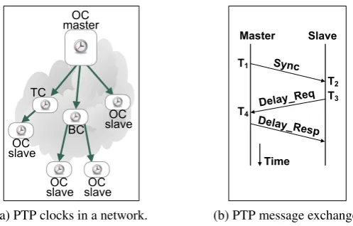
PTP is a protocol that allows the distribution of time and frequency over packet-switched networks. Three types of nodes are defined in PTP (see Fig. 2a); Ordinary Clocks (OC), Transparent Clocks (TC) and Boundary Clocks (BC). TCs and BCs are either switches or routers, whereas OCs are typically endpoints. An OC can either be a master or aslave. A master distributes information about its local time to slave clocks in the network using PTP messages.
The Best Master Clock Algorithm (BMCA) is used to elect the most accurate clock in the network as the master. A set of PTP clocks that synchronize to a common master forms a PTPdomain. A network may consist of several domains, where each domain is dominated by a different master.
A master periodically sends Sync messages to its slaves, incorporating information about its current time.Delay Request andDelay Responsemessages (see Fig. 2b) are used to measure the network delay between the master and slave. At the end of this message exchange the slave has four time values,T1,T2,T3andT4, as illustrated in Fig. 2b, allowing it to compute the offset,o, between its clock and the master’s clock as follows:
The parameterdMSis the delay between the master and the slave, and is given by:
dMS=
(T4−T1)−(T3−T2)
2 (2)
Sync and Delay messages are transmitted periodically, allowing slaves to synchronize to the
master’s clock based on multiple measurements of the o and dMS values. Each slave typically
uses a servo algorithm, which filters and combines multiple measurements of Eq. 1 and 2, and synchronizes the slave’s clock.
(a) PTP clocks in a network.
3 2
4 1
(b) PTP message exchange.
Figure 2. The Precision Time Protocol (PTP).
The usage of TCs and BCs in PTP is referred to ason-path support. A BC is a node that functions as a slave on one of its ports, and as a master on its other ports. TCs are simple intermediate nodes; they are neither masters nor slaves. Their role is to relay PTP protocol messages between the master and slaves, and to compute acorrection fieldfor each message. The correction field represents the aggregated internal delay of all the TCs on the path between the master and slave; when a TC relays a protocol message it measures the delay of the message from reception to transmission, and adds the value of this delay to the correction field. The slave can then use the correction field to eliminate the non-deterministic delays that result from the TCs’ transmission queues. Since TCs only compute the difference between the time of transmission and the time of reception, they are not required to synchronize their clocks to the master’s time. AsyntonizedTC is a TC that is frequency-synchronized to the master’s clock, allowing a more accurate correction field than when using a non-syntonized TC.
PTP supports two timestamping modes:one-step mode, where eachSync message includes its time of transmission,T1, andtwo-step mode, where aSync message is sent without a timestamp,
followed by aFollow-Upmessage that incorporates the timestampT1.
2.2. A Model for using Time in SDN
T(t) =t+o(t0) +ρ(t0)·[t−t0] +0.5·d·[t−t0]2 (3)
Heret0is some previous reference time value,o(t0) =T(t0)−t0is theoffsetat timet0, the clock skewatt0is denote byρ(t0), also known as the frequency error, anddis thedrift, which is the first
derivative of the skew. As in [25, 24], we assume that the drift,d, is constant.
Our system consists of n+1 nodes: a controllerc, and a set Sofnswitches.‡ We define two possibletimed operations:
•Timed notification: We define a setBof notifications that a switch can send to the controller. A notification sent to the controller indicates an event that occurred at the switch, and is accompanied by a timestamp, indicating whenthe event occurred. A switch can send a notification message of the formMsc(i,β,Ti)to the controller, denoting that the message includes a notificationβ∈B, and
a timestampTiin terms ofi’s clock.
• Timed command: We define a setA of possible commands that the controller can send to switches. The controller can send a timed command message to switchi, denoted byMcs(i,α,Ti), implying thatishould performα∈Aat timeTiin terms ofi’s clock.
TIMECONF(Te,AM)
1 fori∈Sdo 2 sendMcs(i,αi,Te)
Figure 3. A protocol for coordinated network updates.
A controller can use timed commands to invoke a coordinated action at multiple switches. TIMECONF[7], formally defined in Fig. 3, is a simple protocol for time-based updates, where the controller defines a single execution time,Te, for all switches,§andAM:={α1,α2, . . . ,αn}is a set
ofncommands, such that the controller assigns the actionαito switchifor eachi∈S.
3. REVERSEPTP: THEORY OF OPERATION
As described in Section 1.2, in REVERSEPTP a central node (the SDN controller) is the ‘brain’ of the network, and performs two main tasks: (i) running the PTP protocol as a slave separately with each of the SDN switches (which function as PTP masters), and (ii) performing the necessary translation between the masters’ times and the slave’s time. Each of these tasks is discussed in detail below.
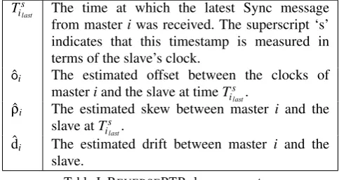
Running the PTP protocol.The REVERSEPTP slave is bound (concurrently and independently) tonREVERSEPTP masters. The slave exchanges PTP messages with each of the masters, and based on these messages maintains four parameters for each masteri:
‡Throughout the paper we assume that the controller is also the REVERSEPTP slave.
§The controller should take care to schedule an execution time that allows enough time for the update message to be sent
Ts
ilast The time at which the latest Sync message
from masteriwas received. The superscript ‘s’ indicates that this timestamp is measured in terms of the slave’s clock.
ˆ
oi The estimated offset between the clocks of
masteriand the slave at timeTis
last.
ˆ
ρi The estimated skew between master i and the
slave atTs ilast.
ˆdi The estimated drift between master i and the
slave.
Table I. REVERSEPTP slave parameters.
The offset ˆoi, the skew ˆρi, and the drift ˆdi, are computed by the slave based on the latest
measurement of Tilasts , as well as on previous measurements. Various well-known algorithms can be used for computing these two parameters, e.g., [25, 19].
Time translations.The parameters of Table I allow the slave to translate any timestampTs in terms of the slave’s clock to a timestampTi(Ts)in terms of masteri’s clock,¶or vice versa.
Notably, every timed operationthat can be performed in a clock-synchronized network is also possible in a REVERSEPTP-enabled network:
•Given atimed notificationreceived from masteriwith a timestampTi, the slave translatesTi
toTs(Ti)in terms of its local clock.
•When the slave invokes atimed commandthat needs to take place atTsin terms of the slave’s
clock, the slave translatesTstoTi(Ts), and usesTi(Ts)in the timed command message it sends to
masteri.
The following theorem presents the translation of Ti(Ts) and Ts(Ti), given the estimated parameters of Table I.
Theorem 1
Letts
ilast be the time at which the value of the slave’s clock isT s
ilast, and letoi(t s ilast),ρi(t
s
ilast), anddibe
the offset, skew and drift at timetilasts . Ifoi(tilasts ) =oˆi,ρi(tilasts ) =ρˆi, anddi=ˆdi, then:
(i) Ti(Ts) =Ts+oˆ
i+ρˆi·(Ts−Tilasts ) +0.5·ˆdi·(Ts−Tilasts )2, and
(ii) Ts(Ti) =Tilasts +−(1+ˆρi)+
q
(ˆρi+1)2+2ˆdi(Ti−Ts
i last−oˆi) ˆdi
Proof
We first prove(i). Sinceoi(ts
ilast) =oˆi,ρi(t s
ilast) =ρˆi, anddi=ˆdi, by Eq. 3 we obtain(i).
We now prove (ii). First, we observe that when the drift ˆdi is negligible, by (i) we have:
limˆdi→0Ti=Ts+oˆ
i+ρˆi·(Ts−Tislast). It follows that:
lim
ˆdi→0
Ts= T
i−oˆ
i+ρˆi·Tilasts
1+ρˆi
(4)
¶We use the notationTi(Ts), referring to the value of masteri’s clock at the time instant when the value of the slaves’s
Now, based on(i)we have:
Ti=Ts(1+ρˆi) +oˆi−ρˆi·Tilasts +0.5ˆdi(T s2−
2TsTilasts +Tilasts 2)
Reorganizing the terms we obtain:
0.5ˆdi·Ts2+ (1+ρˆi−ˆdi·Tislast)·T s
+oˆi−ρˆi·Tislast+0.5·ˆdi·T s ilast
2−Ti =0
We isolateTsby solving the quadratic equation above, and obtain:
Ts= 1
ˆdi
(ˆdi·Tislast−ρˆi−1)±
1 ˆdi
q
(ˆdiTilasts −ρˆi−1)2−2ˆdi(oˆi−ρˆiTilasts +0.5ˆdiTilasts 2−Ti),
and thus:
Ts= 1
ˆdi
(ˆdiTislast−ρˆi−1)±
1 ˆdi
q
(ρˆi+1)2+2ˆdi(Ti−Tislast−oˆi) (5)
The ‘±’ implies that there are two possible solutions. However, only one of these solutions is valid. We show this by observing the limit of the latter equation when ˆdi→0.
lim
ˆdi→0
Ts=lim
ˆdi→0
(ˆdiTislast−ρˆi−1)± q
(ρˆi+1)2+2ˆdi(Ti−Tilasts −oˆi)
ˆdi
Now, by applying L’Hˆopital’s rule to the latter, we obtain:
lim
ˆdi→0
Ts= lim
ˆdi→0
((ˆdiTislast−ρˆi−1)± q
(ρˆi+1)2+2ˆdi(Ti−Tislast−oˆi) )
0
(ˆdi)0
= lim
ˆdi→0
Tilasts ± 0.5·2·(T
i−Ts ilast−oˆi) q
(ρˆi+1)2+2ˆdi(Ti−Tislast−oˆi)
,
and thus:
lim
ˆdi→0
Ts= T
s
ilast(1+ρˆi)±(T i−Ts
ilast−oˆi)
1+ρˆi
(6)
By comparing Eq. 6 and Eq. 4, we conclude that from the two ‘±’ solutions, only the ‘+’ solution is valid, and thus by Eq. 5 we have:
Ts(Ti) =Tis
last+
−(1+ρˆi) +
q
(ρˆi+1)2+2ˆdi(Ti−Tislast−oˆi)
ˆdi
(7)
Intuitively, Theorem 1 states that if the slave’s estimated parameters areaccurate, thenTi(Ts)is given by (i), andTs(Ti)is given by (ii). Notably, Corollaries 2 and 3, which follow directly from
Corollary 2
For any timeTsmeasured in terms of the REVERSEPTP slave’s clock, the slave can estimate the
corresponding value of masteri’s clock by:
ˆ
Ti(Ts) =Ts+oˆi+ρˆi·(Ts−Tilasts ) +0.5·ˆdi·(Ts−Tilasts ) 2
(8)
Corollary 3
For any timeTi in terms of masteri’s clock, the slave can estimate the corresponding value of its clock by:
ˆ
Ts(Ti) =Tis
last+
−(1+ρˆi) +
q
(ρˆi+1)2+2ˆdi(Ti−Tislast−oˆi)
ˆdi
(9)
A first-order approximation. Interestingly, it is possible to use the following first-order approximation of Eq. 8, neglecting ˆρi·(Ts−Tilasts ) +0.5·ˆdi·(Ts−Tilasts )2:
ˆ
Ti(Ts) =Ts+oˆi (10)
This approximation is especially useful in cases whereTs−Tis
lastis negligible, i.e., when the timed
operation occurs close to the time at which the last Sync message was received.
4. THE REVERSEPTP PROFILE
In this section we show that REVERSEPTP can be defined as a PTP profile, i.e., as a subset of the features defined in the IEEE 1588 [13] standard. Significantly, since REVERSEPTP is defined as a subset of PTP, it follows that REVERSEPTP can be implemented by existing PTP-enabled switches. The REVERSEPTP profile has two interesting properties with respect to SDN: (i) to the extent possible it requires very simple functionality from the switches, and (ii) all PTP messages are exchanged between a controller and a switch, and thus no messages are exchanged between switches.
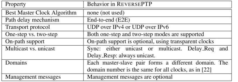
As per IEEE 1588 [13], the selected modes of operation of the REVERSEPTP profile are specified in Table II. We now briefly describe the set of attributes and modes that define this profile.
Property Behavior in REVERSEPTP Best Master Clock Algorithm none (not used)
Path delay mechanism End-to-end (E2E)
Transport protocol UDP over IPv4 or UDP over IPv6
One-step vs. two-step Both one-step and two-step modes are supported On-path support On-path support is optional, using transparent clocks Multicast vs. unicast Sync: either unicast or multicast. Delay Req and
Delay Resp: always unicast.
Domains Each master-slave pair forms a different domain. The domain number is the same for all clocks, as in [22] Management messages Management messages are optional
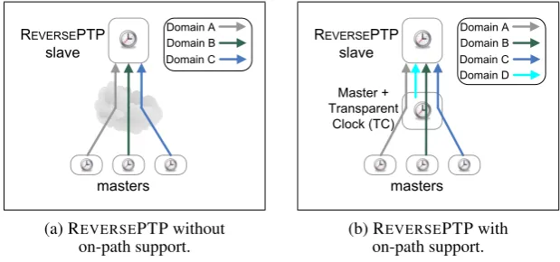
PTP domains.A set of PTP clocks that synchronize to a common master forms a PTPdomain. In REVERSEPTP, every switch forms a master-slave pair with the controller, in which the switch serves as master and the controller as slave; in particular, each master-slave pair forms a separate PTP domain (Fig. 4). When a slave receives a PTP message it identifies the packet’s domain based on its source address. Thus, as in [22], all domains can use the same domain number.k
masters REVERSEPTP
slave Domain B
Domain A
Domain C
(a) REVERSEPTP without on-path support.
masters REVERSEPTP
slave
Master + Transparent
Clock (TC)
Domain B Domain A
Domain C Domain D
(b) REVERSEPTP with on-path support.
Figure 4. REVERSEPTP: each master determines a separate domain.
On-path support. A PTP-enabled network may use Transparent Clocks (TC) or Boundary Clocks (BC), which are intermediate switches or routers that take part in the protocol, allowing high end-to-end accuracy. The usage of TCs or BCs is referred to as on-path support. On-path support in REVERSEPTP is optional. TCs may be used, allowing to improve the accuracy of the protocol using the PTPcorrection field[13]. This implies that a REVERSEPTP-enabled switch may function both as a master, distributing its time to the slave, and as a TC, which relays PTP messages from other Ordinary Clocks (Fig. 4b). For simplicity, BCs are not used in REVERSEPTP,footnoteNote that an
SDN can function as a ‘big BC’, as described in Section 5.3, but no BCs are used in REVERSEPTP domains. since a BC must, by definition, keep a synchronized clock and run a clock servo algorithm. It is interesting to note that if Transparent Clocks are used, they can be either syntonized [13] or non-syntonized. A syntonized TC is a TC that is frequency-synchronized to the master’s clock, allowing a more accurate correction field than a non-syntonized TC. Our centralized paradigm requires TCs to be as simple as possible, and hence non-syntonized; a non-syntonized TC is simply required to compute the residence time of en-route PTP messages, and is thus not required to run a complex servo algorithm. Moreover, TCs are not required to exchange PTP messages; a TC only udpates thecorrection fieldof en-route messages, indicating the internal latency of each message as it is transmitted through the TC. In Section 7.3 we briefly discuss how REVERSEPTP can be extended to allow syntonized TCs.
Best Master Clock Algorithm (BMCA).PTP uses the BMCA to choose a master. In contrast, REVERSEPTP does not use the BMCA; during the network initialization all switches are configured as masters and the controller is configured as a slave. This approach is aligned with the SDN paradigm, where a bootstrapping procedure (e.g., [26]) is typically used for configuring basic attributes, such as the controllers’ IP addresses.
Network Operating System S D N A p p -lic a ti o n
Control plane agent
Flow Table Flow Table Flow Table ... Controller Switch SDN protocol, e.g., OpenFlow S D N A p p -lic a ti o n S D N A p p -lic a ti o n
(a) Typical SDN architecture.
Network Operating System S D N A p p -lic a ti o n
Control plane agent
Flow Table Flow Table Flow Table ...
REVERSEPTP
Master
REVERSEPTP
Slave Controller
Switch SDN protocol,
e.g., OpenFlow PTP
timestamp conversion clock clock switch scheduling S D N A p p -lic a ti o n T im e d is t. a p p T im e -b a s e d u p d a te a p p
(b) REVERSEPTP-enabled SDN.
Figure 5. The REVERSEPTP architecture in SDNs: every switch runs a REVERSEPTP master, and the controller runs multiple REVERSEPTP slave instances. In an SDN that runs conventional PTP, a typical
approach would be for the controller to run a PTP master, and for each switch to be a PTP slave.
Unicast and multicast transmission. Sync messages in REVERSEPTP can be sent either as
unicast or as multicast. During network initialization, switches need to be configured with the controller’s unicast address. If multiple SDN controllers are used, Sync messages are distributed to a multicast address that represents the controllers. The operation of REVERSEPTP in SDNs with multiple controllers is further discussed in Section 7.4. Delay Request and Delay Response messages are always sent as unicast.
One-step vs. two-step.Both one-step and two-step modes can be used in REVERSEPTP.
Peer delay mechanism. The delay measurement mechanism in PTP has two possible modes of operation: End-to-End (E2E) mode, where delay request and response messages are exchanged between the master and slave, and Peer-to-Peer (P2P) mode, where intermediate TCs perform delay measurement on a one-hop basis. While the two modes can provide the same level of accuracy, P2P mode requires PTP messages to be exchanged between TCs. Hence, REVERSEPTP uses the E2E mode, as this paradigm implies that all delay messages are exchanged between a controller and a switch, and no messages need be exchanged between switches.
5. USING REVERSEPTP IN SDNS
5.1. TheREVERSEPTPArchitecture in SDN
A typical SDN architecture is illustrated in Fig. 5a. Thenetwork operating systemis a logical entity that manages the control plane of the network, and communicates with switches using an SDN protocol such as OpenFlow [12]. The controller may run one or moreSDN Application, a module that performs a network function such as routing or access control, using the SDN control plane. Every switch uses one or moreflow tables, which determine the switch’s data plane decisions, such as forwarding and security decisions. A switch’scontrol plane agentis responsible for managing the flow tables based on commands received from the controller.
Clocks. Every switch maintains a clock, which keeps the local wall-clock time and allows the switch to perform time-triggered actions and to timestamp notifications. REVERSEPTP does not require the switches’ clocks to be synchronized or initialized to a common time reference. The controller maintains a local clock. The controller’s clock is used as the reference for scheduling network-wide coordinated updates, and for measuring timestamped events. Thus, in some systems the controller’s clock may be required to be synchronized to an accurate external reference source such as a GPS receiver.
REVERSEPTP master. Each switch functions as a PTP master, and periodically sends Sync messages to the controller (its PTP slave), containing a local timestamp. We emphasize that the PTP master functionality is typically supported by existing implementations of PTP-enabled switches.
REVERSEPTP slave.The controller maintainsnREVERSEPTP slave modules, wherenis the number of switches in the network. Each slave module periodically receives Sync messages from one of the switches (its masters),i, and based on these messages it maintains the offset, skew, and drift ofiw.r.t. the controller’s clock (Table I).
Timestamp conversion.This module performs the required translation between the controller’s clock time and the switches’ clock time, as described in Section 3; a timestampTsin terms of the
controller’s clock, is translated into Ti in terms ofi’s clock using Eq. 8. Similarly, a notification from switchithat contains a timestampTi, can be converted to the controller’s timescale by Eq. 9.
It is a key observation that thetimestamp conversionmodule allows SDN applications that run at the controller to implement any time-based protocol that would require switches to be synchronized using a conventional synchronization protocol. This interesting property applies generally to SDN applications; coordination is not required directly between switches, but only through the controller. We now describe two interesting examples of SDN applications that use REVERSEPTP: the
time-based updateapplication, and thetime distributionapplication.
5.2. Time-based Updates usingREVERSEPTP
Time-based update application. This simple SDN application performs time-based network updates using the TIMECONF protocol (Fig. 3). When the application sends a time-based update, denoted byMcs(i,αi,Te), on line 2 of Fig. 3, thetime conversionmodule translatesTeto a timeTiin
the domain ofi’s clock.
Conceptually, the joint operation of the time-based update application and the timestamp
conversionblock performs the following protocol:
REVERSETIMECONF(Te,AM)
1 fori∈Sdo 2 Ti←T
e+oˆi+ρˆi·(Te−Tislast) +0.5·ˆdi·(Te−T s ilast)
2
3 sendMcs(i,αi,Ti)toi
Figure 6. Coordinated updates using REVERSEPTP.
As in Eq. 10, a first-order approximation of REVERSETIMECONF where line 2 is replaced by
Ti←Te+oˆi can be used when the higher order terms, ˆρi·(Te−Tilasts )and 0.5·ˆdi·(Te−Tilasts )2, are
Boundary Clock (BC)
(a) A conventional BC.
controller
switch 1
switch switch switch 2 master
slaves
Boundary Clock (BC) Software Defined Network
1 2
PTP REVERSEPTP
(b) An SDN as a ‘big BC’.
Figure 7. SDN as a Boundary Clock.
Switch scheduling. When switch i receives a scheduled message, Mcs(i,α,Ti), from the
controller, this module schedules the commandαto timeTiin terms of the switch’s local clock.
5.3. Time Distribution over SDNs usingREVERSEPTP
In some cases time must be distributed between end stations or networks that are attached to an SDN. For instance, an SDN-based mobile backhaul network must allow time distribution between base station sites, enabling the base stations to be synchronized. In this section we present an SDN application, denoted bytime dist. appin Fig. 5b, that allows time distribution over an SDN.
In conventional PTP-enabled networks time is distributed over one or more PTP Boundary Clocks (BCs) [13], as shown in Fig. 7a. A BC is a switch or a router that maintains an accurate clock based on Syncmessages that it receives from the PTP master, and distributes its time to the PTP slaves. When a BC receives a Sync message∗∗from the master (step 1 in Fig. 7a), its ingress time is accurately measured. Based on the Sync message and its ingress timestamp, the BC adjusts its clock. When the BC generates a Sync message to one of the slaves, the message is accurately timestamped when it is transmitted through the egress port (step 2 in Fig. 7a).
Our approach is illustrated in Fig. 7b; REVERSEPTP is used within the SDN, allowing the controller to maintain the time offset to each of the switches. An SDN is often viewed as a single ‘big switch’. Similarly, in our approach the SDN is a distributed BC that functions as a single logical ‘big BC’. When the master sends a Sync message, switch 1 accurately measures its ingress time,
T1 (step 1 in Fig. 7b), and sends the packet and T1 to the controller for further processing. The
controller convertsT1toTsusing thetimestamp conversionmodule, and thetime dist. app(Fig. 5b)
adjusts the controller’s clock based on the incoming Sync message and Ts. When the time dist. appsends a Sync message through switch 2, it uses the packet’scorrection field[13] to reflect the
offseto2 between switch 2 and the controller, and the packet is timestamped by switch 2 as it is transmitted (step 2 in Fig. 7b). This procedure can be implemented in OpenFlow [12], using Packet-In and Packet-Out messages between the controller and the switches. Note that there is currently no standard means for the ingress port of switch 1 to conveyT1to the controller. A similar problem has
been raised in the IEEE 1588 working group (e.g. [27]), and proposals that address it are currently under discussion there.
The significant advantage of the ‘big BC’ approach compared to the conventional PTP approach is that it enables the programmability of REVERSEPTP, while presenting standard PTP behavior to external non-SDN nodes.
6. EVALUATION
We have implemented a prototype of REVERSEPTP, based on the open-source PTPd [28], and evaluated its performance in a testbed with 34 nodes (Fig. 8).
The goals of our experiments were: (i) To evaluate the effectiveness of scheduling a simultaneous event in the network using REVERSEPTP, (ii) To verify that REVERSEPTP and conventional PTP provide a similar degree of accuracy under the same network conditions, and specifically, to verify that REVERSEPTP can schedule events with a high degree of accuracy using the approximation of Eq. 10, and (iii) To analyze the scalability of REVERSEPTP.
The experiments were conducted on the DeterLab testbed [29], where every testbed machine (computer) served as a PTP clock running the software-based PTPd. Note that our experiments used software-based PTP clocks in a network with up to two hops without on-path support, and we observed that the achievable accuracy in this software-based environment was on the order of tens to hundreds of microseconds.††
Accuracy measurement method. The accuracy of a set of clocks is typically measured in a controlled environment by connecting identical fiber cables from each of the clocks to a measurement device; each of the clocks transmits a 1 Pulse-Per-Second (1 PPS) signal to the measurement device, allowing the device to measure the offset between the clocks. Such a setting was not possible in the DeterLab testbed. Therefore, we measured the accuracy by using two types of time-triggered events, as described in the next subsection.
6.1. Time-triggered Events
This experiment included two scenarios: performing a time-triggered coordinated event, and recording a timestamped event. Both scenarios were implemented using REVERSEPTP, and we compare the results to an implementation of the same scenarios using PTP.
REVERSEPTP masters were implemented by running PTPd in master-only mode, with the BMCA disabled. Our n-slave REVERSEPTP node rann instances of PTPd in slave-only mode, each at a different PTP domain, using n PTP domain numbers. PTPd, when in slave mode, periodically provides the current Offset From Master. This value is typically used by the PTPd servo algorithm [19]. Our experiments used theOffset From Masteroutput to perform the first order approximation of Eq. 10.
Nodes 3 to 34 played the role of REVERSEPTP masters, node 1 was the REVERSEPTP slave, and node 2 served as a measurement probe. The experiment consisted of two parts:
(i) Coordinated event.We scheduled nodes 3 to 34 to send aPingmessage to node 2 at the same time. The scheduling was based on REVERSETIMECONFusing the offsets computed by node 1, the
DeterLab testbed REVERSEPTP
slave
REVERSEPTP masters
measurement probe
Ping
(a) Coordinated event: nodes 3 to 34 simultaneously sendPingmessage to node 2.
DeterLab testbed REVERSEPTP
slave
REVERSEPTP masters
measurement probe
Ping
(b) Timestamped event: node 2 sends broadcastPingmessage to nodes 3 to 34.
Figure 8. Network setup.
REVERSEPTP slave, with the approximation of Eq. 10. To simplify the experiment we did not use a control protocol such as OpenFlow. Instead, we used a simple doorbell-based method to distribute the scheduling to nodes 3 to 34; after the scheduling times were computed, they were written to the Network File System (NFS), and each of the nodes 3 to 34 read its scheduling time from the NFS. In node 2 we monitored the distribution of the Pingmessage arrival times; the arrival time of each packet was captured by Wireshark [30] using the machine’s Linux clock. Interestingly, this experiment is the message-based variant of a 1 Pulse Per Second (PPS) signal sent from each of the 32 clocks to a single testing device.
We repeated the experiment with PTP instead of REVERSEPTP, using TIMECONF(Fig. 3). The distribution of the arrival times of the 32Pingmessages at node 2 is illustrated in Fig. 9a. The value ‘0’ on the time axis represents the median of the arrival times. As shown in Fig. 9a, the arrival times were spread over a period of about 8 milliseconds.
In Section 3 we observed that the approximation of Eq. 10 is valid whenTs−Tilasts is negligible. In our experiments, the Ping messages were scheduled to be sent 15 seconds in the future, and hence
Ts−Tilasts was on the order of 15 seconds. The results show that 15 seconds is a sufficiently low
value to allow Eq. 10 to produce an accurate approximation.
(ii) Timestamped event.We sent a broadcastPingmessage from node 2 to nodes 3 to 34, and measured its arrival times to each of these nodes using Wireshark. We then used Eq. 10 to align the reception times to a common REVERSEPTP-based time reference. We repeated the experiment using conventional PTP. The empirical PDF of the arrival times measured at nodes 3 to 34 is depicted in Fig. 9b. Notably, the distribution of the arrival time in this experiment provides a rough estimate of the clock accuracy; since the BroadcastPingmessage is replicated and distributed by the testbed’s hardware switches, we expect very low delay variation among the replicas. Thus, Fig. 9b provides an estimate of the clock accuracy.
We observed that in the coordinated event experiment the time elapsed from when the Ping
-8 -3 2 7
Ping Arrival Time [milliseconds] ReversePTP PTP
(a) Coordinated event: PDF of thePing
arrival time when nodes 3 to 34 send a
Pingto node 2 simultaneously.
-0.15 -0.05 0.05 0.15 0.25
Ping Arrival Time [milliseconds] ReversePTP
PTP
(b) Timestamped event: PDF of thePing
arrival time when node 2 sends a broadcast
Pingto nodes 3 to 34.
Figure 9. Accuracy measurements of a coordinatedPing. The timestamped event experiment (b) provides a rough estimate of the clock accuracy.
explaining the fact that the arrival time in Fig. 9a ranges over a period of about 8 milliseconds, a significantly wider range than the one shown in Fig. 9b.
The experiment demonstrates how REVERSEPTP can be effectively used to coordinate events, or to accurately measure the occurrence time of events. It shows that REVERSEPTP provides the same level of accuracy as the conventional PTP.
6.2. Scalability
In the second experiment we studied the scalability aspects of REVERSEPTP, with an emphasis on the load placed on a REVERSEPTP slave compared to a conventional PTP master.
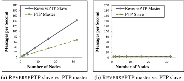
Rate of protocol messages.Fig. 10 compares the protocol message rate of REVERSEPTP with that of conventional PTP. The Sync rate in our experiments was 1 Sync message per second, with a Delay Req message rate of 1 per second as well. We used two-step mode, and thus Follow Up messages were used as well. We ran the experiment for a duration of 100 seconds.
0 20 40 60 80 100 120 140 160 180 200
0 10 20 30
M es sa g es p er S ec o n d
Number of Nodes ReversePTP Slave
PTP Master
(a) REVERSEPTP slave vs. PTP master.
0 20 40 60 80 100 120 140 160 180 200
0 10 20 30
M es sa g es p er S ec o n d
Number of Nodes ReversePTP Master
PTP Slave
(b) REVERSEPTP master vs. PTP slave.
Figure 10. REVERSEPTP vs. PTP: rate of PTP messages sent or received by each node.
Sync and Follow Up were multicast messages, whereas in REVERSEPTP all messages were unicast. The fact that some of the messages were sent as multicast allowed the conventional PTP to use roughly half the number of messages used by REVERSEPTP.
0.0001 0.001 0.01 0.1 1 10 100
0 10 20 30
C P U U ti li z a ti o n [ % ]
Number of Nodes Type I Type II
(a) REVERSEPTP scalability: CPU utilization of a REVERSEPTP slave. 0.0001 0.001 0.01 0.1 1 10 100
0 10 20 30
C P U U ti li z a ti o n [ % ]
Number of Nodes Type I Type II
(b) PTP scalability: CPU utilization of a PTP master.
0.0001 0.001 0.01 0.1 1 10 100
0 10 20 30
C P U U ti li z a ti o n [ % ]
Number of Nodes
ReversePTP
PTP
(c) TIMECONFscalability: CPU utilization of a controller running TIMECONFon a Type II machine.
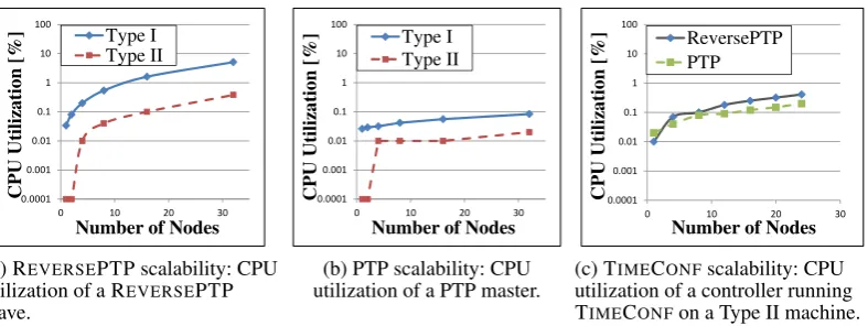
Figure 11. CPU Utilization in REVERSEPTP and in PTP as a function of the number of nodes. The figures are presented for two machines types: Type I is a low performance machine, and Type II is high performance.
CPU Utilization. A more important metric of scalability is CPU utilization. We analyzed the difference between REVERSEPTP and PTP in terms of the percentage of the CPU that is utilized by the PTP process. We repeated the experiment for two types of machines: Type I, a Dual Core AMD Opteron, running at 1.8 GHz, and Type II, an Intel Xeon E3 LP, running at 2.4 GHz. Note that the two types we chose are at the extremes of the performance scale; at the time of the experiment Type II was the most powerful machine in the DeterLab testbed, while Type I was the least powerful one. The CPU utilization measured on REVERSEPTP masters and PTP slaves (i.e., switches in
an SDN environment), was negligible, well below 0.1% on both machine types. A significantly higher utilization was measured on PTP masters and REVERSEPTP slaves (controllers in an SDN environment), as illustrated in Fig. 11a and 11b. These two figures illustrate the CPU utilization of the PTPd process as a function of the number of nodes, either REVERSEPTP masters or PTP slaves. As expected, the CPU utilization of the REVERSEPTP slave (Fig. 11a) is significantly higher than that of the PTP master (Fig. 11b), since the REVERSEPTP slave runsnservo algorithm instances. Nevertheless, REVERSEPTP consumes only 5% of the resources of machine Type I, and significantly less than 1% of the resources of the more powerful Type II.
Fig. 11c provides some insight into the effect of REVERSEPTP on an SDN application such as the TIMECONFprotocol. The figure illustrates the CPU utilization of an SDN controller running REVERSETIMECONF vs. an SDN controller running TIMECONF with the conventional PTP. In the experiment we used the time-enabled OpenFlow prototype of [8]; the controller sent timed update messages to the switches at a rate of 1 message per second. The figure illustrates the CPU utilization as a function of the number of SDN switches. Only the utilization of the SDN controller task was considered in Fig. 11c, without considering the PTP task. As shown in the figure, REVERSETIMECONFyields higher CPU load, as each timed message sent by the controller requires the time conversion of line 2 of Fig. 6.
7. DISCUSSION
7.1. Accuracy
The clock accuracy in a network depends on a number of factors, including the accuracy of the timestamping mechanisms, the quality of the clock oscillators, and whether on-path support is used. As discussed in the Introduction, given the same network characteristics we expect REVERSEPTP and PTP to provide the same degree of accuracy. The experimental evaluation of Section 6 confirmed that REVERSEPTP, even with the approximation of Eq. 8, can provide an accuracy that is comparable to that of conventional PTP.
As stated in Section 4, the REVERSEPTP paradigm implies that TCs are non-syntonized. Although the IEEE 1588 standard does not specify that TCs must be syntonized, syntonized TCs have been shown [31] to provide a higher degree of accuracy, especially over a large number of hops. A possible extension to REVERSEPTP that mitigates this limitation is discussed in Section 7.3.
7.2. Scalability-Programmability Tradeoff
The experimental evaluation in Section 6.2 showed that REVERSEPTP loads the SDN controller’s resources more than traditional PTP. This emphasizes a tradeoff that is at the heart of SDN; the controller takes on tasks that are traditionally performed by switches in non-SDN networks, allowing high flexibility and programmability, at the cost of controller resources. The experiments show that although REVERSEPTP requires more resources than conventional PTP, the REVERSEPTP scheme can easily scale to networks with thousands of SDN switches.
7.3. Synchronizing Clocks usingREVERSEPTP
The concept we presented does not require switches to be synchronized to a common wall-clock time. However, REVERSEPTP can be extended to allow switches to be time-synchronized. PTP allows masters to query slaves about the master-slave offset using PTP management messages. Using these messages in REVERSEPTP, switches can synchronize their clocks with the controller’s
clock. Note that the offset only allows switches to get a first-order approximation, as per Eq. 10. It is possible to extend PTP to allow slaves to periodically send the three parametersTs
ilast, ˆoi, and
ˆ
ρi, allowing REVERSEPTP masters to maintain an accurately synchronized clock. Note that this
extension allows switches to be synchronized at the cost of additional complexity and message exchanges. The main benefit of this approach compared to the conventional PTP is that the algorithmic logic is centralized and programmable.
The latter extension can similarly be used to allow syntonized TCs; a non-syntonized TC may perform less accurate updates of the correction field due to its inaccurate frequency, whereas a TC that periodically receives the three parameters above can use these parameters to accurately compute the correction field, using well-known methods (e.g., [31]).
7.4. REVERSEPTPin an SDN with Multiple Controllers
REVERSEPTP allows each slice to be managed according to a different time reference, by allowing each controller to be synchronized to a different reference source. Notably, this slicing property is exclusive to REVERSEPTP, and is not possible in conventional clock synchronization methods. Time distribution to multiple controllers can be performed efficiently by using a multicast group that consists of the controllers, thereby reducing the rate of PTP messages, since each switch sends its Sync messages to the multicast group. Moreover, when the controllers act in an active-standby mode, the switches only need to distribute their time to the currently active controller.
7.5. Security aspects
The potential security vulnerabilities of REVERSEPTP are similar to those of conventional synchronization protocols [32, 33]. In PTP, a successful attack results in one or more slaves not being accurately synchronized to the correct time, whereas in REVERSEPTP, a successful attack causes the controller to have an inaccurate view of the offset to one or more of the switches. An application that requires accurate time is similarly affected in both cases.
8. CONCLUSION
Clock synchronization protocols are not ‘one size fits all’, as different applications may have different requirements and constraints. We introduced REVERSEPTP, a clock synchronization scheme suitable for SDN. While REVERSEPTP is tailored for SDN, it can be valuable in many other centralized and software-controlled architectures, such as industrial automation systems [3], power-grid networks [34], and various network-managed applications [35, 36]. REVERSEPTP provides the same level of accuracy as conventional synchronization protocols, including PTP, while its novel architecture shifts the complex functionality from the switches to the controller, facilitating the agility and programmability that are of key importance in SDNs.
ACKNOWLEDGMENT
The authors would like to thank Wojciech Owczarek for his dedicated help and support with PTPd. We gratefully acknowledge the DeterLab project [29] for the opportunity to perform our experiments on the DeterLab testbed. This work was supported in part by the ISF grant 1520/11.
REFERENCES
1. ITU-T G.8271/Y.1366, “Time and phase synchronization aspects of packet networks,” 2012.
2. J. C. Corbettet al., “Spanner: Google’s globally distributed database,”ACM Transactions on Computer Systems (TOCS), vol. 31, no. 3, p. 8, 2013.
3. K. Harris, “An application of IEEE 1588 to industrial automation,” inIEEE ISPCS, 2008.
4. IEEE, “Time-Sensitive Networking Task Group,”http://www.ieee802.org/1/pages/tsn.html, 2012. 5. P. Moreira, J. Serrano, T. Wlostowski, P. Loschmidt, and G. Gaderer, “White rabbit: Sub-nanosecond timing
distribution over ethernet,” inIEEE ISPCS, 2009.
6. Open Networking Foundation, “OpenFlow-enabled mobile and wireless networks,”ONF Solution Brief, 2013. 7. T. Mizrahi and Y. Moses, “Time-based updates in software defined networks,” inACM SIGCOMM workshop on
8. T. Mizrahi and Y. Moses, “Software defined networks: It’s about time,” inIEEE INFOCOM, 2016.
9. T. Mizrahi, E. Saat, and Y. Moses, “Timed consistent network updates in software defined networks,”IEEE/ACM Transactions on Networking (ToN), 2016.
10. T. Mizrahi and Y. Moses, “Time-based Updates in OpenFlow: A Proposed Extension to the OpenFlow Protocol,” technical report,http://tx.technion.ac.il/˜dew/OFTimeTR.pdf, 2013.
11. N. McKeownet al., “OpenFlow: enabling innovation in campus networks,”SIGCOMM Comput. Commun. Rev., vol. 38, pp. 69–74, Mar. 2008.
12. Open Networking Foundation, “OpenFlow switch specification,”Version 1.5.0, 2015.
13. IEEE TC 9, “1588 IEEE Standard for a Precision Clock Synchronization Protocol for Networked Measurement and Control Systems Version 2,” 2008.
14. H. Li, “IEEE 1588 time synchronization deployment for mobile backhaul in China Mobile,” keynote presentation, IEEE ISPCS, 2014.
15. D. Mills, J. Martin, J. Burbank, and W. Kasch, “Network time protocol version 4: Protocol and algorithms specification,”RFC 5905, IETF, 2010.
16. T. Mizrahi and Y. Moses, “Using REVERSEPTP to distribute time in software defined networks,” inIEEE ISPCS, 2014.
17. T. Mizrahi and Y. Moses, “REVERSEPTP: A software defined networking approach to clock synchronization,” in ACM SIGCOMM workshop on hot topics in software defined networks (HotSDN), 2014.
18. D. Veitch, J. Ridoux, and S. B. Korada, “Robust synchronization of absolute and difference clocks over networks,” IEEE/ACM Transactions on Networking (TON), vol. 17, no. 2, pp. 417–430, 2009.
19. K. Correll, N. Barendt, and M. Branicky, “Design considerations for software only implementations of the IEEE 1588 precision time protocol,” inConference on IEEE 1588, pp. 10–12, 2005.
20. Y. Zhao, J. Liu, E. Lee,et al., “A programming model for time-synchronized distributed real-time systems,” in IEEE Real Time and Embedded Technology and Applications Symposium (RTAS), 2007.
21. P. Derler, J. C. Eidson, S. Goose, E. A. Lee, S. Matic, and M. Zimmer, “Using PTIDES and synchronized clocks to design distributed systems with deterministic system wide timing,” inIEEE ISPCS, 2013.
22. ITU-T G.8265.1/Y.1365.1, “Precision time protocol telecom profile for frequency synchronization,” 2010. 23. J. Y. Halpern, B. Simons, R. Strong, and D. Dolev, “Fault-tolerant clock synchronization,” inPODC, pp. 89–102,
ACM, 1984.
24. T. Srikanth and S. Toueg, “Optimal clock synchronization,”Journal of the ACM (JACM), vol. 34, no. 3, pp. 626– 645, 1987.
25. D. L. Mills, “Improved algorithms for synchronizing computer network clocks,”IEEE/ACM Transactions on Networking (TON), vol. 3, no. 3, pp. 245–254, 1995.
26. Open Networking Foundation, “OpenFlow management and configuration protocol (of-config 1.2),” 2014. 27. R. Tse and C. Ong, “Proposal for a standardized mechanism to transfer timing information from an ingress port to
an egress port of a PTP transparent clock,” ISPCS, special session on proposed revisions of IEEE 1588-2008, 2012. 28. PTPd, “Precision Time Protocol daemon,”version 2.3.0,http://ptpd.sourceforge.net/, 2013.
29. The DeterLab project, http://deter-project.org/about_deterlab, 2015. 30. Wireshark, http://www.wireshark.org/, 2014.
31. G. M. Garner, “Effect of a frequency perturbation in a chain of syntonized transparent clocks,” technical report, IEEE 802.1, 2007.
32. T. Mizrahi, “Time synchronization security using IPsec and MACsec,” inIEEE ISPCS, 2011.
33. T. Mizrahi, “Security requirements of time protocols in packet switched networks,” RFC 7384, IETF, 2014. 34. B. Dickerson, “Time in the power industry: how and why we use it,” Arbiter Systems, technical report,http:
//www.arbiter.com/ftp/datasheets/TimeInThePowerIndustry.pdf, 2010.
35. T. Mizrahi and Y. Moses, “OneClock to rule them all: Using time in networked applications,” inIEEE/IFIP Network Operations and Management Symposium (NOMS) mini-conference, 2016.