Vol. 04, Issue 03 (March. 2014), ||V6|| PP 55-60
PLC Based PID Speed Control System
Avinash P. Kaldate
1, Sachin A. Kulkarni
21
(Assistant Professor,Sinhgad college of engineering,Vadgaon(B.K.),Pune)
2
(Associate Professor, Sinhgad college of engineering,Vadgaon(B.K.),Pune)
Abstract: - In this paper, an intelligent controller of AC Motor drive designed using proportional-integral-derivative (PID) optimization for the optimal tuning of PID controller parameters. A PID controller control loop feedback mechanism controller widely used in Industrial control system. A optimization algorithm is employed in order to obtain the controller parameters assuring deadbeat response at each selected load. The AC-Motor PID-controller is modeled in SLC 500. The response of the developed controllers is compared to that of the controllers whose parameters are tuned using the Ziegler-Nichols method. The developed methodology is more proficient in improving the controller loop response stability, the steady state error, the rising time and overshoot and hence the disturbances do not affect the performances of AC-motor.
Keywords: - Control System, Mechatronics , PLC,PID
I. INTRODUCTION
Control system design and analysis technology are widely suppress and very useful to be applied n real time development some can be solved by hardware technology and by the advance use d for software, control system are analyzed easily and detailed .The implementation of PID is based on the digital design. These digital PID include many algorithms to improve their performances such as anti wind up auto-tuning, adaptive, fuzzy fine tuning.
Induction motor is the most widely used motor for appliances, industrial control and Automation hence they are often called the workhorse of the motion industry. They are most reliable and durable. When power is supplied to the motor with recommended. It runs at its rated speed. However many application needs variable speed operations for example a washing machine, many use different speed for each washing cycle. Conventionally mechanical gear systems were used to obtain variable speed. Electronic power and control systems have matured to allow there components to be used for motor control in place of mechanical gears. These electronic not only control the motor speed but can improve the motor dynamics and steady state characteristics.
Induction motor control is complex due to its non linear characteristics. While there are different methods for control variable frequency is most common method of speed control in close loop. Method is most suitable for applications without position control requirements or the need of high accuracy of speed control. Example of these application including air conditioning, fan and blowers .v/f control can be implemented by using PID based PLC control system. The speed of induction motor can be adjusted to great extent so as to provide easy control and high performance. Several conventional and numerical controller type intended for controlling AC motor speed at its executing various task PID controller, fuzzy logic controller or the combination between them: PID-practical swarm optimization, PID-Neural Network, PID –Genetic algorithm, PID-ant colony optimization and optimal fuzzy logic controller using the different strategy.
PID controller is widely used in industrial plants because it is simple and robust. Industrial process is subjected to variation in parameters and parameter perturbations, which when significant make the system unstable. So the control engineers are on look for automatic tuning procedure.
II. SYSTEMDESIGN
1.Hardware stucture:
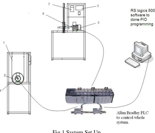
Fig.1.System Set Up
1. Spring weight to control torque 2. Flywheel 3. Digital speed indicator 4. Proximity sensors 5. 3-phase induction motor. 6. Universal joint. 7. Variable frequency drive.
Fig.2.Basic Diagram of PLC
As shown in Fig.1, the whole system consists of three different units. The first unit is the PC. The PC runs a program called RS LOGIX 500, which is used to configure the hardware, the software package as shown in
Fig.2 and write a control program for the PLC. This control program is downloaded to the PLC through the Ethernet PC Adapter communication cable. The second unit is the PLC it consist of analogue input and output .The last unit is on variable frequency drives . This unit is located on the outer part of the control centre and is connected directly to the device to be controlled.
The Programmable Logic Controller (PLC). Typically, the basic functional components of a PLC system are a processor unit, memory, power supply unit, input/output interface section, communications interface, and programming device. Fig. 2. shows the basic arrangement.
The processor unit or central processing unit (CPU) is the unit containing the microprocessor. This interprets the input signals and carries out the control actions, according to the program stored in its memory, communicating the decisions as action signals to the outputs.
The power supply unit is needed to convert the mains AC voltage to the low DC voltage necessary for the processor and the circuits in the input and output interface modules.
The programming device is used to enter the required program into the memory of the processor. The program is developed in the device and then transferred to the memory unit of the PLC.
The memory unit is where the program for the microprocessor is stored. The memory unit also stores input data from for processing and buffers data for output.
might be connected to motor starter actuators. Input and output devices can be classified by signal type, such as digital or analogue.
The communications interface is used to receive and transmit data on communication networks. It manages device verification, data acquisition, synchronization between user applications, and connection management.
In this study used a Allen Bradley Compact PLC which has 24 DIs (Digital Inputs), 16 DOs (Digital Outputs), 5 AIs (Analogue Inputs), 2 AOs (Analogue Outputs), and a power supply (120/230 V AC, 24 V DC, 5 A).
Fig.3. Snap Shot of PID Implimentatation
2. Software Structure
The software for the control system was developed in the RS LOGIX 500. This is the central window which becomes active when the software is started. The default setting starts the Wizard, which assists the programmer to create a project. Programmers can select the programming mode: ladder diagram (LAD), function block diagram (FBD), and instruction list . The project structure is used to store and arrange all the data and programs in order. The system software was completed in four steps. Step 1 designs the solution to the automation task. Step 2 configures the hardware and the network. Step 3 creates the program in ladder diagram form. Step 4 transfers the program to the CPU. Finally, the software is tested for input status, program execution, and output status.
III. SYSTEM IMPLEMENTATION
Fig.4.Flow Chart of PLC programming
1.Programming setup
Programming has been done on the Allen-Bradley PLC. The analog input given to the PLC is in the unscaled manner so it need to convert into the scaled manner that will possible by converting in the format of 0-4095 resolution. If the input of the PLC is the ON then converted to 0-4095 an if it is OFF then it is converted to 0. Motor speed control is the task within the set point limit of speed 0 to 1400 rpm whether the input used to plc changes from 4 to 20 mA and output ranges from the 0 to 4095.
PID block consist of control block, process variable, control variable and control block length. Control block include kp , ki & kd values and set point limit values. Following steps are taken for PID programming on PLC RUNG 1. Proximity sensor count stored into the system which fitted on the shaft of motor.
RUNG 2.Total senses converted into how many senses done into the one sec.
RUNG 3. Total count in one sec is multiplied by the 60 which gives speed of the motor in rpm. RUNG 4. RPM move into the PID block as process value which compare with setpoint. RUNG 5. PID block gives provision to fill the values of kp, kd & ki and also enter the set point. RUNG 6.PID output converted into percentage output of total range in scp block.
2. Experimental setup
Fig.5.actual experimental setup
3.Experimental result
Following results are plotted on RPM of the motor vs. time in sec at different proportional constant (kp).Here set point put at 520 RPM. Measured RPM at 10 sec interval each as we move towards maximum kp value the accuracy level of the system increases. Here some time required to control motor speed as we change the torque of the rope brake dynamometer. The range of the speed variation different due to different proportional value.
IV. CONCLUSIONS
PID controllers can work surprisingly well, especially considering how little information is provided for the design. Several methods for tuning the controllers have been presented. There can be vast differences in the results produced by different tuning procedures. The quality of the tuning is very much dependent on the compatibility of the tuning method with the plant behavior and the performance goals. The control system can be easily implanted in other PLC´s Finally, it is important to mention that we prepared the software modular structure to accept changes of the control strategies. It can be easily adapted to meet the user’s individual application needs, and can be tailored to their present and future needs.
REFERENCES
[1] L. A. Bryan and E. A. Bryan, Programmable Controller Theory and Implementation second edition (670-766)
[2] E. E. El-kholy, A. M. Dabroom and Adel E. El-kholy Adaptive Fuzzy Logic Controllers State of the art J. Electrical Systems 2-3 (2006): 116-145
[3] Jaime Fonseca , Joao L. Afonso, Julio S. Martins, Carlos Couto, Fuzzy logic speed control of an induction motor, Microprocessors and Microsystems 22 (1999) 523–534.
[4] Turki Y. Abdalla, Haroution Antranik Hairik and Adel M. Dakhil, Direct Torque Control System for a Three Phase Induction Motor With Fuzzy Logic Based Speed Controller, Iraq j. Electrical and Electronic Engineering Vol.6 No.2,2010.
[5] Vinod Kumar, R.R.Joshi, Hybrid Controller based Intelligent Speed Control of Induction Motor, Journal of Theoretical and Applied Information Technology