Journal of Engineered Fibers and Fabrics 148 http://www.jeffjournal.org Volume 10, Issue 4 – 2015
An Experımental Study Of RC Beams Wıth
Varyıng Concrete Strength Classes Externally
Strengthened Wıth CFRP Composıtes
Turgay Cosgun
Department of Civil Engineering, Faculty of Engineering, Istanbul University, Istanbul TURKEY
Correspondence to:
Turgay Cosgun email: [email protected]
ABSTRACT
It is known that the vast majority of buildings in Turkey are made out of reinforced concrete (RC). The 1999 Kocaeli and Düzce, the 2010 Elazığ, and the 2011 Van earthquakes that occurred in Turkey revealed that the most significant factor in causing damage to buildings, or their collapse, was the use of low quality concretes, i.e., concretes with low strength values, in their construction. This reveals that the load bearing members of these structures should be reinforced against the effects of possible earthquakes. The aim of the present study is to investigate the effect of carbon fiber reinforced polymer (CFRP) usage on the behavior of beams made out of low strength concrete. Within the scope of the study, the results of the experimental and numerical analysis for 14 RC beams, to which CFRP plates were applied on their lower surface, as well as for two reference beams, were presented for the case of collapsing. From the start of the test to the end, load, deflection and deformation data obtained from the beams were collected and then, by the identification of the collapsing mechanism as well as the load-deflection relation, the behavior of the beams was discussed in detail. In the numerical study, moment capacities were obtained for CFRP applied beams with different concrete strength values by using the material properties of the specimens examined in the mechanical test. The results of the numerical analysis were compared with those of the experimental tests, which were found to be consistent with each other.
Keywords: Carbon fiber reinforced polymer (CFRP),
RC beam, adhesive, deformation, deflection, concrete strength class.
INTRODUCTION
The main reason for building collapse and damage caused by four large earthquakes experienced recently in Turkey, i.e., Kocaeli and Düzce-1999,
Elazığ-2010 and Van-2011, was the use of poor quality concrete in the structural members [1-3]. This revealed that the load bearing parts of existing buildings should be reinforced against any possible earthquake. For this purpose, the effectiveness of the traditional use of carbon fiber reinforced polymer (CFRP) reinforcement on low concrete strength members should be examined. In the parts where high tensile loads exist, reinforced concrete (RC) members, such as beams, slabs, and columns, are strengthened by high strength fiber reinforced polymer (FRP). In order to bond them, an epoxy resin is frequently used. As a result of the applied load, two main boundary conditions appear, that is the usability and final load bearing capacity [4].
Strengthening against flexure can be achieved by the application of CFRP to the load bearing members where tensile stresses exist. Similarly, if CFRP is wrapped around these members, strengthening against shearing can be achieved. According to the Turkish Earthquake Code [5], the external addition of stirrup and wrapping by a fibrous polymer is advised to improve the shear loading capacity of members. However, the method, which was advised for beams in this code, was not suitable for the improvement of flexural capacity.
Journal of Engineered Fibers and Fabrics 149 http://www.jeffjournal.org Volume 10, Issue 4 – 2015
the ultimate strain following the yielding of reinforcing steel rebar in tension; iii) Shear failure: The shear cracks extend from the vicinity of the support to the loading point, when the shear capacity of the beam is exceeded; iv) Concrete cover separation failure: After crack initiation at the CFRP strip end, the CFRP strip is gradually peeled off with lumps of concrete detached from the longitudinal steel rebar; v) Plate end interfacial debonding; vi) Intermediate flexural or flexural-shear crack induced interfacial debonding (otherwise known as IC debonding): Delamination of the CFRP strip occurs catastrophically in an unstable manner, with a thin layer of concrete residue attached to the delaminated FRP sheets. The crack initiates from the end of FRP strips or the bottom of a flexural or shear/flexural crack in the concrete member; vii) Shear induced debonding (can be referred to as critical diagonal crack debonding or CDC debonding).
In the literature, there are experimental, analytical and numerical studies on the repairing and strengthening of RC beams by CFRP. RC beams strengthened or repaired by CFRP against flexural and shear effects were tested by subjecting them to monotonic or cyclic loadings [9-12]. Major types of failure observed in these experiments are the rupture of the CFRP, the crushing of the concrete, and the separation of the concrete cover [13-15]. It was proven by the experimental data that the thickness of the CFRP and distance of CFRP from the supports were decisive on the type of the failure. Within this scope, there are designs to determine the minimum and maximum thicknesses of FRP so that rupture of the FRP plates and the yielding of the reinforcing bars can be avoided [16]. Meanwhile, in the collapse of the plate tip and that of the aperture, the type of the adhesive, the length and width of the plate, as well as the rigidity of the plate can be effective [6,17]. In many studies, the use of U-shaped steel strips were advised to prevent the removal of the FRP plate tip while it was detected that for the prevention of the crack growth, w-shaped strips were more effective [18,19].
Investigation of the interfacial stresses is a method used in the determination of the flexural and shear behavior of the CFRP-strengthened beams. Finite element analysis and experimental verifications were performed for this purpose. These studies demonstrated that apart from the type of the adhesive, the dimensions of the CFRP were also effective on cross-sectional stresses. It was detected that as the
beam length and FRP thickness increased, these stresses also increased. However, the difference in the dimensions of the beam did not make a significant impact [20-22].
It is possible to repair and even strengthen the damaged beams by FRP. Generally, if RC beams are damaged and then strengthened by FRP, the final load-bearing capacity increases. However, in this case, the failure occurs in a brittle manner [23, 24]. When CFRP is applied to damaged beams and then axial loads are applied, the use of CFRP is beneficial for the reduction of crack widths and increasing axial stiffness [25]. The number of layers in the FRP and the number of FRP in high strength flexural RC beams are the other issues being investigated [26]. In FRP strengthened RC beams, the amount of reinforcement was found to be effective. It was found that the maximum increase in the flexural strength was obtained with moderate numbers of reinforcements [27-29].
Although the orientation of fibers is effective on failure, the stiffness and strength of the beams, the use of suitable adhesive has a profound effect on the final capacity. Meanwhile, cement based chemicals and fasteners were also frequently used in the utilization of carbon fiber [30-33]. Apart from these, in order to reduce the inferior effects of shear forces, anchorage systems were used at the tip of the FRP which converted the shear failure to ductile failure [34].
In order to determine the behavior of the FRP-strengthened beams, numerical models were frequently used along with the experimental data. In these models, the flexural capacity of the beam, the flow of the composite, and types of failures were under investigation [14, 35, 36]. Additionally, there are models examining the interfacial bonding strength between the concrete and FRP [37].
Journal of Engineered Fibers and Fabrics 150 http://www.jeffjournal.org Volume 10, Issue 4 – 2015
In this study, strengthening of the load bearing members, more specifically beams, frequently used in the existing RC buildings were examined. For this purpose, different concrete strength classes and rebar arrangements were investigated by experimental and numerical methods. Sixteen RC beams, including two control beams, were subjected to four-point bending until complete failure. For these beams, ultimate load bearing capacities, load-displacement curves and load-deformation relations were determined and compared with each other. In the numerical part of the study, moment capacities of the beams were obtained by using the properties of the beams used in the experimental part. After numerical analysis the results were compared with those of the experimental data.
Within this scope, the aim of this study was to investigate the use of CFRP on the beams made out of low strength concrete. By identifying the load-bearing and mechanical behaviors of this combination, some suggestions on strengthening of RC beams were made.
Experimental Investigation
Within the scope of the experimental study, a total of 16 RC beams were produced in two series, i.e., eight flexural beams (FB) and eight shear beams (SB). The beams had dimensions of 150×150×750mm and two 2φ10 reinforcements were used longitudinally in both compressive and tensile regions. The φ8 reinforcement was utilized as a stirrup. The details of the flexural and shear beams are shown in Figure 1.
FIGURE 1. The details of the beam series: (a) Flexural beams (FB), (b) Shear beams (SB).
For RC beams, three strength classes, C8, C14 and C20, and one reinforcement class, S420, were identified (see Table I for details). From among 16 RC beams, two of them were not reinforced by CFRP
and are referenced as control beams. The remaining 14 RC beams were reinforced by CFRP plates which were applied to the parts of the beams where tensile forces had formed during loading. Before utilization of the plates, strain gauges were mounted to each beam to determine the deformations in the concrete and the plates. In the flexural beams, an attempt was made to avoid shear collapse by using a higher numbers of stirrups compared to shear beams.
TABLE I. Material properties of the specimens.
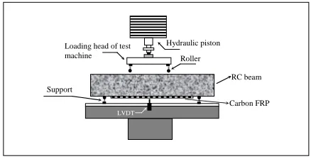
In the experimental part, a four-point bending test was used to deform sample beams (see Figure 2 for a schematic drawing of the set-up). For this purpose, the beams were first located on two supports which were 600mm apart from each other. Then, the beams were loaded symmetrically by two loading heads located between supports. There was a 600mm distance between supports and a 200mm distance between heads. As schematically shown in Figure 2, a linear variable displacement transducer (LVDT) was also mounted to the middle of the beam so as to measure the displacement in the RC beams.
Loading head of test machine
Hydraulic piston
Carbon FRP
LVDT
Support
Roller
RC beam
FIGURE 2. The experimental set-up and its instrumentation.
Preparation of the Experimental Components
Preparation of RC Beams
Journal of Engineered Fibers and Fabrics 151 http://www.jeffjournal.org Volume 10, Issue 4 – 2015
used in the concrete mixtures. As-casted RC beams were held within the mold for two days, after which they were removed. Note that the quality of the concrete was measured by performing compression tests on cubic concrete samples, each having an edge length of 200mm. The compression test was conducted on the concrete samples after allowing them to cure for 28 days.
Five strain gauges were mounted on the RC beam samples. As may be seen in Figure 3, one of these gauges was mounted on a compression surface, one on a tensile surface, and three on a side surface. It should be noted that, before mounting the gauges, the surfaces were smoothed using emery paper and cleaned with a vacuum cleaner as well as acetone. In order to attach the gauges on the clean surfaces, first a thin layer of a mixture of two different epoxy binders was spread on the surfaces. The gauges were then attached to the RC beams. The mounted gauges sat for one day to allow for complete cure.
FIGURE 3. The application of strain gauges on beam FB06.
Preparation of CFRP
In all CFRP strengthened beams, SikaCarboDurS1012 type CFRP plates, supplied from Sika Co., were used. The plates were 550mm in length, 100mm in width and 1.2mm in thickness, (Table II). In order to bond the CFRP plate on RC beams, Sikadur-30 epoxy resin, a product of Sika Company, was used (see Table III for the mechanical properties of the adhesive).
TABLE II. Dimensions and material properties of FRP.
TABLE III. Mechanical properties of Sikadur-30 adhesive.
Before application of the adhesive to the RC beams, the surface roughness was removed using emery paper and then the beams were cleaned with a vacuum cleaner. Epoxy adhesive, with a uniform 1mm thickness, was applied to these surfaces. After adhesion of the CFRP plates to the epoxy layer, they were left for complete cure. To enhance this, a steel plate was left on the CFRP plates, see Figure 4.
FIGURE 4. The application of CFRP on the lower surface of the beams.
A special tape was used to prevent the interaction between strain gauges mounted on the lower surface of the beams and the epoxy used to bond the CFRP plates. The wire of the strain gauge present on the tensile surface of the RC beam was passed through a small hole opened into the CFRP plate. In this way, squeezing of the wire between the CFRP plate, epoxy adhesive and the RC beam was avoided. Meanwhile, the wire was transferred to the external surface without any damage.
Numerical Study
Journal of Engineered Fibers and Fabrics 152 http://www.jeffjournal.org Volume 10, Issue 4 – 2015
flexural capacities were determined via flexural analysis. In the analysis, it was assumed that there was a full-composite motion between the CFRP and the RC beam. In the numerical calculations, the formulations and coefficients given in the Eurocode 2 Standard were used.
As can be seen in Figure 5, the user interface of the FRP-Analysis software has different input sections for flexural strengthening mode, which define the properties of the components of the FRP reinforced beam and its loading conditions. These sections are the type of cross-section (rectangular beam or T-beam), cross-section geometry of beam (width, height), concrete strength class (C) or its mean strength (fcm), elastic modulus of FRP (Ef), limiting strain of FRP (εf,lim), area (As), position (d) and yield stress (fyk) of the steel reinforcement, bending moment during strengthening (Mo), required design moment after strengthening (Msd) and acting moment (Mser,r).
FIGURE 5. The interface of the FRP-Analysis Software.
The software allows the determination of the moment using an equivalent pressure block approach through balancing compressive and tensile forces (see Figure 6). As seen in Figure 6, the balance of internal forces in a FRP-strengthened RC beam is expressed as follows:
f f f s s s s
ck b x A f A f A E
f ε
α⋅ ⋅ ⋅ + 2⋅ 2 = 1⋅ 2+ ⋅ ⋅
(1)
FIGURE 6. Tensile block approach used in the FRP-Analysis Software.
In Eq. (1), the strength of the beam and strength of the reinforcement in the compressive region are shown on the left side of the equation. The right side on the other hand, includes the strength of the reinforcement in the tensile region as well as the effect of FRP. Considering the balance of tensile and compressive forces, the moment capacity (Mrd) of the strengthened beam could be found by:
(2)
Results of the Experimental and the Numerical Study
Results of the Experimental Study: Evaluation of the Deformation Data
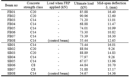
In the experimental study, the applied load and corresponding strain formed on the beams were measured by means of six strain gauges mounted on the samples. The data were transferred to a data logger and used to determine the load-deformation relation. The ultimate load and corresponding mid-span deflection values of all specimens are given in
Table IV.
Journal of Engineered Fibers and Fabrics 153 http://www.jeffjournal.org Volume 10, Issue 4 – 2015
By using the deflection value, time-strain graphs were also drawn. Figure 7 and Figure 8 show the variation of deformation values for beams FB02 and SB04, respectively. As seen from the figures, the different faces of beams behaved differently upon loading. For example, the middle of the side face was not deformed at all. However, on the up and down surfaces of the concrete, deformation increased continuously until maximum load and then decreased. A similar behavior was also detected by gauges mounted on the side-down, side-up parts as well as the one mounted on CFRP.
FIGURE 7. The variation of strain with time for beam FB02.
FIGURE 8. The variation of strain with time for beam SB04.
Results of the Experimental Study: Comparison of the Results
The Comparison of the Failure Modes
For all beams, the bending experiment was ended when the failure load was reached. After the completion of the experiments, the failure modes of the specimens were investigated. Table V
demonstrates the failure modes of the flexural and shear beams examined in the present study.
TABLE V. Failure modes of the flexural and shear beams.
The examination of the specimens point out that in flexural, shear and control beams, the failure occurred in a similar way. For all beams in flexural series and shear series, the failure mode is shearing. However, there are some exceptions. For example, in the control beam in the bending series, FB08, there were flexural cracks as well as shear cracks (see
Figure 9). Its different behavior pointed to the fact that the CFRP altered the mechanical behavior of the RC beams and their failure mode. Similarly, in some shear beams, there was also plate end debonding in addition to shear failure. This can be clearly seen in
Figure 10, which shows the end plate debonding failure of the specimen SB05.
FIGURE 9. Flexural and shear cracks formed in FB08 beam upon loading.
Journal of Engineered Fibers and Fabrics 154 http://www.jeffjournal.org Volume 10, Issue 4 – 2015
Load-Deflection Relation of Beams with Same Concrete Strength Class
The load-deflection curves of the selected flexural and shear beams with a concrete strength class of C14 are given in Figure 11. As seen from Figure 11a, the ultimate load capacities and deflection values of the selected flexural beams, i.e., FB03, FB04 and FB05, were in close proximity to each other. While the deflection values of these beams were nearly the same with the deflection value of the control beam, FB08, their ultimate load capacity values were much higher due to CFRP strengthening. Meanwhile, beams, especially FB04 and FB05, demonstrated much higher rigidity when compared to the control beam. Different from the control beam, in these selected flexural beams, first the maximum load was reached and then the load was released as a result of the shear cracks. In the last stage, deflection increased steadily until the failure (see Figure 11a).
FIGURE 11. Comparison of load–deflection (P-δ) curves for strengthened beams and control beams: (a) FB Series, (b) SB Series.
The examination of load-deflection curves given in
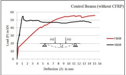
Figure 11b shows that the selected beams (SB01, SB04 and SB05) display some differences in terms of their mechanical behavior when compared to the control beam (SB08). For example, it was seen that the selected beams demonstrated more ductile behavior than did the control beam. Meanwhile, all the selected beams had ultimate load capacities higher than the ultimate load capacity of the control
beam, 73kN, 77kN and 67kN for SB01, SB04 and SB05 respectively and 55kN for the control beam. As seen in Figure 11b, the control beam is very rigid under the initial loading while after a 1 mm deflection it could be deformed up to 14mm. This ductile behavior of the control beam SB08 could be attributed to the fact that the beam had a concrete strength class of C14.
Load-Deflection Relation of Beams with Different Concrete Strength Class
The load-deflection curves of the selected flexural and shear series beams with different concrete strength classes (C14 and C20) are shown in Figure 12.
FIGURE 12. Comparison of load–deflection (P-δ) curves for strengthened beams; (a) FB Series, (b) SB Series.
Journal of Engineered Fibers and Fabrics 155 http://www.jeffjournal.org Volume 10, Issue 4 – 2015
both SB02 and SB03 beams (C20 concrete strength class) had ca. 89kN ultimate load bearing capacity, C14 concrete strength class beams, i.e., SB01 and SB07, had 73kN and 78kN load bearing capacities, respectively.
It should be noted that reinforcing by CFRP was an effective way to strengthen RC beams of different concrete strength classes. The experimental study indicated that this statement holds for both flexural and shear beams, see Figure 12. As seen in the figure, FB and SB beams of the same concrete strength class had close values of ultimate load bearing capacities and deflections.
Load-Deflection Relations for Different Rebar Arrangements
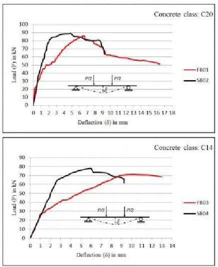
For the sake of clarity, it is important to compare the mechanical behavior of the beams with different rebar arrangements. For this reason, beams with different rebar arrangements but the same concrete strength classes were compared with each other. These results are shown in Figure13. Figure13a
shows the load-deflection curves of C20 concrete class beams, FB01 and SB02, and Figure13b shows the load-deflection curves of C14 concrete class beams, FB03 and SB04. Meanwhile, the load-deflection curves for control beams are also shown in
Figure 14 for comparison with reinforced beams.
FIGURE 13. Comparison of load–deflection (P-δ) curves for strengthened beams; (a) for C20 class, (b) for C14 class.
The load-displacement curves given in Figure 13
allow the comparison of many mechanical properties of beams with different rebar arrangements but the same concrete strength classes. Firstly, the graphs indicate that the flexural beams demonstrated a more ductile behavior when compared with shear beams of the same concrete class. For example, the overall deflection value of FB01 is almost two times higher than that of SB02. This is also valid for C14 concrete strength class beams. As a result of the higher ductility values, these beams possessed higher energy absorbing capability.
Secondly, it can be stated that the type of rebar arrangement did not affect the load bearing capacity of the reinforced beams, i.e., reinforced beams with different rebar arrangements but the same concrete strength classes had similar load bearing capacities. As seen in Figure 13, C20 class beams have ultimate load bearing capacities of nearly 90kN, and C14 class beams have nearly 77kN, regardless of the rebar arrangement. Apart from these, the graphs indicate that the deflection properties of beams of different rebar arrangements are also different from each other. As was revealed in both C20 and C14 class beams, shear beams demonstrated more elastic behavior at the beginning of the deformation. For example, in C14 class beams, the elastic deflection is almost 3mm for SB04, while for FB03 it was only 1mm. In the course of the deformation, the difference of the deflection values was also observed. It was also shown that shear beams reached their ultimate load bearing capacities at lower deflection values. This can be clearly seen in both C20 class and C14 class beams where, for example, the deflection value was 10mm for SB04, while it was only 6mm for FB03.
Journal of Engineered Fibers and Fabrics 156 http://www.jeffjournal.org Volume 10, Issue 4 – 2015
FIGURE 14. Comparison of load–deflection (P-δ) curves for control beams.
Load-deformation Relation at Different Concrete Strengths
The load-deformation relationship for examined flexural and shear beams with C14 and C20 concrete strength classes are given in Figures 15 and 16.
FIGURE 15. Load-deformation relation for beams FB02 and FB04.
FIGURE 16. Load-deformation relation for beams SB03 and SB04.
As seen from Figure 15, a C20 class beam, FB02, demonstrated more ductile behavior and possessed higher energy absorbing capability than a C14 class beam, FB04. While these two beams had similar
elastic behavior at the beginning of the loading, their behaviors differed significantly in the course of the deformation. As revealed in Figure 15 after ultimate load capacity was reached, the load released and the deformation in the beam FB02 decreased steadily until failure. By contrast, when the load was released in FB04, the deformation carried on for some time.
The load-deformation behaviors of the shear beams of SB03 and SB04 with concrete strength classes of C14 and C20 are given in Figure 16. Examining the graphs, it can be stated that C20 class concrete had properties superior to those of the C14 class in terms of ductility, energy absorption, and deformability. Different from flexural beams, both the C14 and C20 class shear beams experienced a decrease in the deformation when the ultimate load was reached (see
Figure 16).
Comparison of the Experimental Data with Numerical Results
Moment values obtained in both the numerical study and the experimental work are given in Table VI. As can be seen from the table, for CFRP strengthened C20 class flexural and shear beams, there was approximately a 7% difference between the numerical and the experimental results. However, for C14 and C8 concrete strength class beams, this difference was only 2% and 5%, respectively. For control beams, the difference was nearly 5%.
TABLE VI. Moment values obtained in both numerical study and experimental work.
Considering the scope of the numerical and experimental study, as well as the results obtained, the following recommendations can be made:
Journal of Engineered Fibers and Fabrics 157 http://www.jeffjournal.org Volume 10, Issue 4 – 2015
(2) The study indicates that CFRP could be effectively utilized on the low strength beams. Thus, CFRP can be applied to the C8 and C14 class load-bearing members of the buildings already present.
(3) An experimental study should be conducted in order to determine to what extent the utilization of the CFRP on the damaged RC beams is effective. For this purpose, it is necessary to apply CFRP to the damaged beams with different concrete strength classes.
CONCLUSION
There are many experimental, numerical and theoretical studies on the strengthening of RC beams with CFRP. Some of these studies have dealt with load-bearing members in the structures which might be affected by an earthquake. It is known that in the construction of buildings, C8 and C14 class RC beams were commonly used before the 1999 Kocaeli Earthquake. The present study offers new insight into this field in the way that it has investigated these load bearing members. In this study, the effectiveness of the strengthening of the RC beams by CFRP was investigated experimentally and numerically. In order to make a comprehensive analysis, 16 RC beams, with different concrete strength classes, C8, C14 and C20, and different reinforcement layouts, flexural and shear, were examined. In the numerical part of the study, the moment capacities of the beams were obtained and compared to the experimentally found values.
The results of the experimental and numerical studies are summarized below:
(1) As demonstrated experimentally, the CFRP strengthened flexural (FB) and shear (SB) beams showed very close ultimate load-bearing capacities.
(2) In flexural (FB) and shear (SB) beams, the use of CFRP on the C14 class RC beam increased its ultimate load capacity by about 37%.
(3) In all CFRP strengthened flexural beams, shear failure was observed. The increase in the rigidity of the central region was probably the underlying reason for the shear failure. In the shear beams however, there was plate end debonding in addition to shear failure. This indicates that the reinforcement layout had a strong effect on the formation of plate end debonding.
(4) The load-deflection curves of C14 class flexural and shear beams demonstrated that CFRP strengthened beams had almost equal deflection values and possessed similar ductility.
(5) Load-deflection curves of the beams showed that C20 and C14 class beams had similar ductility, deflection and load-deformation behaviors. This demonstrates that CFRP has a similar effect on the load-displacement behavior of the beams with different concrete strength classes.
(6) Load-deflection curves indicated that CFRP strengthened C20 class flexural and shear beams had higher rigidity, lower deflection and lower ultimate load bearing capacity than CFRP strengthened C14 beams. The comparison of C20 and C14 class flexural and shear beams demonstrated that the application of CFRP increased the rigidity to a higher extent for flexural beams when compared with the shear beams.
(7) If the load-deflection curves of the CFRP strengthened beams are examined, it can be seen that the C20 concrete strength class beam has a higher ductility than the C14 concrete strength class beam. Thus, the C20 class beam has higher deformability.
(8) It was found that the ultimate load bearing capacity and ductile behavior of CFRP strengthened flexural and shear beams with different reinforcement layouts were similar, while their failure mechanisms were different.
(9) The difference between the results of the numerical analysis and experimental study are in the range of 2-7%. It can be concluded that the difference is at an acceptable level and the results are consistent with each other.
ACKNOWLEDGMENTS
Journal of Engineered Fibers and Fabrics 158 http://www.jeffjournal.org Volume 10, Issue 4 – 2015
REFERENCES
[1] Scawthorn, C., Johnson, G. S., Preliminary Report Kocaeli (Izmit) Earthquake of 17 August 1999, Engineering Structures, 2000; 22 (7), 727-745.
[2] Celep, Z., Erken, A., Taskin, B., Ilki, A., Failures of Masonry and Concrete Buildings during the March 8, 2010 Kovancılar and Palu (Elazığ) Earthquakes in Turkey, Engineering Failure Analysis, 2011; 18 (3), 868-889.
[3] Damcı, E., Bekdas, G., Temur, R., Sayin, B., Preliminary Technical Report on October 23th, 2011 Van Earthquake, (In Turkish), http://www.istanbul.edu.tr/muh/insaat/20111 023van, (2011).
[4] Fib Bulletin, Externally Bonded FRP
Reinforcement for RC Structures, Technical Report, (2001).
[5] Turkish Earthquake Code for Buildings, Specification for Buildings to be Built in Earthquake Areas, Ministry of Public Works and Resettlement, Ankara, Turkey, (2007). [6] Gao, B., Leung, C. K. Y., Kim, J. K., Failure
Diagrams of FRP Strengthened RC Beams”, Composites Structures, 2007; 77(4), 493-508.
[7] Eurocode 2, Concrete Structures Code,
Eurocode for the Design of Structures, (1993).
[8] Turkish Standards 500, “Requirements for Design and Construction of Reinforced Concrete Structures”, Turkish Standards Institute, Ankara, Turkey, (2001).
[9] Balamuralikrishnan, R., Jeyasehar, A., Flexural Behavior of RC Beams Strengthened with Carbon Fiber Reinforced Polymer (CFRP) Fabrics, The Open Civil Engineering Journal, 2009; 3, 102–109. [10] Kachlakev, D., McCurry, D. D., Behavior of
Full-Scale Reinforced Concrete Beams Retrofitted for Shear and Flexural with FRP Laminates, Composites Part B-Engineering, 2000; 31 (6-7), 445-452.
[11] Obaidat, Y. T., Heyden, S., Dahlblom, O.,
Abu-Farsakh, G., Abdel-Jawad, Y.,
Retrofitting of Reinforced Concrete Beams using Composite Laminates, Construction and Building Materials, 2011; 25 (2), 591-597.
[12] Wang, Y. C., Lee, M. G., Chen, B. C., Experimental Study of FRP Strengthened RC Bridge Girders subjected to Fatique Loading, Composites Structures, 2007; 81 (4), 491-98.
[13] Saadatmanesh, H., Malek, A. M., Design Guidelines for Flexural Strengthening of RC Beams with FRP Plates, Journal of Composites and Construction, 1988; 2 (4), 158-164.
[14] Aprile, A. and Benedetti, A., Coupled Flexural-Shear Design of R/C Beams Strengthened with FRP, Composites Part B-Engineering, 2004; 35 (1), 1-25.
[15] Nardone, F., Lignola, G. P., Prota, A., Manfredi, G. and Nanni, A., Modeling of Flexural Behavior of RC Beams Strengthened with Mechanically Fastened FRP Strips, Composites Structures, 2011; 93 (8), 1973-1985.
[16] Almusallam, T. H.and Al-Salloum, Y. A., Ultimate Strength Prediction RC Beams Externally Strengthened by Composite Materials, Composites Part B-Engineering, 2001; 32 (7), 609-619.
[17] Camata, G., Spacone, E., Zarnic, R,
Experimental and Nonlinear Finite Element Studies of RC Beams Strengthened with FRP Plates, Composites Part B-Engineering, 2007; 38 (2), 277-288.
[18] Rasheed, H. A., Pervaiz, S., Closed Form Equations for FRP Flexural Strengthening Design of RC Beams, Composites Part B-Engineering, 2003; 34 (6), 539-550.
[19] Sobuz, H. R., Ahmed, E., Sutan, N. M., Hasan, N. S., Uddin, A., Uddin, J., Bending and Time-Dependent Responses of RC Beams Strengthened with Bonded Carbon Fiber Composite Laminates, Construction and Building Materials, 2012; 29 (April-2012), 597-611.
[20] Chen, G. M., Chen, J. F., Teng, J. G., On the Finite Element Modelling of RC Beams Shear-Strengthened with FRP, Construction and Building Materials, 2012; 32 (July-2012), 13-26.
[21] Maalej, M., Bian, Y., Interfacial Shear Stress Concentration in FRP-Strengthened Beams, Composites Structures, 2001; 54 (4), 417-426.
[22] Maalej, M., Leong, K. S., Effect of Beam Size and FRP Thickness on Interfacial Shear Stress Concentration and Failure Mode of FRP-Strengthened Beams, Composites Science and Technology, 2005; 65 (7-8), 1148-1158.
Journal of Engineered Fibers and Fabrics 159 http://www.jeffjournal.org Volume 10, Issue 4 – 2015
[24] Rabinovitch, O., Frostig, Y., Experiments and Analytical Comparison of RC Beams Strengthened with CFRP Composites, Composites Part B-Engineering, 2003; 34 (8), 663-677.
[25] Ferretti, D., Savoia, M., Non-linear Model for R/C Tensile Members Strengthened by FRP-Plates, Engineering Fracture Mechanics, 2003; 70 (7-8), 1069-1083.
[26] Akbarzadeh, H., Maghsoudi, A. A.,
“Experimental and Analytical Investigation of Reinforced High Strength Concrete Continuous Beams Strengthened with Fiber Reinforced Polymer”, Materials and Design, 2010; 31 (3), 1130-1147.
[27] Esfahani, M. R., Kianoush, M. R., Tajari, A. R., Flexural Behaviour of Reinforced Concrete Beams Strengthened by CFRP Sheets, Engineering Structures, 2007; 29 (10), 2428-2444.
[28] Ashour, A. F., El-Refaie, S. A., Garrity, S. W., Flexural Strengthening of RC Continuous Beams using CFRP Laminates, Cement and Concrete Composites, 2004; 26 (7) 765-775.
[29] El-Ghandour, A. A., Experimental and
Analytical Investigation of CFRP Flexural and Shear Strengthening Efficiencies of RC Beams, Engineering Failure Analyses, 2011; 25 (3), 1419-1429.
[30] Aprile, A., Feo, L., Concrete Cover Rip-off of R/C Beams Strengthened with FRP Composites, Composites Part B-Engineering, 2007; 38 (5-6), 759-771. [31] Norris, T., Saadatmanesh, H., Ehsani, M. R.,
Shear and Flexural Strengthening of R/C Beams with Carbon Fiber Sheets, Journal of Structural Engineering-ASCE, 1997; 123 (July-1997), 903-911.
[32] Saadatmanesh, H., Ehsani, M. R., Fiber Composite Plates can Strengthen Beams, American Concrete Institute, Concrete International, Design and Construction, 1990; 12 (3), 65-71.
[33] Hashemi, S., Al-Mahaidiv, R., Experimental and Finite Element Analysis of Flexural Behavior of FRP-Strengthened RC Beams using Cement-based Adhesives, Construction and Building Materials, 2012; 26 (1), 268-273.
[34] Bencardino, F., Spadea, G., Swamy, R. N., The Problem of Shear in RC Beams Strengthened with CFRP Laminates, Construction and Building Materials, 2007; 21 (11), 1997-2006.
[35] Zaid, R. Z., Negheimish, A. I., Al-Saawani, M. A., El-Sayed, A. K., Analytical Study on RC Beams Strengthened for Flexure with Externally Bonded FRP Reinforcement, Composites Part B-Engineering, 2012; 43 (2), 129-141.
[36] Kim, G., Sim, J., Oh, H., Shear Strength of Strengthened RC Beams with FRPs in Shear, Construction and Building Materials,
2008; 22 (6), 1261-1270.
[37] Chen, J. F., Teng, J. G., Shear Capacity of FRP-Strengthened RC Beams: FRP Debonding, Construction and Building Materials, 2003; 17 (1) 27-41.
[38] Wenwei, W., Guo, L., Experimental Study and Analysis of RC Beams Strengthened with CFRP Laminates under Sustaining Load, International Journal of Solids and Structures, 2006; 43 (6), 1372-1387.
[39] FRP-Analysis Program, A Software for the Design with Sika CarboDur Composite Strengthening Systems to Increase the Flexural, Shear and Confinement Strength of Reinforced Concrete Structures, Based on the fib Bulletin 14, version 1.0, Department of Civil Engineering, University of Patras, Greece, (2008).
AUTHORS’ ADDRESS Turgay Cosgun
Istanbul University
Department of Civil Engineering Avcilar Campus