IJEDR1703101
International Journal of Engineering Development and Research (
www.ijedr.org
)
708
Vibration Control of Framed Structure Using Tuned
Mass Damper
Saurabh Chalke
1, Prof P.V. Muley
21PG Student, 2 Assistant Professor 1 Department of Civil Engineering,
1 Datta Meghe College of Engineering, Navi Mumbai, Maharashtra, India
________________________________________________________________________________________________________ Abstract—The current and modern constructions demands taller structures but these taller structures should have the
adequate self weight because at the time of Earthquake the self weight of structure plays the essential role. Due to which structure should design and built with minimum possible weight but still we can’t minimize the sections to reduce the self weight as it will affect the safety criteria of sections therefore the alternative to control the vibration while Earthquake and wind excitation is by installing damper in the structure, to minimize the vibration and stabilize the structure under the dynamic condition. The passive tuned mass damper is widely used to control the harmonic and wind excitation. This paper represents the vibration control of framed structure using tuned mass damper by using Etabs 2015. The study deals with the analysis of G+51 storey structure without damper and with tuned mass damper and the comparison of the displacement and drift values under the dynamic condition.
Index Terms- Earthquake, Wind Excitation, Tuned Mass Damper,Response Spectrum Analysis, Etabs
________________________________________________________________________________________________________
I.INTRODUCTION
The most of structural system designed to carry vertical load may not have the capacity to resist lateral load or even if it has, the design of lateral load will increase the structural cost substantially with increase in number of storey. As the seismic load acting on a structure is a function of the self-weight of the structure these structures are made comparatively light and flexible which have relatively low natural damping. Results make the structures more vibration prone under wind, earthquake loading. New generation high rise building is equipped with artificial damping device for vibration control through energy dissipation. The various vibration control methods include passive, active, semi-active, hybrid. Various factors that affect the selection of a particular type of vibration control device are efficiency, compactness and weight, capital cost, operating cost, maintenance requirements and safety [2]. A Tuned mass damper is a passive damping system which utilizes a secondary mass attached to a main structure normally through spring and dashpot to reduce the dynamic response of the structure. The secondary mass system is designed to have the natural frequency, which is depended on its mass and stiffness, tuned to that of the primary structure. When that particular frequency of the structure gets excited the TMD will resonate out of phase with the structural motion and reduces its response. Then, the excess energy that is built up in the structure can be transferred to a secondary mass and is dissipated by the dashpot due to relative motion between them at a later time. Mass of the secondary system varies from 1-10% of the structural mass. As a particular earthquake contains a large number of frequency content now a day’s multiple tuned mass dampers has been used to control earthquake induced motion of high rise structure where the more than one TMD is tuned to different unfavorable structural frequency [3].
The Etabs 2015 is a finite-element-based structural program for the analysis and design of civil structures. It offers an intuitive, yet powerful user interface with many tools to aid in the quick and accurate construction of models, along with the sophisticated analytical techniques needed to do the most complex projects. Etabs 2015 has proven to be the most integrated, productive and practical general purpose structural program on the market today. Complex models can be generated and meshed with powerful built in templates. Etabs 2015 is an easiest and most productive solution for our structural analysis and design needs.
II.METHODOLOGY
A tuned mass damper (TMD) is a device consisting of a mass, a spring, and a damper that is attached to a structure in order to reduce the dynamic response of the structure. The frequency of the damper is tuned to a particular structural frequency so that frequency is excited, the damper will resonate out of phase with the structural motion. Energy is dissipated by the damper inertia force acting on the structure.
IJEDR1703101
International Journal of Engineering Development and Research (
www.ijedr.org
)
709
III.MODELLING DETAILS
Structural Details
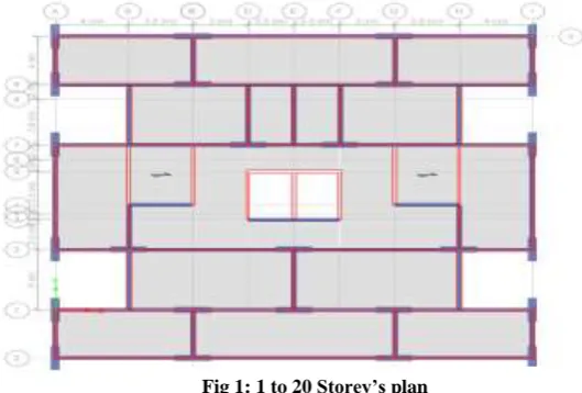
For the analysis work ,model of concrete frame building (G+51) floors are made to know the realistic behaviour of building during earthquake. The length of the building at ground is 27 m and 26 m. The typical storey height is 4 m.
Grade of Concrete M 45 For Columns and M40 For Beams
Grade of Reinforcing Steel HYSD 415
Dimension of Beam 250×600 mm
Dimension of Column 1 to 20 storey: 500 X 2000 mm
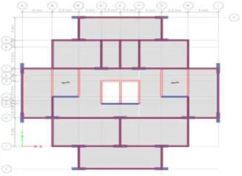
20 to 34 storey: 500 mm X 1800 mm 35 to 51 storey: 500 mm X 1600 mm
Thickness of Slab Floor Slab :- 150mm
Staircase Slab :- 200 mm
Height of Typical Storey 4 m
Dead Load Dead load according to IS 875 part I
Live Load Live load according to IS 875 part II
Wind Load Wind load according to IS 875 part III
Earthquake Load Criteria as per IS 1893: 2002
Zone IV Site Type III
Density of Concrete 25 KN/m3
Seismic Intensity Very Severe
Response Reduction Factor 5
Zone Factor 0.36
Damping Ratio 5%
Structural Class C
Wind Speed Zone 5
Basic Wind Speed 55 m/s
Risk Coefficient 1.00
Wind Design Code IS 875:1987 (Part 3)
RCC Design Code IS 456:2000
Steel Design Code IS 800:2007
Load Combinations As per IS 1893:2002 (part 1) and IS 456:2000
Location of Damper For Top 8 Storey’s (From 43 to 51)
IJEDR1703101
International Journal of Engineering Development and Research (
www.ijedr.org
)
710
Fig 2: 20 to 34 Storey’s plan
Fig 3: 34 to 51 storey’s plan
IJEDR1703101
International Journal of Engineering Development and Research (
www.ijedr.org
)
711
Damper DetailsThe tuned mass damper used is the distributed type of tuned mass damper i.e. instead of using long pendulum with huge mass, tuned mass damper is divided into small distributed pendulum mass damper each of having mass of 100 kg , installed for top eight storey at outer face on both side of building.
Fig 5: Design of Tuned mass Damper [5]
Properties of Tuned Mass Damper:- Length of Damper = 0.9 m
Mass Attach to the Damper =100 kg
Location of Damper = for top eight storey’s indicated by black in Fig 4: 3D sketch of the structure
IV.RESULT AND DISCUSSION
The results have been shown for most critical condition and for the critical load combination. Considering the wind speed as 55 m/s, therefore wind is found to be governing factor.
1. Comparison of Displacement and Drift values without Damper and with Damper
Load Case :-EQX
Displacement Graph
0 20 40 60 80 100 120 140 160 180
Sto
ry
51
Sto
ry
48
Sto
ry
45
Sto
ry
42
Sto
ry
39
Sto
ry
36
Story
33
Sto
ry
30
Sto
ry
27
Sto
ry
24
Sto
ry
21
Sto
ry
18
Sto
ry
15
Story
12
Sto
ry
9
Sto
ry
6
Sto
ry
3
p
lint
h
Displacement Graph for Eqx (mm)
Maximum Displacement without Damper:-159.295 Maximum Displacement with Damper: - 131.434
IJEDR1703101
International Journal of Engineering Development and Research (
www.ijedr.org
)
712
Load Case :- EQY
0 0.0002 0.0004 0.0006 0.0008 0.001 0.0012 Sto ry 51 Sto ry 48 Sto ry 45 Sto ry 42 Sto ry 39 Sto ry 36 Sto ry 33 Sto ry 30 Sto ry 27 Sto ry 24 Sto ry 21 Story 18 Sto ry 15 Sto ry 12 Sto ry 9 Sto ry 6 Story 3 p lint h 0 20 40 60 80 100 120 140 160 180 200 Sto ry 51 Sto ry 48 Sto ry 45 Sto ry 42 Story 39 Sto ry 36 Sto ry 33 Sto ry 30 Sto ry 27 Sto ry 24 Sto ry 21 Sto ry 18 Sto ry 15 Sto ry 12 Sto ry 9 Sto ry 6 Sto ry 3 p lint h 0 0.0002 0.0004 0.0006 0.0008 0.001 0.0012 Sto ry 51 Story 48 Sto ry 45 Sto ry 42 Sto ry 39 Sto ry 36 Sto ry 33 Sto ry 30 Sto ry 27 Sto ry 24 Sto ry 21 Sto ry 18 Sto ry 15 Sto ry 12 Sto ry 9 Sto ry 6 Sto ry 3 p lint h
Drift Graph for Eqx (mm)
Maximum Displacement without Damper: - 0.000989 Maximum Displacement with Damper: - 0.00079
% Reduction: - 20
Displacement Graph for EqY (mm)
Maximum Displacement without Damper: - 174.578 Maximum Displacement with Damper: - 131.164
% Reduction: - 24
Drift Graph for EqY (mm)
Maximum Displacement without Damper: - 0.001 Maximum Displacement with Damper: - 0.000733
% Reduction: - 26
Drift Graph Displacement Graph
IJEDR1703101
International Journal of Engineering Development and Research (
www.ijedr.org
)
713
Load Case :- Wind X
Load Case :- Wind Y
0 50 100 150 200 250 300 Sto r… Sto r… Sto r… Sto r… Sto r… Sto r… Sto r… Sto r… Stor… Sto r… Sto r… Sto r… Sto r… Sto r… Sto ry 9 Sto ry 6 Sto ry 3 p lin th 0 0.0002 0.0004 0.0006 0.0008 0.001 0.0012 0.0014 0.0016 Sto ry 51 Sto ry 48 Sto ry 45 Sto ry 42 Sto ry 39 Sto ry 36 Sto ry 33 Sto ry 30 Sto ry 27 Sto ry 24 Sto ry 21 Sto ry 18 Sto ry 15 Sto ry 12 Sto ry 9 Sto ry 6 Sto ry 3 p lint h 0 50 100 150 200 250 300 350 400 Sto ry 51 Story 48 Sto ry 45 Sto ry 42 Sto ry 39 Sto ry 36 Sto ry 33 Sto ry 30 Sto ry 27 Sto ry 24 Sto ry 21 Sto ry 18 Sto ry 15 Sto ry 12 Sto ry 9 Sto ry 6 Sto ry 3 p lint h
Displacement Graph for wind x (mm)
Maximum Displacement without Damper: - 246.063 Maximum Displacement with Damper: - 164.136
% Reduction: - 33
Drift Graph for wind x (mm)
Maximum Displacement without Damper:- 0.0014 Maximum Displacement with Damper: - 0.000831
% Reduction: - 40
Displacement Graph for wind y (mm)
Maximum Displacement without Damper: - 347.821 Maximum Displacement with Damper: - 214.254
% Reduction: - 38.4 Displacement Graph
Drift Graph
IJEDR1703101
International Journal of Engineering Development and Research (
www.ijedr.org
)
714
2.Results:-Maximum Storey Displacement Without Damper(mm) With Damper(mm)
Eqx 159.295 131.434
Eqy 174.578 131.164
Wind X 246.063 164.136
Wind Y 347.821 214.254
Maximum Storey Drift (mm)
Eqx 0.000989 0.00079
Eqy 0.001 0.000733
Wind X 0.0014 0.000831
Wind Y 0.0018 0.00096
Maximum Storey Acceleration(mm/𝐬𝟐)
RES Y(UX) RES Y(UY) RES Y(UX) RES Y(UY)
Storey 51 885.88 811.72 765.18 737.93
Storey 50 866.7 730.87 749.8 661.46
RES Y:- Response of structure under Dynamic Condition in Y-Direction (Response Spectrum Method) UX:- Acceleration along X-Direction UY:- Acceleration along Y-Direction
0 0.0005 0.001 0.0015 0.002 0.0025
Sto
ry
51
Sto
ry
48
Sto
ry
45
Story
42
Sto
ry
39
Sto
ry
36
Sto
ry
33
Sto
ry
30
Sto
ry
27
Sto
ry
24
Sto
ry
21
Sto
ry
18
Sto
ry
15
Sto
ry
12
Sto
ry
9
Sto
ry
6
Sto
ry
3
p
lint
h
Drift Graph for wind y (mm)
Maximum Displacement without Damper: - 0.0018 Maximum Displacement with Damper: - 0.00096
% Reduction: - 45
IJEDR1703101
International Journal of Engineering Development and Research (
www.ijedr.org
)
715
V.CONCLUSION
1. The values of displacement and drift are found to be more on structure when structure is acted upon by dynamic conditions without damper.
2. But by assigning Tuned Mass Damper to structure, the structure is going to more stable as the values of displacement and drift are reduced.
3. The acceleration also reduced significantly using tuned mass damper.
4. From the analysis and observations of graph we can conclude that , the percentage decrease in the displacement and drift values found to be reduced by 28% and 32% respectively.
5. Therefore the Tuned Mass Damper is highly useful in tall Structure as it is resist the structures motions under the dynamic conditions.
REFERENCES
.
[1] Haruna Ibrahim,Daha, S. Aliyu, Hafizu Hamza 2015, “Vibration control of frames structure using tuned mass damper” International journal of advance research in science and engineering.
[2] Muhammad Murad k. 2013, “Dynamic resistance of tall buildings by using tuned mass damper’s”
[3] Permananada Kundu May 2012, “Vibration control of frame structure using Multiple Tuned Mass Damper”
[4] Prashant Pandey, Shrinivas Raydu , Laxmikant Tibude 2015“ Tuned mass damper as an energy Dissipater” International journal of innovative and emerging research in engineering.
[5] Dr. James L. Lamb,”Tuned Mass Damper Design - a Case Study”. [6] Ohnaka M. – “The physics of rock failure earthquakes”2013.
[7] ASCE American society of civil engineers prepared for federal emergency management agency 2000. [8] CA applied technology council- “Earthquake damage evaluation data for california “(1985).
[9] Mr. Ashish A. Mohite , Prof. G.R. Patil 2015., “Earthquake Analysis of Tall Building with Tuned Mass Damper”IOSR Journal of Mechanical and Civil Engineering.
[10] Sohaib Nazar King Khalid University, “Difference between time history analysis and response spectrum analysis”2015. [11] Chunxiang Li and Yanxia,Liu, “Further Characteristics of multiple tuned mass dampers “2002.
![Fig 5: Design of Tuned mass Damper [5]](https://thumb-us.123doks.com/thumbv2/123dok_us/8208198.1371346/4.595.45.482.114.523/fig-design-tuned-mass-damper.webp)
