66
Design And Implementation Of Smart Parking
System Using Peripheral Interface Controllers
And Infrared Sensors
May Thaw Htet, Chaw Myat New, Hla Myo TunABSTRACT: With the increase in world population and vehicle production, parking spaces and facilities are required. As the numbers of vehicles on the road are increasing day by day, parking problems which are increasing at an alarming rate in every major city cause driver’s frustration, traffic congestion and time wasting, especially during the peak business hours. Lot of researches was being done all over the world to implement better parking management system which reduces parking problems. SPARK (Smart Parking) is parking garage system that utilizes various technologies to implement best parking system. The proposed system is aimed to inform drivers about the number of available parking spaces without any parking difficulties. This system is designed for two- level parking slots with twenty six parking spaces and one aisle on each floor. The condition of parking slots is detected by IR sensors and is reported periodically to main controller via floor controllers and self controllers. PIC 18F4550 is chosen to be used as controllers because it is suitable for the proposed system. Each floor contains LCD display which will show available parking spaces of that floor. LCD display at the entrance gate will show overall available parking slots of two floors. In this paper, a new parking system called Smart Parking system is proposed to help drivers getting the real-time parking information and to find vacant spaces in a car park in a shorter time. This kind of system minimizes not only traffic congestion problems but also staff requirements to control the traffic in the car park.
Keywords: SPARK, IR sensors (IR), Controllers (PIC 18F4550), LCD Display.
————————————————————
I. INTRODUCTION
As the population increased in metropolitan cities, the usage of vehicles got increased. When we visit the various public places like shopping malls, multiplex cinema halls and hotels during the festival time or weekends, it creates more parking problems which leads to traffic congestion, driver’s frustration and time consuming. In the existing parking systems, searching for vacant parking spaces is always been a difficult process. It is not easy for car drivers to know which parking slot is vacant or not. In multi storey parking, the drivers need to know the availability of parking spaces in each floor in order to save their time. They can feel comfortable in knowing available parking places before reaching to the parking area. The smart parking system will discover the slots for parking cars in parking zones. A recent survey that during rush hour in most metropolitan areas, the traffic generated by vehicles searching for available parking spaces takes up to 40% of the total traffic[2]. A few existing solutions focus on parking lot
applications using sensor technologies, such as
magnetometers, ultrasonic sensors and video cameras.
However, magnetometers are very sensitive on
environmental factors, as a result of which their directions are not always accurate. Video camera sensors are expensive which is used to collect parking information in vehicle parking field can generate a large amount of data that can be difficult to transmit in wireless network. [2] Ultrasonic sensors use the reflected energy to analyze and detect the status of a parking space. Despite the low cost and easy installation of ultrasonic sensors, they do have some disadvantages. They are very sensitive to temperature changes and extreme air turbulence. So, IR sensor is not only cheap sensor more than other types of sensors but also suitable sensor for the proposed system. The remainder of this paper is organized as follows. In section II, we present the block diagram of the proposed system and hardware requirements for this proposed system. Section III includes working principles of the controllers. Result analysis is presented in section IV.
Finally, we draw conclusion in section V. At last, future scope is shown in section VI.
II. BLOCK DIAGRAM OF PARKING SYSTEM
The block diagram of proposed system is shown in figure 1. This block diagram consists of IR sensors, Self controllers, Floor controllers, Main controller, Web page (PC), Wireless Access Point and Android mobile phone. There are two floors in my parking design. Each floor contains two rows and thirteen parking slots in each row for full loaded. The IR TX and IR RX pair modules are placed in every parking slot to detect whether the car is parked or not. The outputs of the all thirteen IR pair modules are connected to the self controller (PIC 18F4550). Two floor controllers (PIC 18F4550) which are connected with respective self controllers transmit the parking data to the main controller
(PIC 18F4550) which is connected to the PC
1 2 2 1 1 2 P I C 1 8 F 4 5 5 0 S e lf C o n t r o ll e r P I C 1 8 F 4 5 5 0 S e lf C o n t r o ll e r P I C 1 8 F 4 5 5 0 S e lf C o n t r o lle r P I C 1 8 F 4 5 5 0 S e lf C o n t r o lle r PIC 18F4550 Floor Controller PIC 18F4550 Floor Controller Display 1 2 1 2 1 3 2 1 1 2 P I C 1 8 F 4 5 5 0 S e lf C o n t r o ll e r P I C 1 8 F 4 5 5 0 S e lf C o n t r o ll e r P I C 1 8 F 4 5 5 0 S e lf C o n t r o lle r P I C 1 8 F 4 5 5 0 S e lf C o n t r o lle r PIC 18F4550 Floor Controller PIC 18F4550 Floor Controller P I C 1 8 F 4 5 5 0 M a in C o n t r o ll e r Second Floor First Floor Display Display Entrance Gate Sensor Display Wireless Access Point End Android User A B A B 1 3 1 2 1 3 1 3 PC (Webpage)
Fig-1: Block Diagram of Proposed system
In this paper, we have designed and implemented prototype of smart parking system. IR sensors are used to detect the condition of parking slots. The states of parking slots are sent to the floor controller via self controllers and display this parking information on the floor LCD display. Main controller process the parking data from floor controllers and update available parking slots on the entrance LCD display.Required Components that used in the proposed system are expressed as follows.
1. IR Module
In this proposed system, we were used IR module as sensing node because of its simplicity and low cost. IR sensors are motion detectors which detects the presence of the vehicle at the parking slot. Infrared transmitter is one type of LED which emits infrared rays. Similarly, IR receiver is used to receive the IR rays transmitted by the IR transmitter. The ITR9904 which consists of an infrared emitting diode and an NPN silicon phototransistor is used in my parking management system. The phototransistor receives radiation from the IR LED only, and avoids the noise from ambient light.
2. PIC
In the proposed system, controllers are needed to process the parking data. PIC microcontroller is chosen instead of other microcontrollers because it uses low power consumption, low cost and easy programming. Many sensors are used in the proposed system and so numbers of pins are essential for choosing PIC. Among the PIC microcontrollers, PIC 18F4550 is chosen because of pin numbers and memory space. One part of choosing this PIC is having USB port that is needed to interface with PC.
3. LCD
Display devices are needed to show the conditions of parking slots. There are many display devices such as LED display board, LED matrix, Graphic LCD 16x2 LCD display
and 4x20 LCD display. In these prototype design, 4x20 LCD display is chosen to be interfaced with the microcontrollers which are placed at the parking levels and entrance gate. This LCD display is used because it has enough space to express parking conditions for the proposed system and it is cheaper than other display types. In the proposed system, three LCD displays are used to show the status of parking lots.
III. SOFTWARE DESIGN
Firstly, simulation results have been run before
implementing the smart parking prototype system. The working principles of these simulations are explained with the flow chart as the following. The programming of PIC 18F4550 is done in Mikro C which is the easiest programming language.
A. Flow Chart to know the status of parking slots
The flow diagram of self controller is shown in figure 2. Firstly, we initialize the I/O ports, ADC modules and UART modules. Next, we will wait till the request from the floor controller is received. If not, this step will be looped. And then, we will check the ADC values of the sensor output and calculate the distance between sensor and car. We set the threshold value which will be compared with calculated distance value. If the calculated distance value is less than threshold value, it is marked as parked. If not, it will be marked as free. And then, check the next sensor to be processed. If no sensor to process, phrase the data frame. This data frame is sent to the floor controller. If there are many rows, it need to process next. If not, this flow chart will be ended.
START
Receive Request from FLOOR CONTROLLER ?
Check ADC-n and Calculate Distance-n
Is Distance < Threshould?
Marked as PARKED
Marked as FREE
Process Next Sensor?
Phrase DATA FRAME
SEND DATA FRAME to FLOOR CONTROLLER Processed Next? END N Y Y N Y N Y N
Initialize I/O Ports
Initialize ADC Modules
Initialize UART 9600 bps, 8 bits, None parity
68 B. Flow chart to know the working principle of floor
controller
The flow diagram of floor controller is shown in figure 3. In this flow chart, we also initialize the I/O ports, ADC modules and UART modules. If it is received the request from the master controller, it will be sent to the self controller. Next, check the data frame from the sensors is received or not. It the data frames are received, process these received data. And then, check the data is 1 or 0. If the data is equal to 1, it is marked as parked. If the data is 0, it is marked as free. These data information are updated to the floor LCD. These update data are sent to the master controller. This flow chart will be ended.
START
Received DATA FRAME from Sensors
SEND Request To Sensor Nodes Received Request
from MASTER?
Process Received DATA
Update LCD
Send updated Data to MASTER
Is DATA = 1 Marked as
PARKED
Is DATA = 0 Marked as FREE
Process Next DATA FRAME?
END
Y
N
Y
N
N Y
Initialize I/O Ports
Initialize UART 9600bps, 8 bits, None
parity
Initialize LCD modules
N
Y
N
Y
Fig-3: Flow Chart of Floor Controller
C. Flow Chart to know the working principle of main controller
In this flow chart, we also initialize the I/O ports, ADC modules and UART modules. If the request from server is received, this request will next to be sent to floor controllers. Next step will be to check the data frame from floor controllers is received. If it is received, process these data. And then, check whether the data will be 0 or not. If the data is equal to 1, it will be marked as parked. If not, it will be marked as 0. Next step is checking the data frame is finished. If it is finished, calculate the total parking slots, parked slots and free slots. Finally, LCD at the entrance gate will show those parking information. These parking data will also be sent to the server. Final checking step is next data frame is left to be processed. If there is no data frame to process, this flow chart will be ended.
START
Received DATA FRAME from FLOOR CONTROLLERS Send Request To FLOOR
CONTROLLERS Received Request from SERVER?
Process Received DATA
Update LCD
Send updated Data to SERVER
Is DATA = 1 Marked as PARKED
Is DATA = 0 Marked as FREE
Process Next DATA FRAME?
END Y
N
Y
N Y
Calculate TOTAL/ PARKED/FREE/ Is DATA FRAME
finished?
Y N
N Y N
N
Y Initialize I/O ports
Initialize UART 9600 bps, 8 bits, none parity
Initialize LCD module
Fig-4: Flow Chart of Main Controller
IV. TESTS AND RESULTS
Fig-6: Simulation Result of self controller connected with floor controller and main controller
Figure 5 shows the simulation result of self controller with thirteen IR sensors and simulation result of self controller connected with floor controller and main controller is shown in figure 6.
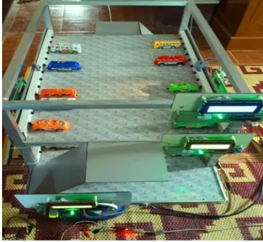
Fig-7: Show the conditions of cars in each floor
In this figure 7, there are thirteen slots in each row. In row 1 of second floor, five slots are parked which are slot 1,3,4,8 and 10. Five slots (slot 2,5,9.12 and 13) are also parked in row 2 of second floor. In first floor, eight slots are vacant in row 2 which are slot 3,4,5,8,10,11,12 and 13.
Fig-8: Show the status of parking slots on 1st floor LCD
Display
Fig-9: Show the status of parking slots in 2nd floor LCD
Display
In figure 8 and 9, parking information of each floor are displayed at the respective floor LCD display board. In Display board, ‘1’ means parked and ‘0’ means vacant.
Fig-10: Update parking information of both floors on LCD at the entrance
In figure 10, parking information of both floor are updated at the entrance LCD Display. In LCD display, slots information is displayed as available parking slots, parked slots and vacant slots. In this way, we can know overall parking information at the entrance easily.
Fig-11: Prototype of smart parking system
70
V. CONCLUSION
In this SPARK system, PIC is used in the control of the prototype of the parking management system. IR sensors are used in sensing vehicle is parked or vacant and LCDs are used for displaying available parking spaces in the proposed system. Simulation Result for each controller has been run step by step. Based on this simulation results, circuit tests have been done. I have tested circuits many times for not having errors and for giving parking information to the drivers .The prototype of parking management system using PIC and IR sensors has been successfully designed and implemented.
VI. FUTURE SCOPE
Parking information from the main controller will be sent to the PC and these parking data will be updated on the parking webpage. Drivers can know the available parking spaces via android phone application within the wifi range of that building. Finally, drivers can easily know available parking spaces without time wasting and save fuel for finding vacant space in crowed parking garage.
ACKNOWLEDGEMENTS
The author would like to express special thanks to her supervisor, Dr. Chaw Myat Nwe, Associate Professor , Mandalay Technological University for her valuable suggestion, supervision, encouragement and sharing her experience to write this research. And also, the author is also thankful to all of her teachers from Department of Electronic Engineering, Mandalay Technological University. Last, the author want to acknowledge the many colleagues at Mandalay Technological University who have contributed to the development of this journal.
REFERENCES
[1] Waqas Ahmed, Mugammad Fayaz Khan, ‘Windows
Phone App Based Real Time Tracking of Smart Parking System’, International Journal of Engineering Research and General Science, volume 3, Issue 6, November-December, 2015.
[2] Sushil Patil Devinder Singh, ‘Design and
implementation of Parking System Using Zigbee’, International Journal of Engineering Research and Technology, volume 3, Issue 4, April 2014.
[3] M.S. Karunarathne, L.D.J.F.Nanayakkara, ‘Prototype to Identify Availability of a Car in a Smart Car Park with aid of Programmable chip and Infrared Sensors, Journal of Emerging Trends in Computing and Information Sciences, volume 5, No.2 February 2014.
[4] Krishna Gopal Agrawal, Shrey Sadhani, Roshi Ahuja ,
Shubham Khandelwal, Sheetal Koul, ‘Parking
Navigation and Payment System using IR Sensors and RFID Technology’, International Journal of Computer Applications, volume 111-No 15, February 2015.