Design And Implementation Of Bank Locker
Security System Based On Fingerprint Sensing
Circuit And RFID Reader
Khaing Mar Htwe, Zaw Min Min Htun, Hla Myo TunAbstract: The main goal of this system is to design a locker security system using RFID and Fingerprint. In this system, only authenticated person can open the door. A security system is implemented containing door locking system using passive type of RFID which can activate, authenticate, and validate the user and unlock the door in real time for secure access. The advantage of using passive RFID is that it functions without a battery and passive tags are lighter and are less expensive than the active tags. This system consists of fingerprint reader, microcontroller, RFID reader, and PC. The RFID reader reads the id number from passive. The fingerprint sensor will check incoming image with enrolled data and it will send confirming signal for C# program. If both RFID check and fingerprint image confirmation are matched, the microcontroller will drive door motor according to sensors at door edges. This system is more secure than other systems because two codes protection method used.
Keywords: RFID reader, Fingerprint Sensor, PIC Micro controller, DC Motor, LCD display
————————————————————
1.
INTRODUCTION
IN this present age, safety has become an essential issue for most of the people especially in the urban areas. Some people will try to steal the property which may endanger the safety of money in the bank, house and office. To overcome the security threat, most people must install bunch of locks or alarm system. There are many types of alarm system available in the market which utilizes different types of sensors. The sensor system may not be good for all the time because it can detect different types of changes in the surrounding and the changes will be processed to be given out alert according to the pre-set value. Therefore, the security system in the bank locker by using fingerprint and RFID will be designed in this thesis. The system will provide more security than other systems because of using radio frequency identification (RFID) system, and fingerprint. The RFID based access – control system allows only authorized persons to open the locker with RFID and Fingerprint. Basically, an RFID system consists of an antenna or coil, a transceiver (with decoder) and a transponder (RF tag) electronically programmed with unique information. There are many different types of RFID systems in the market. These are categorized on the basis of their frequency ranges. Some of the most commonly used RFID kits are low frequency (30-500 kHz), mid frequency (900 kHz-1500MHz) and high frequency (2.4-2.5GHz). In the security system, the passive tag and Fingerprint are also used to be more secure. The passive tags are lighter and less expensive than the active tags. In this system only authentic person can be recovered money from bank locker with these two codes protection method.
PIC16F887
Door Motor
Relay PC
RFID reader
RFID tag Fingerprint
USB RS232
Edge detection
sensor
Fig.1- Bank Locker Security System Based on RFID and
Fingerprint
The block diagram of Bank locker system based on RFID, and fingerprint is shown in the figure. It comprises personal computer PC, RFID reader, RFID tag, PIC Microcontroller, and relay driver.
2.
P
ROPOSEDS
YSTEMD
ESIGNThe hardware configuration of the control system isbasically the combination of RFID reader, fingerprint sensor, a DC motor, a relay driver circuit and a microcontroller (PIC16F887A). The complete circuit diagram of project can be divided in three different sections:
RFID reader Fingerprint sensor
PIC16F887A Microcontroller
_________________
Khaing Mar Htwe, Zaw Min Min Htun and Hla Myo Tun
7 RE3
RB0 RB1
Start End Stop End R1
10k
R2 10k
V
B
B
V
D
D
V
E
E
RS RWE D0 D1 D2 D3 D4 D5 D6D7 1 2 34 5 6 789 10 1112 1314
RC0 RC1 RC2 RC3 RC4 RC5
RD0 RD1
12V DC 12V DC 220V DC
220V DC
Q1 C945
Q2 C945 R3
R4
1k
1k
RL2(C1) RL2(NO)
RL1(C1) RL1(NO)
DC Motor
D1
D2 RL1 12V
RL2 12V
LCD LM016L PC
RFID
Fingerprint RX
RX TX
TX
Fig.2- Overall circuit diagram of the system
Fig. 2 shows the complete circuit diagram of the project where we used the PIC16F887A, RFID reader, Fingerprint sensor, motor driver circuit, relay driver, one LCD and other peripheral circuit components. Here the PIC is used to drive the motor depending on the input data from PC and display the message of the system on LCD.
2.1 RFID
RFID stands for Radio Frequency Identification and is a term that describes a system of identification.RFID technology depends on the communication between the RFID tags and RFID readers. The range of the reader is dependent upon its operational frequency.
1. RFID reader
RFID reader works as a central place for the RFID system. In this system, CR10E RFID reader is used. It reads tags data through the RFID antennas at a certain frequency. Basically, the reader is an electronic apparatus which produce and accept a radio signals. The antennas contains an attached reader, the reader translates the tags radio signals through antenna, depending on the tags capacity. RFID reader receives RF transmissions from an RFID device and transmits to a host system for processing. The reader is a device that has one or more antennas that emit radio waves and receive signals back from the tag. The specification of the CR10E RFID reader is;
Frequency : 125 kHz
Read Range : Up to 10 cm / Up to 5 cm Communication : USB Host
Operating temperature : -10˚C to +70˚C Power : 5VDC
Features : Audible Buzzer, LED Green and Red
2. RFID passive tag
A passive RFID tag has without a battery. Tags contain microchips that store the unique identification (ID) of each object. The ID is a serial number stored in the RFID memory. RFID tags can be different sizes and shapes depending on the application and the environment at which it will be used. When radio waves from the reader reach the chip’s antenna, it creates a magnetic field. The tag draws power from the field and is able to send back information stored on the chip. Passive tag collect’s hundreds of tags within 3 meters from a single reader and then it collects 20 tags moving at 3 mph or slower.
3. Tag Standard
Readers use near and far fields of methodology to communicate to the tag through its antennas. If a tag wants to respond to the reader then the tag will need to receive energy and communicate with a reader. For example, passive tags use either one of the two following methods. Near Fields: Near field uses method similar to transformer, and employs inductive coupling of the tag to the magnetic field circulating around the reader antenna.
Fig. RFID near field methodology
Far Field: Far field uses method similar to radar, backscatter reflection by coupling with the electric field.
Fig. RFID far field methodology
systems with far fields usually use longer read range UHF (Ultra high frequency) and microwave.
1. Adafruit Optical Fingerprint Sensor
Fig- Adafruit optical fingerprint sensor
Fingerprint
Vcc
2
3 Vcc
RX TX
Arduino PIC
Vcc
TX
RX
GND Vcc
RX
TX
GND
Fig- Circuit diagram of the adafruit optical fingerprint sensor
Fingerprints are patterns of ridges and valleys on the surface of the finger. Like everything in the human body, these ridges form through a combination of genetic and environmental factors. The genetic code in DNA gives general orders on the way skin should form in a developing fetus, but the specific way it forms is a result of random events. The optical fingerprint sensor will make adding fingerprint detection and verification super simple. These modules are typically used in safes -there's a high powered DSP chip that does the image rendering, calculation, feature-finding and searching. Connect to any microcontroller or system with TTL serial, and packets of data to take photos, detect prints, hash and search.This fingerprint sensor can also enroll new fingers directly up to 120 fingers can be stored on the onboard FLASH memory.The fingerprint is really easy to use with the serial UART. There are basically two requirements for using the optical fingerprint sensor. Firstly, fingerprint will be needed to enroll-that means assigning ID #'s to each print. The pin#2 and pin#3 from the Arduino is connecting to green and white wires of the fingerprint sensor. Then the supply voltage (5V) of the Arduino is also connecting to the supply system of the sensor. When verifying and uploading the program, the fingerprint sensor is finding in serial monitor of the tool box. If the fingerprint sensor started, the identification (ID) number would be typed. The user finger is pressing the three times. The first two times is converting the finger image and removing this finger. The last time of the finger image is storing this finger. And then, the fingerprint sensor can easily 'search' the finger, asking it to identify which ID (if any) is currently being photographed.
2.3 PIC16F887A Microcontroller
Fig-PIC16F887A Microcontroller
PIC16F887 is one of the latest products from Microchip. It features all the components which modern microcontrollers normally have. For its low price, wide range of application, high quality and easy availability, it is an ideal solution in application such as: the control of different processes in industry, machine control devices, measurement of different values etc. PIC microcontroller has range of low end 8 bit microcontrollers and smallest have only 8 pins, largest 40 pins.PIC16F887Amicrocontroller have 40 I/O pins. It supports 35 bi-directional I/O pins and 8K bytes of storage memory for programming. PIC16F887A have 5 I/O ports such as Port A, B, C, D and E. It operatingfrequency DC is 20MHz and it uses as a main control unit to control of the whole system.
3.
S
OFTWAREI
MPLEMENTATIONTo implement the actual algorithm in the PIC16F887A the MikroC Pro compiler is used. For the RFID reader, C# language is used. The arduino software is used in the fingerprint sensor.
Initialize Fingerprint USBHID RFID USB serial 1 Motor Control UART USB serial 2
Read serial data for fingerprint USBHID
Read serial data for RFID USB serial 1
Closed?
Start
End
No
No
Yes
Display “Try again” Serial number
valid
Yes
Serial data UART USB serial 2 to
open gate
9 Start
UART Initial gate sequence==0
“a” read to PIC
gs==1
Gate opened gs==2
If gs==2 && gate fully opened
Motor stop Delay 10sec Motor Closed
gs==3
If gs==3 && gate closed
Motor stop
gs==0
Exit?
End
Yes No
Yes No
No
Yes
No
Yes
No
Yes
Display Opened
Display Closing
Display Closed If gs==1 &&
gate closed
Display Opening
Send back closed confirmation
Fig.4- Flowchart for the PIC program
4.
TEST
AND
R
ESULTSOF
THE
SYSTEM
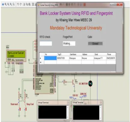
The RFID reader reads the code 10 digits from RFID tag and sends to the PIC. The fingerprint sensor will check incoming image with enrolled data and it willsend confirming signal to PIC. If both RFID check and fingerprint image confirmation are matched, the microcontroller will drive door motor according to sensors at door edges. If the receive RFID and fingerprint codes will send to the
microcontroller to open the bank locker. USB connection is used as a carrier to connect the PC and the microcontroller.
Fig.5- Proteus Simulation of the door motor is opening with
RFID reader and fingerprint
Fig. 6- Proteus Simulation of the door motor is closing with
RFID reader and fingerprint
Fig.7- Complete Circuit Construction of Door Motor Control
Fig.8- Prototype Overview for the Door Motor Control System
5.
CONCLUSION
In this study, a security system is proposed by using passive RFID and Fingerprint. It is a low cost, low in power conception, compact in size and standalone system. The microcontroller compares the two passwords entered by PC. If these passwords are correct, the microcontroller provides necessary control signal to open the bank locker otherwise the door remains locked. The proposed system can be used in other places such as office and library. Future work of this system can be improved by applying the security system based on GSM and password for better security of the person.
A
CKNOWLEDGMENTThe author would like to thank to Dr. Hla Myo Tun, Associate Professor and Head of the Department of Electronic Engineering, Mandalay Technological University for his help.
REFERENCES
[1] ―A Digital Security System with Door Lock System Using RFID Technology‖, Gyanendra K Verma, Pawan Tripathi, 2010.
[2] ―Locker Security System Using RFID And GSM Technology‖, Aruna.D.Mane1
and Sirkazi Mohd Arif2, 2013.
[3] ―RFID Based Embedded System for Vehicle Tracking and Prevention of Road Accidents‖, Kumar Chaturvedula .U.P, 2012.
[4] ―A Survey Paper on Radio Frequency IDentification (RFID)Trends‖,2013, Christoph Jechlitschek, [email protected]
[5] IET. 2009. Radio Frequency Identification Device Technology (RFID), The Institution ofEngineering
and Technology, Available at: