Initial Alignment for SINS based on Low-cost
IMU
Yi Jiong
Chinese Academy of Sciences / Shanghai Institute of Technical Physics, Shanghai, China Email: [email protected]
Zhang Lei and Shu Rong and Wang Jianyu
Chinese Academy of Sciences / Shanghai Institute of Technical Physics, Shanghai, China Email: { leizhang, shurong, jywang }@ mail.sitp.ac.cn
Abstract—The initial alignment is vital to the strapdown
inertial navigation system (SINS). In this work, an efficient initial alignment method for SINS based on a six-degree of freedom inertial measurements unit (IMU) is proposed. The three dimensional linear accelerations and angular rates are acquired from a data acquisition board which contains a low-cost IMU. Preprocess the gyro data and modeling the SINS error model for initial alignment. Analysis the observability of this SINS error model and then simplify the model based on the observability. A kalman filter is conducted to estimate the misalignment angle. The results show that the initial alignment method proposed in this paper is advisable for a SINS based on low-cost IMU on a stationary base.
Index Terms—SINS; Initial Alignment; Kalman Filter;
Obervability; Data Acquisition
I. INTRODUCTION
Since the 1950s, the strap-down inertial navigation system (SINS) has been widely used in many fields such as positioning and navigation of ships, aeroplanes, vehicles, and missiles etc. The initial misalignment is one of the major error sources of SINS. Considering the initial alignment errors will affect the system error in the position, velocity and attitude (PVA), the SINS must be preferable aligned before positioning and navigation.
The aim of initial alignment of SINS is to get a coordinate transformation matrix from body frame to navigation frame and conduct the misalignment angles to zero or as small as possible. In a broad sense, initial alignment of SINS can be divided into two categories i.e. stationary based and moving based alignment. SINSs are entirely self-contained, by using the measurements of the local gravity and Earth rate [1]. Theoretically, an analytic self-alignment method for strapdown inertial navigation system is functionally equal to the physical gyrocompassing in gimbaled systems. The error characteristics of both systems seem to be identical at steady state in a stationary base [1]. Generally, alignment of SINS can be divide into two phases i.e. the coarse and the fine alignment. The purpose of coarse alignment is to estimate the orientation of the instrumental axis relative to navigation frame. The purpose of fine alignment is to
compute the small misalignment angles between reference frame and the body frame accurately through processing the information of various sensors data [2].
The requirements of initial alignment of SINS are high accuracy and short time. There are many complications that make alignment both time consuming and complex. Accurate alignment is crucial, however, this is based on alignment over long periods of time. A compromise of accuracy and time consumption of initial alignment should be made.
This paper proposes initial alignment for SINS based on low-cost IMU on a stationary base. First, acquire linear accelerations and angular rates from IMU, then denoise the gyro data. Next, modeling the initial alignment model and analysis the observability of alignment, simplify the alignment model based on the observability. Subsequently, a kalman filter was conducted to estimate the misalignment angle. Finally, the test results are presented to show performance of the proposed initial alignment for SINS based on low-cost IMU on a stationary base.
II. SINSARCHITECTURE
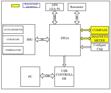
Generally, a strapdown system is a major hardware simplification of the navigation system. The accelerometers and gyros are mounted in body coordinates and are not mechanically moved. Instead, a software solution is used to keep track of the orientation of the IMU and rotate the measurements from the body frame to the navigational frame. This method overcomes the problems encountered with the navigation system, and most importantly reduces the size, cost, power consumption, and complexity of the system. This section will give a brief overview of the SINS architecture, which is shown in Fig. 1.
FPGA Barometer GPS
LEA-5S
IMU
Configure Chip MAGNETO
METER
SPI
UA
R
T
SP
I
Reserved model and interface
COMPASS
USB CONTROLL
ER
USB
PC
ACCELEROMETER
GYROSCOPE
TEMPERATURE
Figure 1. Architecture of SINS.
shown in the architecture is for the GPS/SINS/BARO integrated navigation system [3]. Besides, the compass and magnetometer interfaces are reserved for future developments. The data of GPS, barometer, and IMU are sent to FPGA, then packed and acquired by PC via USB controller. The data are processed in PC.
III. ALGORITHM OF INITIAL ALIGNMENT In this article the initial alignment have three stages, that is, the data preprocess, the coarse and fine alignment. In the data preprocess stage, the null bias of gyro is stripped almost and the random walk of gyro is minimized. In the coarse alignment stage, a fairly good initial condition for the fine alignment is provided and it can made the total alignment time shorter. In the fine alignment stage, the small misalignment angles between references frame and the body frame are computed accurately.
A. Data Preprocess
The error model of gyro can be depicted as:
b g
ε
=
ε
+
ε
(1)Where,
ε
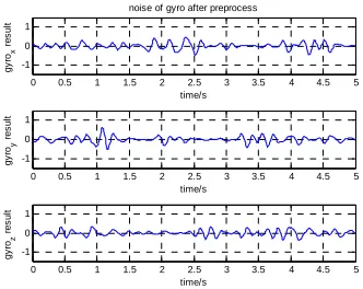
b is null bias, εg is the random walk whichregarded as white noise. Null bias of gyro is a slowly changing signal, it can be regarded as a constant on every start. We can strip it from the outputs of gyro in mean filter. After the null bias is stripped, minimize the random walk of gyro effectively is very important to improve the accuracy of the output of gyroscope. Considering the random walk of gyro is weakly nonlinear, unsmooth and effected by the uncertain factors easily, the wavelet threshold filter is very effective to denoise the random walk. In this work, we choose the 5 scales db4 wavelet to improve the gyro’s data.
B. Coarse Alignment
The purpose of coarse alignment is to provide a fairly good initial condition for the fine alignment. This can made the total alignment time shorter. Generally, the coarse alignment method can be divided into analytic coarse alignment and optical alignment. Here, the analytic coarse alignment method is adopted. The
accelerometers and gyros measure the gravity vector and Earth rate vector related to body frame, respectively. These two vectors are known constant in navigation frame, assume that the navigation axes are aligned with the local-level north, east, and down. Then the gravity and Earth rate vectors can be expressed as:
[0
0
]
n T
g
=
−
g
(2)[
cos
0
sin ]
n
ie ie
L
ieL
ω
=
ω
−
ω
(3)The transformation of gravity vector and Earth rate vector from body frame to navigation frame are respectively depicted below:
g
n=
C g
bn b (4)n n b ie
C
b ieω
=
ω
(5) Where,C
bn is the transformation matrix. Definev
= ×
g
ω
ie, the transformation matrix can be depicted as:1
(
)
(
)
(
)
( )
(
)
(
)
n T b T
n n T b T
b
n n T b b T
g
g
C
v
v
v
g
v
g
−
⎡
⎤ ⎡
⎤
⎢
⎥ ⎢
⎥
= ⎢
⎥ ⎢
⎥
⎢
×
⎥ ⎢
×
⎥
⎣
⎦ ⎣
⎦
(6)
The relationship between strapdown navigation frame and real reference frame can be depicted in three misalignment angles
φ
N,φ
E andφ
D. Analysis the errorof the coarse alignment, the misalignment angles can be derived [4] :
E
N D D
E E
/
(
)/ 2
sec / 2
/
sec /
N
E ie
D ie
f
g
f
tgL f
g
L
f tgL g
L
φ δ
φ
δ
δ
δω
ω
φ
δ
δω
ω
=
⎧
⎪ = − +
−
⎨
⎪
=−
+
⎩
(7)
It is observed from above formulation that not only the north specific force but also the vertical force and azimuth gyro uncertainties will induce the east level error. This situation is quite different from that occurred in a gimbaled system [1].
C. Fine Alignment
Fine alignment is a precise alignment stage in which the small misalignment angles between references frame and the body frame are computed accurately through processing the information of various sensors. In this section, a model for initial alignment is depicted and the kalman filter for fast alignment is presented.
a. Model of Initial Alignment
should be derived. It is well known that the description of the SINS error propagation using a linearized error model is quite a good approximation. The characteristics of SINS can be derived from the linear error model. The SINS error model plays an important role in implementing a Kalman filter for alignment. The model of SINS initial alignment is formed in the NED geographic frame, which is denoted n. The computational navigation frame is denoted n'. The carrier body frame is denoted b, and its three axes parallel the three axes of carrier, thepositive directionis Forward- Right-Down.
The state equation of initial alignment is:
X
&
=
FX
+
GW
(8) WhereX
,F
, G,W
serve as system states, transfer matrix, noise matrix and system noise vector of the system, respectively. Therein, G is a 8×8 unit matrix. Ignoring the position and velocity errors, the state of initial alignment can be written:[
]
TN E D N E D N E
X
=
φ φ φ ε ε ε
∇ ∇
(9)Where the subscripts N, E and D denote the north, east and down of geographical frame.
φ
N ,φ
E,φ
D are the attitude errors;ε
N ,ε
E ,ε
D and∇
N ,∇
E are the constant error of gyros and accelerometers, respectively. The derivatives of them are zero. So, the state transportation matrix and system noise vector can be depicted as:3 2
5 8
0 sin 0 1 0 0
sin 0 cos 0 1 0 0
0 cos 0 0 0 1
0
ie
ie ie
ie
L
L L
F
L
ω
ω
ω
ω
×
×
− −
⎡ ⎤
⎢ − ⎥
⎢ ⎥
=⎢ − − ⎥
⎢ ⎥
⎢ ⎥
⎣ ⎦
(10)
1 5
[
gn ge gd0
]
TW
=
ω
ω
ω
× (11)Considering the coupling of vertical specific force and level misalignment angle is very weak, the measurement of vertical specific force can be ignored, so we can take the level specific force as measurement signal. The measurement equation of initial alignment is:
Z
=
HX
+
V
(12)[
]
T N EZ
=
f
f
(13)V
is the measurement noise, it can be depicted as:[
]
T aN aEV
=
v
v
(14)H
is the measurement matrix, it can be depicted as:2 6
0
0
0
g
H
g
×
⎡
⎤
⎢
⎥
= ⎢
⎥
⎢
−
⎥
⎣
⎦
(15)
b. Observability analysis
The estimation result of the system state is a good performance index for the degree of observability of the
states of the initial alignment. If the estimation of a state by Kalman filter is convergent, the state will be observable. If the estimation of a state is not convergent, the state will be unobservable. The faster the convergent rate is, the higher the degree of observability of the state is [5].
Consider a linear time-invariant system. If the rank of the observability test matrix is equal to the order of the system, then the system is completely observable. On the contrary, if the system is not completely observable, the number of unobservable states is the difference between the order of the system and the rank of the observability test matrix [4].
For the reason that some states can not be estimated have effects on estimating the azimuth misalignment, the azimuth misalignment can not be estimated as well as the leveling misalignment. A rank test of observability matrix can determine whether the system is completely observable or not. The observability matrix can be written as:
2 7
[
...
]
TO
=
F
FH
FH
FH
(16)( )
5
rank O
=
, the number of unobservable states is the difference between the order of system and the rand of the observability matrix. So, the system is not completely observable, there are only 5 observable states and left 3 unobservable states. It is necessary that the misalignment angles be all observable. The combination of three unobservable states could be∇ ∇
N,
E,
ε
E or∇
E,
ε ε
E,
D. The faster the convergence rate is, the higher the degree of observability of the state is. According to the analysis, the most reasonable choice of the three unobservable states are∇ ∇
N,
E,
ε
E for the initial alignment process [6]. Once the unobservable states have been selected, the improved estimation algorithm for computing the estimates of misalignment angles should be designed. The fast convergence ofφ
D requires higher degree ofobservability of
φ
D, but the degree of observability of itcan’t be increased because of the limitation of
ε
E . Thecharacteristic of SINS determines that
ε
E isunobservable as analyzed above. The estimate of the
φ
Dcan be depicted as:
(
sin
) / (
cos )
D E ie
L
N ieL
φ
∧=
φ
∧&−
ω
φ
∧ω
(17)Equation 17 shows that the azimuth error can be computed directly from the estimates of the leveling error about the north axis and the leveling error rate about the
east axis. Therefore, the convergence rate of
φ
D∧
, , ,
k k k k
F H Q R
0, 0
X P
∧
− −
1
( )
T T k k k k k k k
K =P H− H P H− +R −
1 1
1
k k k k T k kk k k
X F X Gu P F P F Q
∧ ∧
−
− −
− −
= +
= +
( )
( )
k k k k k k k k k k
X X K z H X P I K H P
∧ ∧
∧
− −
−
= + −
= − Model parameters
Initial estimate
Prediction
Kalman gain
Mesurement update
k
z
mesurementFigure 2. The Structure of Discrete Kalman Filter
Figure 3. Data Acquisition Board
system won’t used at Earth pole, we can neglect this effect.
D. Kalman filter for fast alignment
According to the analytic result of observability, the constant null drift of accelerometers and constant drift of east gyro can be ignored. In terms of the error model and the observation of SINS, the discrete Kalman Filtering equations are formulated as follows:
1 1
1
1
( )
( )
( )
k k k k T k k k k k
T T
k k k k k k k
k k k k k k k k k k
X F X Gu
P F P F Q
K P H H P H R
X X K z H X
P I K H P
∧ ∧
−
− −
−
−
− − −
∧ ∧
∧
− −
−
⎧ = +
⎪
⎪ = +
⎪
= +
⎨ ⎪
⎪ = + −
⎪
= − ⎩
(18)
The simplified system state vector of initial
alignment is depicted below.
[
N E D N D]
TX
=
φ
φ
φ
ε
ε
(19)1 5
0
sin
0
1 0
sin
0
cos
0
0
0
cos
0
0
0
0
ie
ie ie
ie
L
L
L
F
L
ω
ω
ω
ω
×
−
−
⎡
⎤
⎢
⎥
⎢
⎥
=
⎢
−
⎥
⎢
⎥
⎣
⎦
(20)
The process of kalman filter is depicted in Fig. 2.
F
k is the discrete system state transformation matrix.H
k is the discrete measurement matrix.Assumption that the initial misalignment angels of north, east and down are about
5
° ,5
° and50
° , respectively. The constant drifts and angular randomwalk of each gyro are
0.015 /
°s
and4.2 /
°h
, respectively. The constant drifts and velocity random walk of each accelerometer are700
µ
g
and300
µ
g
, the latitude is about31.28
°.IV. APPLICATIONTESTANDALIGNMENT RESULT
The data acquisition board which is shown in Fig.3 is applied to a GPS/SINS/BARO integrated system [3]. The GPS applied to this system is a GPS module Ublox LEA-5S, this module provides excellent performance and flexibility at an economical price. A 32-channel acquisition engine with over 1 million effective correlators is capable of massive parallel searches. This enables a Time To First Fix (TTFF) less than 1 second. The barometer is VTI’s SCP1000-D01 pressure sensor, it detects the smallest barometric pressure changes, enabling easy local altitude measurements. It communicates over standard SPI interface and the resolution is 2 Pa. The altitude measurement based on pressure is a relative measurement it compares pressures at different places. The altitude H as a function of pressure P is obtained from (21) below.
0.19
44.33
*[1 ( /101325
)
]
BARO
H
=
km
−
P
Pa
(21)IMU give angular rates and linear accelerations for the inertial navigation. The SINS can utilize either and off-the-shelf ring laser gyroscope (RLG) IMU or MEMS IMU. Considering the performance-price ratio, a low cost MEMS based tri-axis inertial sensor is applied. This IMU is a complete triple axis gyroscope and triple axis accelerometer inertial sensing system which is precision-aligned across axes, and is calibrated for offset and sensitivity. The data of GPS, BAROMETER, and IMU are sent to FPGA and packed in it. Then send the packages to PC via a USB microcontroller. The specification of the IMU is presented in table 1.
0 100 200 300 400 500 600 700 800 900 1000 0
0.5 1
δφE
/
a
rc
m
in
0 100 200 300 400 500 600 700 800 900 1000 -0.6
-0.4 -0.2
δφN
/ a
rc
m
in
0 100 200 300 400 500 600 700 800 900 1000 -150
-100 -50 0
δφU
/ a
rc
mi
n
t / s
Figure 7. Error estimation of misalignment angle.
0 0.5 1 1.5 2 2.5 3 3.5 4 4.5 5 -1
0 1
time/s
no
is
e o
f
g
y
rox
noise of gyro
0 0.5 1 1.5 2 2.5 3 3.5 4 4.5 5 -1
0 1
time/s
noi
s
e
of
gy
roy
0 0.5 1 1.5 2 2.5 3 3.5 4 4.5 5 -1
0 1
time/s
no
is
e o
f
g
y
roz
Figure 4. Noise of gyro
0 0.5 1 1.5 2 2.5 3 3.5 4 4.5 5 -1
0 1
time/s
gy
rox
a
fte
r
fi
lte
r noise of gyro after filter
0 0.5 1 1.5 2 2.5 3 3.5 4 4.5 5 -1
0 1
time/s
gy
roy
af
ter
f
ilt
er
0 0.5 1 1.5 2 2.5 3 3.5 4 4.5 5 -1
0 1
time/s
gy
roz
a
fte
r
fi
lte
r
Figure 5. Noise of gyro after filter
0 0.5 1 1.5 2 2.5 3 3.5 4 4.5 5 -1
0 1
noise of gyro after preprocess
time/s
gy
rox
re
s
u
lt
0 0.5 1 1.5 2 2.5 3 3.5 4 4.5 5 -1
0 1
time/s
gy
roy
re
s
u
lt
0 0.5 1 1.5 2 2.5 3 3.5 4 4.5 5 -1
0 1
time/s
gy
roz
re
s
u
lt
Figure 6. Noise of gyro after wavelet denoise
azimuth misalignment angle
φ
D is about 100s. This initial alignment method for SINS that is proposed here can reduce the time of initial alignment greatly, it is verified to be quite effective.V. CONCLUSION
In this paper, initial alignment for SINS based on low-cost IMU on a stationary base is proposed. The hardware is designed to acquire the outputs of gyros and accelerometers, meantime, the GPS data is also acquired. The acquired gyro data are preprocessed to denoise the null bias and random walk. The simplified system states are obtained based on the analysis of the obervability of system states. To shorten the convergent time, the simplified kalman filter for initial alignment is adopted. The test result show that the initial alignment method proposed in this paper is superior to the traditional method and it is advisable for a SINS based on low-cost IMU on a stationary base.
ACKNOWLEDGMENT
This paper is supported by Open Research Fund of State key Laboratory of Information Engineering in Survering, Mapping and Remote Sensing (No.09P01) and Open Research Fund of LGISEM (No.LGISEM0811).
TABLE I. SPECIFICATION OF IMU
Parameter Conditions Value Unit
Gyro
sensitivity
2 5°,±3 0 0 /° s .07326 °/s /L S B
2 5°, 1 5 0 /± ° s .03663 °/s /L S B
2 5°,±7 5°/s .01832 °/s /L S B
Bias In Run
2 5 , 1° σ .015 °/s
Radom walk
2 5° 4.2 °/r t h r
Noise
2 5°,±3 0 0 /° s,
2-tap filter
0.60 °/s r m s
2 5°,±1 5 0°/s,
8-tap filter
0.35 °/s r m s
2 5°,±7 5°/s, 32-tap filter
0.17 °/s r m s
Accel
sensitivity 2 5° 2.522 m g /L S B Bias In
Run
2 5 , 1° σ 0.7 mg
Radom walk
REFERENCES
[1] YEON FUH JIANG, Error Analysis of Analytic Coarse
Alignment Methods, IEEE TRANSACTIONS ON AEROSPACE AND ELECTRONIC SYSTEMS, VOL.34, NO.1 JANUARY 1998.
[2] Zhang Tianguang, Wang Xiuping, Strapdown Inertial
Navigation Technology, National Defense Industry Press.
[3] Yi jiong, Zhang lei, GPS/SINS/BARO Integrated
Navigation System for UAV, IFITA 2010 Proceedings, VOL.3, 19-25.
[4] Britting,K.R, Inertial Navigation System Analysis. New
York: Wiley Interscience, 1971, ch.9.
[5] YEON FUH JIANG, YU PING LIN, Error Estimation of
INS Ground Alignment Through Observability Analysis, IEEE TRANSACTIONS ON AEROSPACE AND ELECTRONIC SYSTEMS, VOL.28, NO.1 JANUARY 1992.
[6] JIANG CHENG FANG, DE JUN WAN, A Fast Initial
Alignment Method For Strapdown Inertial Navigation System on Stationary Base, IEEE TRANSACTIONS ON AEROSPACE AND ELECTRONIC SYSTEMS, VOL.32, NO.4 OCTOBER 1996.
[7] Zhang Chuanbin, Tian Weifeng, Jin Zhihua, A Novel
Method Improving the Alignment Accuracy of A Strapdown Inertial Navigation System on A Stationary Base, MEASUREMENT SCIENCE AND TECHNOLOGY, 15(2004) 765-769.
[8] YAN Gong-min, QIN Yong-yuan, Initial Alignment
Accuracy Analysis and Simulation of Strapdown Inertial Navigation System on a Stationary Base, Computer Simulation, VOL.23, NO.10 OCTOBER 2006.
[9] Xionlong Wang, Gongxun SHEN, A fast and accurate
initial alignment method for strapdown inertial navigation system on stationary base, Journal of Control Theory and Applications 2(2005) 145-149.