Comparison of Power Transfer Characteristics
between CPT and IPT System and Mutual
Inductance Optimization for IPT System
Chenyang Xia
School of Information and Electrical Engineering, China University of Mining and Technology, Xuzhou, China Email: [email protected]
Yuejin Zhou, Juan Zhang and Chaowei Li
School of Environment Science and Spatial Informatics, China University of Mining and Technology, Xuzhou, China Jiangsu Provincial Xuzhou Pharmaceutical Vocational College, Xuzhou, China
Puyang Power Supply Company, Puyang, China Email: {yuejinzh, xwen80, chaowei-lee }@163.com
Abstract—The capacitive power transfer (CPT) system and inductively power transfer (IPT) system are the two typical wireless power transfer systems. Based on the power transfer characteristics, the power transfer capacity of the two wireless power transfer systems were analyzed. Firstly, the maximum power transfer capacity and its existing condition of the two wireless power transfer systems were analyzed, and the choose gist of wireless power transfer system was presented according to the analysis result; then, the mutual inductance of 4 typical IPT systems was optimized for achieving maximum power transfer; finally, the theoretical research was justified via a simulation and experiment.
Index Terms—capacitive power transfer (CPT), inductively power transfer (IPT); mutual inductance; optimization.
I. INTRODUCTION
After nearly 20 years of development, the wireless power transfer (WPT) technology has got great research and application in related fields [1-6]。According to the difference of principle for wireless power transfer, the WPT technology generally can be divided into three types, such as inductively power transfer (IPT) based on the principle of electromagnetic induction [7-9], capacitive power transfer (CPT) based on the principle of capacitive wireless electric power transmission [10-11], coupled magnetic resonances power transfer (CMRPT) based on the principle of electromagnetic coupling resonance energy transfer technology [12-13]. After years of research, the IPT technology has got considerable achievements; and due to the CMRPT technology can realize high power wireless transmission beyond a few meters or even tens of meters, it has currently received many attention; while for the capacitive coupled wireless power transfer technology, analysis and research are still in its infancy, the main study is still reflected in the stability and function of the realization, and the study for its power transmission characteristic is not enough.
At present, in some system need to adopt WPT technology, it mostly uses IPT technology, but the IPT system needs a high frequency to generate a magnetic field, typically 10k-10MHz, which will cause a big electromagnetic interference; and the coupling magnetic field which the technology relied on can be easily shielded by some metal conductor with small resistance rate, and larger eddy current losses can also be produced, therefore, the IPT technology based on magnetic coupling applied in a metal environment is greatly limited.
In contrast, there are certain advantages of the electric field coupling; the CPT technology can overcome the disadvantage that the magnetic energy can’t transmit in the metal shielding environment. The CPT technology can not only transmit through the metal body, reduce energy loss, but also has good anti-interference ability of the magnetic field. Strong anti-interference makes the device can work in saturated or intense magnetic fields environment, and can reduce energy loss and electromagnetic interference. Therefore, the CPT technology has a number of advantages that IPT technology unparalleled.
From the perspective of power transfer characteristic, the paper has made a comparative analysis between the CPT and the IPT technology in the same environment. Firstly, the paper has got their maximum power transmission capacity and the establishment of conditions; at the same time, the power transmission capacity of the two structures were compared and analyzed; then the power transmission characteristics of the two structures was analyzed in the same application environment; and the wireless power transmission technology selection basis in different environments was given, finally, the mutual inductance of 4 typical IPT systems was optimized for achieving maximum power transfer.
In this section, the principle of CPT and IPT system were introduced firstly, and then, a typical CPT and IPT system topology were introduced, finally, the Coupling mechanism of CPT and IPT system were analyzed.
A: Principle of CPT and IPT System
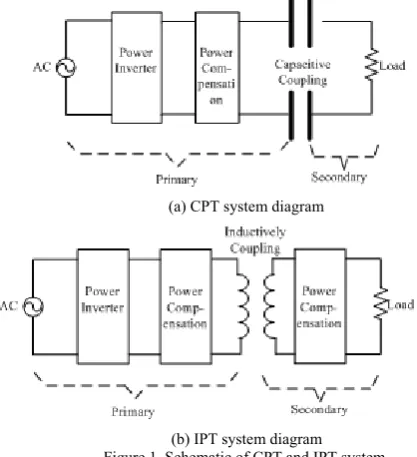
A typical CPT system and IPT system diagram are shown in Fig. 1 (a) and Fig. 1 (b) below.
In the CPT system, the input voltage AC passes through the inverter and power compensation device, then it works as the primary input voltage of the metal plate, when the secondary side of the two metal plates is close to the primary side and there is a potential difference, alternating primary electric field will produce power on the secondary metal plate, and the power will be supplied to the load.
In the IPT system, the input voltage AC passes through the inverter and power compensation device, then it works as the input voltage of the primary resonance coil, by the magnetic field coupling between two coils, the power will be supplied to the load.
(a) CPT system diagram
(b) IPT system diagram Figure 1. Schematic of CPT and IPT system
B. CPT and IPT System Topology Introduction
The typical topologies of CPT system and IPT system are shown in Fig. 2 (a) and Fig. 2 (b) below.
(a) Topology of CPT system
(b) Topology of IPT system Figure 2. Topologies of CPT and IPT
DC power Edc and S1 ~ S4 constitute part of high frequency energy inverter, by alternately turn on switches S1, S4 and S2, S3 to achieve both positive and negative energy injection. Vp is the equivalent output voltage of the inverter.
By real-time detection of the output voltage through the crossing point to achieve soft-switching inverter circuit, in theory, the inverter circuit switching loss is zero in soft-switching mode.
In the CPT system topology, Cs1,Cs2 are the equivalent capacitance of the two metal panels, Ls and capacitor Cs1,Cs2 constitute the resonant composition network, RL is the equivalent load resistance of the system; the system works through the electric field coupling between Cs1 and Cs2 to achieve wireless power transmission.
In the topology of IPT system, Lp and Cp constitute the primary resonant network, Ls, Cs constitute the secondary resonant network, Rp is the equivalent series resistance of the primary inductance Lp, M is the mutual inductance between Lp and Ls, RL is the equivalent load resistance of the system, the system works through the magnetic coupling between Lp and Ls to achieve wireless power transmission.
C. Coupling Mechanism Analysis of CPT and IPT System
The typical coupling structure of CPT system is shown in Fig. 3.
Figure 3. Coupled structure of CPT system
In Fig. 3, the coupled structure of the CPT system is composed of two iron bodies with radius r and pitch d,
the two iron are put in parallel perpendicular to axis O1O2, like such a coupling structure, the equivalent capacity of
Cs1,Cs2 is[10]
2
0 0
2 1 r r
s s
A r
C C
d d
ε ε π ε ε
= = = (1)
With Fig. 2(a), the equivalent capacitance Cs of the capacitors Cs1,Cs2 connected in series is
2
1 0
2 2
s r
s
C r
C
d
π ε ε
= = (2)
Meanwhile, the equivalent series resistance of capacitor Cs is[10]
2 2
0 0
tan tan tan
s C
s r r
d R
C r r
d
δ δ δ
ω ωπ ε ε ωπ ε ε
= = = (3)
Where, δ is the dielectric loss, ω is the angular frequency.
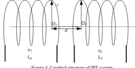
The coupling structure of a typical IPT system is shown in Fig. 4.
Figure 4. Coupled structure of IPT system
Fig. 4 shows the coupled structure of IPT system composed with two solenoids with radius r. the primary
winding coils is composed with n1 turns, while the secondary coil is composed with n2 turns, the two coils are placed in parallel perpendicular to axis O1O2, for such a coupling institution, the primary inductance Lp[14]
2
1 0
2 ln p
r
L n r
D
μ ⎛ ⎞ = ⎜ ⎟
⎝ ⎠ (4)
Similarly, the secondary inductance Ls is 2
2 0
2 ln
s
r
L n r
D
μ ⎛ ⎞
= ⎜ ⎟
⎝ ⎠ (5) The coupling coefficient k between the two coil is
approximately[14],
3
2 2 3
( )
r k
r d =
+ (6) Then, we can see that the coil mutual inductance M is
4
1 2 0
2 2 3
2 ln
( )
p s
r n n r
D M k L L
r d
μ ⎛⎜ ⎞⎟
⎝ ⎠
= =
+ (7) Where u0 is the magnetic permeability of air, r is the
coil radius; D is the diameter of winding.
III. POWER TRANSMISSION ANALYSIS AND PARAMETER OPTIMIZATION OF CPT AND IPTSYSTEM
Suppose that the voltage source inverter circuit works in the zero-voltage soft-switching mode, then, Vp is
p dc
2 2
V = π E (8)
A: Power Transmission Analysis and Optimization of CPT System
The equivalent circuit of the CPT system showed in Fig. 2 (a) is shown in Fig. 5.
Figure 5. Equivalent circuit of CPT system
It can be seen from Fig. 5, the system's natural resonant angular frequency is
0 1
s s L C
ω = (9) When the system works in the natural resonant frequency, the system output voltage is
0
s s L
p
L C L
R
V V
R R R
=
+ + (10) Then the system output power can be obtained as
(
)
2
2 0
2
s s L
CPT p
L L C L
V R
P V
R R R R
= =
+ + (11) In the real system, the impedance of the compensation inductor Ls is negligible, and then the output power of the
system is approximately
(
)
2
2 2
0
2 2
tan
s
L L
CPT p p
L C L
L s
V R R
P V V
R R R
R C
δ ω
= ≈ =
⎛ ⎞
+ +
⎜ ⎟
⎝ ⎠
(12) As can be seen from the above equation:
(A) For a particular load resistor RL, the smaller the capacitance equivalent resistance RCs, the greater the output power of the system, the maximum is
2 max1
p CPT
L V P
R
− ≈ (13) (B) For a particular frequency and coupling institution, when the capacitor equivalent resistance RCs is constant, Making
0
CPT L dP
dR = (14)
When
tan
s
L C
s
R R
C
δ ω
= = (15)
The system maximum power output is 2
0 2
2 2 2
4 4 tan 4 tan
mac s
r
p s
CPT p p
C
r
V C d
P V V
R
π ε ε ω ω
δ δ
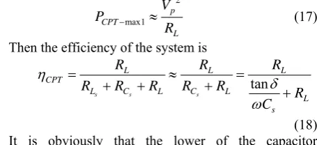
(C) For a specific system operating frequency and load resistance, the greater the capacitance Cs (field area is larger, the smaller the distance), the greater the output power of the system, the maximum is
2 max1 p CPT L V P R
− ≈ (17) Then the efficiency of the system is
tan
s s s
L L L
CPT
L C L C L
L s
R R R
R R R R R
R C η δ ω = ≈ = + + + + (18) It is obviously that the lower of the capacitor equivalent series resistance RCs, the greater the load resistor RL, the higher the efficiency of the system.
B: Power Transmission Analysis and Optimization of IPT System
The equivalent circuit of the IPT system showed in Fig. 2 (b) is shown in Fig. 6.
Figure 6. Equivalent circuit of IPT system When
0
1 1
p p s s
L C L C
ω = = (19) The system was resistive transmission.
Then, the system output power is
(
)
2 2 2
p
IPT 2 2 2
p
L s L M V R P
M R R R
ω ω = ⎡ + + ⎤ ⎣ ⎦ (20)
In the real system, the impedance of compensation inductor Ls is negligible, in the following analysis, the Rs will not be considered.
Making
0
IPT dP
dM = (21)
When
(
)
p L s
R R R
M
ω
+
= (22)
The system maximum power output is
(
)
2 2
4 4
mac
p L p
IPT
p L s p
V R V
P
R R R R
= ≈
+ (23) The efficiency of the system is
(
)
(
)
(
)
2
IPT 2 2
2 2
2 2 2
s L
p p s s L
L
p s L s L
I R
I R I R R
M R
R R R M R R
η ω ω = + + = + + + (24) Of which: 1
1 2 2
2
2 2 2
8 2 2 8 2 2 p s n r r R n D D n r r R n D D ρ ρ π π ρ ρ π π × × ⎧ = = ⎪ ⎛ ⎞ ⎪ ⎜ ⎟ ⎪ ⎝ ⎠ ⎨ × × ⎪ = = ⎪ ⎛ ⎞ ⎪ ⎜ ⎟ ⎝ ⎠ ⎩ (25)
It is obviously that the higher the operating frequency of the system, the greater the mutual inductance, the smaller the original secondary resistance, the larger the load resistance RL, the higher the efficiency.
IV. TRANSMISSION POWER COMPARISON AND PRINCIPLE SELECTION OF CPT AND IPTSYSTEM
The above analysis can be concluded as shown in Tab.1.
TABLE I.
COMPARISON OF CPT AND IPT SYSTEM coupling body is
constant,f is constant
coupling body is constant , RL is constant
CPT
Pout-max 2
4 tan s p C V ω δ 2 p L V R ≈ existing condition tan s L C s R R C δ ω = = ω→ ∞ IPT Pout-max 2 4 p p V R 2 4 p p V R existing condition 2 2 L p M R R ω
= R Rp L
M
ω=
Note: In CPT system, coupling body is constant means that Cs is constant; in the IPT system, coupling bodies is constant means that M is constant.
From Tab. 1, the following two conclusions can be drawn:
(1) For the CPT and IPT system with coupling body and the frequency f is the same, in the case of the same
input voltage, the maximum output power of them are 2 max 2 max 4 tan 1 4 s CPT p IPT p p C P V P V R ω δ ⎧ = ⎪⎪ ⎨ ⎪ = ⎪⎩ (26) When 1 tan
4 tan 4
s s p p C C R R ω ω δ
δ > → > (27)
system has higher power transmission capacity than the CPT system.
(2) For the CPT and IPT systems with same coupling body and the load resistor RL, the maximum output power of them are
2 max
2 max
1
1 4
CPT p
L
IPT p
p
P V
R
P V
R
⎧ ≈
⎪ ⎪ ⎨
⎪ =
⎪⎩
(28)
When
2 2
1 1
4 4
p p p L
L p
V V R R
R > R → > (29)
The CPT system has higher power transmission capacity than the IPT system; on the other hand, the IPT system has higher power transmission capacity than the CPT system.
However, as can be seen in Tab. 1, to make the CPT system has higher power transmission capacity than the IPT system, in addition to requirements satisfy (27), (29), but also requires maximum power transmission capacity to meet its established limits. But often, because Cs is very small, usually in pf level, therefore, to make the CPT system has higher power transmission capacity than the IPT system, we should improve the frequency of CPT system, which in the actual system is more difficult to achieve. Therefore, from the above analysis we can see, the power transfer capacity of the CPT system is much lower than the IPT system, which usually only used for signal transmission, low power transmission, and an environment containing metal shield, the high-power applications Is very restricted.
V. MUTUAL INDUCTANCE OPTIMIZATION FOR IPT SYSTEM
From the above analysis, we can see that the IPT system has higher power transmission capacity than the CPT system. So, usually, the IPT system is widely used in our society.
In this section, in order to optimize the transmission power and efficiency for IPT system, the effects of mutual inductance on the power and efficiency of the IPT system with 4 basic topologies were analyzed.
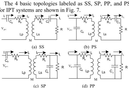
The 4 basic topologies labeled as SS, SP, PP, and PS for IPT systems are shown in Fig. 7.
Cp Rp
Lp Ls
Rs Cs
R Ip Is
IL Ii
Vp-v
M
Rp
Lp Ls
Rs Cs
R Cp
Vp-c
M
Ip Is IL
Ii
(a) SS (b) PS
Cp Rp
Lp
Vp- v
M
Ls Rs
R Cs
Ip Is I
L
Ii
Rp
Lp Ls
Rs
R Cp
Vp- c
M
Cs
Ip Is I
L
Ii
(c) SP (d) PP Figure. 7 4 basic topologies of IPT system
Where, the first S or P presents for series or parallel compensation of the primary circuit, the second S or P presents for series or parallel compensation of the secondary circuit.
Take SS topology IPT system as an example, the power transfer capability of IPT system was analyzed using an identical method, and the other topologies can be analyzed in the same method.
Because that the resonant angle frequency of IPT system is very high. In the real system, the impedance of compensation inductor Ls is negligible, in the following analysis, the Rs will not be considered.
From (19)~(22), we can see that, in order to realize maximum power transfer for IPT system, the compensation capacity Cp and mutual inductance M exists an optimized value.
With the same method used as (19)~(22), the compensation capacity Cp and mutual inductance M of the 4 basic topologies are shown in Tab. 2.
TABLE.II.
OPTIMIZED PARAMETERS OF THE 4 TOPOLOGIES
topology Cp
SS 2
1
p L
ω
PS
2
2 2 2 4 4 2 2 2 2 2
p
p p p
L R
L R M M RR R R
ω +ω + ω +
SP 2 2 2
1
p s M L
L
ω ω −
PP
2 2 4 2 2 3 4 2
2 2 3 2 4
2 4 2 2 2 4 2
2 2 3 2 4
2
2
p s p s s p
s p s
s s p
s p s
L L M L L L R
M L L L
M L L M RR M R
M L L L
ω ω
ω ω
ω
ω ω
− +
−
+ +
+
−
(a) Primary capacitance
topology Mopt
SS R Rp
ω
PS
(
)
2 2 2 2
4
p p
L R R
ω ω
+
SP Ls RP
R
PP
2 2 2
4
2 2 2
p p
s s
L R
L
L R
ω ω
+ +
(b) Optimized mutual inductance
From Tab. 2, we can see that in order to realize maximum power transfer for IPT system, the compensation capacity Cp and mutual inductance M exists an optimized value.
As the mutual inductance M satisfies p s
So, the value of mutual inductance M exists an upper
limit, if the optimized value calculated from theory analysis exceeds the upper limit, the optimized value is not exist.
VI. PARAMETER OPTIMIZATION EXPERIMENT OF CPT AND IPTSYSTEM
A. Power Transmission Experiment of CPT and IPT System
The actual CPT and IPT system structures shown in Fig. 2 are established for parameter optimization and simulation.
(A) For the CPT and IPT system with coupling body and the frequency f is the same, in the case of the same input voltage, set the CPT system and the IPT system parameters shown in Tab.3.
TABLE III.
PARAMETERS OF THE SYSTEM (ONE)
other parameters
Vp/V f/kHz r/m d/m
10 100 0.05 0.01
CPT ε0/F/m εr tanδ
8.854×10⁻¹² 1 0.0007
IPT N1 N2 ρ/Ω.mm2/m D/m
5 5 0.0175 0.001
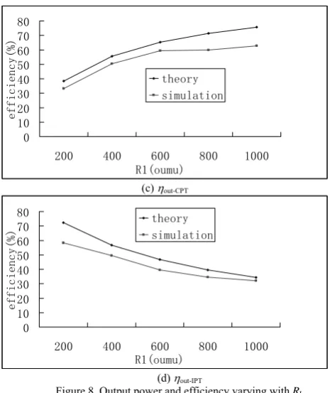
According to the theoretical analysis and simulation, the curve of the output power and efficiency varying with the load resistor RL of CPT and IPT system can be shown in Fig. 8.
0 0.02 0.04 0.06 0.08 0.1
200 400 600 800 1000
R1(oumu)
P
out-CPT(W)
theory simulation
(a) Pout-CPT
0 100 200 300 400 500 600 700 800
200 400 600 800 1000
R1(oumu)
Po
ut-IP
T(W
)
theory simulation
(b) Pout-IPT
0 10 20 30 40 50 60 70 80
200 400 600 800 1000
R1(oumu)
effic
iency(%
)
theory simulation
(c) ηout-CPT
0 10 20 30 40 50 60 70 80
200 400 600 800 1000
R1(oumu)
efficie
ncy(%)
theory simulation
(d) ηout-IPT
Figure 8. Output power and efficiency varying with RL
(B) For the CPT and IPT systems with same coupling body and the load resistor RL, in the case of the same input voltage, set the CPT system and the IPT system parameters shown in Tab. 4.
TABLE IV.
PARAMETERS OF THE SYSTEM (TWO)
other parameters
Vp/V RL/Ω r/m d/m
10 2 0.05 0.01
CPT ε0/F/m εr tanδ
8.854×10⁻¹² 1 0.007
IPT N1 N2 ρ/Ω.mm2/m D/m
5 5 0.0175 0.001
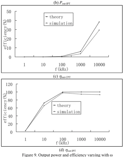
According to the theoretical analysis and simulation, the curve of the output power and efficiency varying with
f of CPT and IPT system are shown in Fig. 9.
0 2 4 6 8
1 10 100 1000 10000 f(kHz)
Pout
-CPT(
W)
theory simulation
(a) Pout-CPT
0 100 200 300 400 500 600
1 10 100 1000 10000
f(kHz)
Pout-IPT(
W)
(b) Pout-IPT
0 10 20 30 40 50
1 10 100 1000 10000 f(kHz)
effi
cien
cy(%)
theory simulation
(c) ηout-CPT
0 20 40 60 80 100 120
1 10 100 1000 10000 f(kHz)
eff
icien
cy(%
)
theory simulation
(d) ηout-IPT
Figure 9. Output power and efficiency varying withω Fig. 8 and Fig. 9 show that the results of theoretical analysis and simulation are basically the same, in the same working environment: the IPT system has higher power transmission capacity and efficiency than the CPT system.
In order to improve the power transmission capacity and efficiency of the CPT system, the system frequency should be improved, in order to achieve a few watts of power transmission, the system operating frequency usually require up to tensof megabytes or even hundreds of megabytes Hz, which is difficult to achieve in the actual application system. But in the environment containing metal shield, the power transmission capacity and efficiency of the IPT system will be seriously limited, while the power transmission capacity and efficiency of the CPT system will be improved. Therefore, the CPT system is generally used only for signal transmission, low power transmission, and an environment containing metal shield, the high-power applications is very restricted.
B. Mutual Inductance Optimization Experiment for IPT System
In order to verify the correctly of mutual inductance optimization, the parameters of IPT system are designed as in Tab.. 5
TABLE.V PARAMETERS OF SYSTEM
Vdc/V Lp/µH Rp/Ω ω/rad/s
10 100 0.2 125600
Ls/µH Cs/µF Rs/Ω R /Ω
64 0.99 ≈0 10 From(30), we can see that the value range of mutual inductance is (0,80uH). According to the theory analysis, the curves of output power of IPT system with
the 4 topologies varying with mutual inductance are shown in Fig.10.
0 20 40 60 80 100 120
5 10 20 30 40 50 60 70 80 M(uH)
Po
ut(
W)
theory simulation experiment
(a) SS
0 20 40 60 80 100 120
1 2 3 4 5 6 7 8 9
M(uH)
Po
ut(W
)
theory simulation experiment
(b) SP
0 1 2 3 4 5
5 10 20 30 40 50 60 70 80
M(uH)
P
out
(W)
theory simulation experiment
(c) PS
0 2 4 6 8 10 12
1 2 3 4 5 6 7 8 9
M(uH)
Po
ut(W
)
theory simulation experiment
(d) PP
Figure. 10 Transmission power varying with M of ICPT system with the four topologies
From Fig.10, we can see that, for SS and SP topology IPT system, when the mutual inductance is 10uH, the
VII. CONCLUSION
From the perspective of power transfer characteristic, the paper has made a comparative analysis between CPT and IPT technology in the same environment. Firstly, the paper has obtained their maximum power transmission capacity and the establishment of conditions; at the same time, the power transmission capacity of the two structures were compared and analyzed; then the characteristics of two structures through the same application environment was analyzed; and the different environments under the principle of contactless power transfer system selection basis was given.
ACKNOWLEDGMENT
The authors wish to thank Professor Yue Sun, and Xin Dai, College of Automation Chongqing University, Chongqing, China. They have supplied greate support for this paper. And we all wish to thank School of Environment Science and Spatial Informatics, China University of Ming and Technology, This work was supported in part by a grant from them.
REFERENCES
[1]. Elliott G., Raabe S, Covic G. A., Boys J.T. “Multiphase Pickups for Large Lateral Tolerance Wireless Power-Transfer Systems”. IEEE Transactions on Industrial Electronics. vol.57, no.5, pp: 1590-1598, 2010.
[2]. Boys J T, Covic G A, Yongxiang X. “DC analysis
technique for inductive power transfer pick-ups”. IEEE Power Electronics Letters, vol.1, no.2, pp: 5135-5136, 2003.
[3]. Hu A P, Covic G A, Boys J T. Direct ZVS start-up of a current-fed resonant inverter[J]. IEEE Transactions on Power Electronics, 2006, 21(3): 809-812. vol.21, no.3, pp: 809-812. 2006.
[4]. Matsuda Y, Sakamoto H. “Non-contact magnetic coupled power and data transferring system for an electric vehicle”. Journal of Magnetism and Magnetic Materials, vol.310, no.2, pp: 2853-2855. 2007.
[5]. Hatanaka K, Sato F, Matsuki H, et al. “Power
transmission of a desk with a cord-free power supply”. IEEE Transactions on Magnetics, vol.38, no.5, pp: 3329-3331. 2002.
[6]. Hirai J, Tae-Woong K, Kawamura A. “Integral motor
with driver and wireless transmission of power and information for autonomous subspindle drive”. IEEE Transactions on Power Electronics, vol.15, no.1, pp: 13-20. 2000.
[7]. Sun Yue,Xia Chenyang,Dai Xin,Su Yugang.
“Analysis and Optimization of Mutual Inductance for Inductively Coupled Power Transfer System”. Proceedings of the CSEE, vol.30, no.33, pp: 44-50. 2010. [8]. Wang Lu, Chen Min, Xu Dehong, et al. “The engineering
design of wireless emergency power supply in maglev”. Proceedings of the CSEE, vol.27, no.18, pp: 67-70. 2007.
[9]. MA Hao, SUN Xuan. “Design of Voltage Source
Inductively Coupled Power Transfer System With Series Compensation on Both Sides of Transformer”. Proceedings of the CSEE, vol.30, no.5, pp: 48-52. 2010.
[10]. Chao L, Aiguo PH. “Steady state analysis of a
capacitively coupled wireless power transfer system”. IEEE Energy Conversion Congress and Exposition, ECCE2009.SanJose, CA, United states: IEEE Computer Society. pp: 3233-3238. 2009.
[11]. Hu Youqiang, Dai Xin “Study on modeling of
capacitively coupled wireless power transfer system sing generalized state space averaging method”. Chinese Journal of Scientific Instrument. vol.31, no.9, pp: 2133-2139. 2010.
[12]. Qiaowei Yuan, Qiang Chen, Long Li, and Kunio Sawaya. “Numerical analysis on transmission efficiency of evanescent resonant coupling wireless power transfer system”. IEEE transactions on antennas and propagation. vol.58, no.5, pp: 1751-1758. 2010.
[13]. Anil Kumar RamRakhyani, Shahriar Mirabbasi, Mu Chiao. “Design and optimization of resonance-based efficient wireless power delivery systems for biomedical implants”. IEEE transactions on biomedical circuit and systems, pp: 1-16. 2010.
[14]. K. Finkenzeller. “RFID-Handbook”, 2nd Ed. Wiley,
Hoboken, NJ, 2003
Chenyang Xia was born in China in 1982. He received the B.S. M.S. and Ph.D degree in control theory and control engineering from Chongqing University, Chongqing, China, in 2006, 2008 and 2010 respectively.
He is currently working in Information and Electrical Engineering, China University of Mining and Technology, Xuzhou, China. His current research interests include intrinsic safety switch power supply and wireless power transfer.
Yuejin Zhou was born in China in 1974. He received the B.S. and M.S. degrees in mineral engineering from China University of Mining and Technology, Xuzhou, China, in 1997 and 2005, respectively, He is currently working toward the Ph.D. degree in School of Environment Science and Spatial Informatics, China University of Mining and Technology
He is currently the lecturer of School of Information and Electrical Engineering, Xuzhou Institute of Architectural Technology, Xuzhou, China. His current research interest is square set and back filling method.
Juan Zhang was born in China in 1983. She received the B.S. degrees in computational Mathematics from Chongqing Three Gorges College, Chongqing, China, in 2006, and the M.S. degree from Chongqing University, Chongqing, in 2009.
Ms Zhang is currently the lecturer of Jiangsu Provincial Xuzhou Pharmaceutical Vocational College.
Chaowei Li was born in China in 1984. He received the B.S. and M.S. degree in control theory and control engineering from Chongqing University, Chongqing, China, in 2006 and 2009 respectively.