A Study on Tall RC Structure with Lateral Force
Resisting System Subjected to Seismic Loading
Mr. Rohit V. Mashalkar Mrs. Trupti Narkhede
PG Student Assistant Professor
Department of Civil Engineering Department of Civil Engineering
MGM’S college of Engineering, Kamothe, Navi Mumbai MGM’S college of Engineering, Kamothe, Navi Mumbai
Mr. P. J. Salunke Head of Department Department of Civil Engineering
MGM’S college of Engineering, Kamothe, Navi Mumbai
Abstract
Finite Element Analysis of the tall slender RC structure with RC shear wall, Steel Plate Wall, Bracings And without any lateral force resisting system has been carried out to study. The behavior of tall RC structure in terms of time period, base shear, Mode shape, story displacement & story drift. Due to Application of various Time history Earthquake loading is studied. The three dimensional model has been considered and analyzed for the gravity loading, seismic loading, for seismic loading both Response spectra Method and Time history Method has been carried out IS 1893:2002 has been used for seismic loading calculation and analysis.
Keywords: RC shear wall, steel plate wall, Bracings, Time History, response spectrum, tall Building
________________________________________________________________________________________________________
I. INTRODUCTION
A good Lateral Load resisting structural system can ensure inelastic behavior by having greater redundancy, thereby having larger ductility and damping. The choice of the structural system is often dictated by the architectural consideration in addition to the intended function & seldom by the structural strength and stiffness considerations which make the structure vulnerable to seismic actions. Engineers are required to select an appropriate structural system to resist the lateral (seismic) forces together with the functional & architectural constraints. It is very much essential that all the lateral load-resisting structural components need to be rigidly connected. It is necessity to ensure the predictable and well-thought-out path of the resistance for the lateral forces in a structural system. In general the structural system of building is a complex in assembling of various combinations of structural Elements. The primary function of structural system is to carry dynamic and static loads, external or internal explosion and impact loads. A variety of factors has to be considered in the process of selecting most suitable structural system for tall building. The selection is complicated process, and no simple clear cut process available.
Steel Plate Shear Wall System:
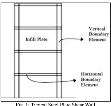
Fig. 1: Typical Steel Plate Shear Wall
element (beams). Together, the steel plate wall and boundary columns act as a vertical plate girder. The columns act as flanges of the vertical plate girder and the steel plate wall acts as its web.
The main function of steel plate shear wall is to resist horizontal story shear and overturning moment due to lateral loads. Steel plate shear walls (SPSW) can be used as a lateral load resisting system for buildings. A typical SPSW (Fig. 1) consists of stiff horizontal and vertical boundary elements (HBE and VBE) and infill plates. The resulting system is a stiff cantilever wall which resembles a vertical plate girder.
Braced Frame System:
Bracings are strong in compression. Bracing with their surrounding frames has to be considered for increase in lateral load resisting capacity of structure. When bracings are placed frame it behaves as diagonal compression strut and transmits compression force to another joint. The structure with braced frame is supposed to perform better, Braces can be configured as diagonal (X) these structures with braced frame increase the lateral strength and also the stiffness of the structural system.
II. OBJECTIVES OF STUDY
1) To prepare a three dimensional model in ETABS and to analyze the structure using Finite element analysis approach. 2) To study various parameters such as First 3 Mode shapes Building, Time Period of First 3 modes of building. 3) To study Modal Mass Participation ratio of first 12 modes.
4) Maximum Top Story Displacement of Building for earthquake load (X & Y Direction). 5) Floor Wise Story Displacement of Building (X & Y Direction).
6) Base Shear of each Building for each earthquake load (X & Y Direction). 7) Floor Wise Story Drift of each Building (X & Y Direction).
8) Critical Column Axial Load of each Building for each earthquake load (X & Y Direction).
9) To compare the effect of various systems by both Dynamic Analysis method (Response spectrum method) And Time History Analysis.
III. METHODOLOGY
The said structure is modeled as three dimensional structure and all the loads are applied, gravity loading such as dead load and live load in the direction of gravity, lateral loads such as seismic and the behavior of the structure has been studied and it has been insured the drift and displacements are within the limits specified by Indian standards
Model Data
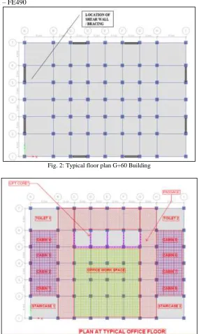
Building Considered for the present study is “Rectangular” shaped High rise commercial building with Ground + 60 stories. Dimensions and other details are as follows-
Shape of Building – “Rectangular” shaped. Ground + 60 Storied Building.
Column to Column Grid spacing considered is 5 m at first & last grid, 3m at all other grids. Number of Grids Considered in X Direction are 9 Nos.
Overall Dimension of Building in X Direction = 28 m Number of Grids Considered in Y Direction are 7 Nos. Overall Dimension of Building in X Direction = 20 m. Total Height of Building above Ground Floor = 180 m.
Section Properties
External Beam = Steel girder450 x 300 x 25 Size of Internal Beam = ISMB 450.
Slab =175mm Steel Plate = 8mm Bracings = ISMB 300
RCC Shear Wall=250mm
Sr. No. Levels Column Size (mm) Concrete Grade
1. Ground to 10th 700 x 700 M50
2. 11th to 20th 600 x 600 M50
3. 21st to 30th 500 x 500 M50
4. 31st to 40th 400 x 400 M50
Material Properties
Column & shear wall=M50 Slab =M30
Reinforcement=FE500
Fe490 for structural steel – FE490
Fig. 2: Typical floor plan G+60 Building
Fig. 2: Typical floor plan G+60 Building
Gravity loading
Floor Finish – 0.75 kN/m2 Water proofing – 0.75 kN/m2 Live Load – 4 kN/m2
Wall load 200 mm thk. – 14.2 kN/m, Wall load 150 mm thk. – 5.4 kN/m parapet wall load – 3.8 kN/m
Seismic loading
Building Frame Systems – Ductile shear walls
Response reduction factor – 5, Table 7 of IS1893:2002 Soil Type – II, Hard soil, Table 1 of IS1893:2002 Importance factor – 1, Table 6 of IS1893:2002 Time Period – Program Calculated
No. of modes to be considered – 12 Modal Analysis – Eigen
Modal combination – CQC, cl 7.8.4.4 of IS1893:2002 Directional combination – SRSS
Initial scale factor – Ig/2R Minimum eccentricity – 0.05
Damping – 5 percent, cl 7.8.2.1 of IS1893:2002 Mass source – 1DL + 0.25 LL
Diaphragm type – Semi rigid
Load case
DL – Self weight of structure SDL – floor finish, waterproofing LIVE – live load on floors
TERRACE LIVE – Live load on terrace EQX, EQY – Seismic load
SPECX, SPECY – Response spectrum case
Load Combinations
Limit state of strength 1.5DL
1.5DL+1.5LL 1.5DL+1.5EQ 0.9DL+1.5EQ 1.2DL+1.2LL+1.2EQ Limit state of Serviceability
1DL
1DL+1LL
1DL+1EQ
1DL+0.8LL+0.8EQ
Method of Analysis
Following analysis has been carried in addition to analysis for gravity loading. Seismic analysis
Dynamic method -Response spectrum method a)Time History Analysis
Following Types of Earthquake History have been considered in this study. Bhuj Time History
Koyana Time History
North-East 1988 Time History
Total Four Analysis Models are prepared as Mentioned following.
1) Model 1 - Building with Beam Column frame as Lateral Load resisting system.
2) Model 2 - Building with Beam Column frame + Concrete shear wall as Lateral Load resisting system. 3) Model 3 - Building with Beam Column frame + Steel Plate shear wall as Lateral Load resisting system. 4) Model 4 - Building with Beam Column frame + Steel Bracing as Lateral Load resisting system
IV. RESULTS AND DISCUSSION
Time Period
Most of the forces applied on the Building are directly related to its Time Period. Thus variation in Time Period helps us to understand overall behavior of Building after introducing various types of Lateral load resisting system.
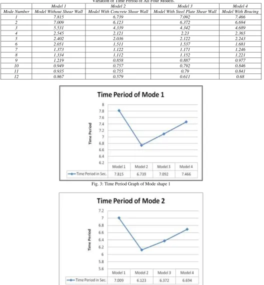
Following Table shows comparison of Time Period of First 12 modes of Each Building Models considered in this study- Table – 1
Variation of Time Period of All Four Models.
Model 1 Model 2 Model 3 Model 4
Mode Number Model Without Shear Wall Model With Concrete Shear Wall Model With Steel Plate Shear Wall Model With Bracing
1 7.815 6.739 7.092 7.466
2 7.009 6.123 6.372 6.694
3 5.531 4.339 4.342 4.689
4 2.545 2.121 2.23 2.365
5 2.402 2.036 2.122 2.243
6 2.051 1.511 1.537 1.681
7 1.373 1.122 1.171 1.246
8 1.334 1.112 1.152 1.221
9 1.219 0.858 0.887 0.977
10 0.949 0.757 0.792 0.846
11 0.935 0.755 0.79 0.841
12 0.867 0.579 0.611 0.68
Fig. 3: Time Period Graph of Mode shape 1
Fig. 5: Time Period Graph of Mode shape 3
Maximum Top Story Displacement:
High Rise Buildings are more susceptible to Earthquake induced forces. Limit state of serviceability states that inhabitant of the building should not experience motion sickness due to lateral deflection or vibration of the building. Indian Standard code IS 1893 & IS456 specifies Lateral Sway limit for earthquake and wind induced forces.
In general Lateral Sway Limit for Building = 180 / 250 = 720 mm
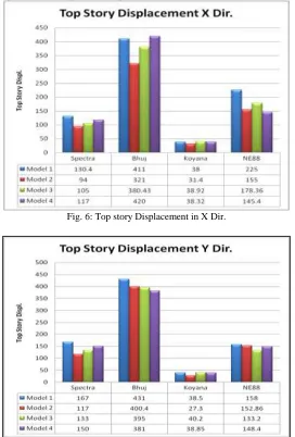
Following Table represents Comparison for Top Story Displacement between All four Models for each Earthquake Load.
Fig. 6: Top story Displacement in X Dir.
Floor Wise Story Displacement:
Following Graphs represents Comparison for Floor wise Story Displacement between All four Models for each Earthquake Load
Fig. 8: story Displacement in X Dir
Fig. 9: story Displacement in Y Dir
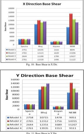
Base Shear Comparison:
Fig. 10: Base Shear in X Dir.
Fig. 11: Base Shear in Y Dir.
Story Drift Comparison
Fig. 13: Story Drift in Y Dir.
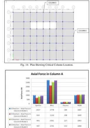
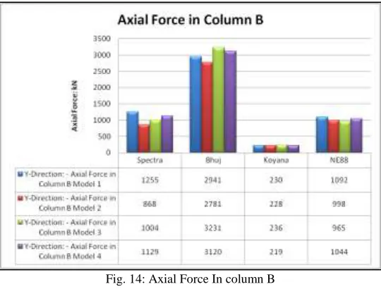
Critical Column Axial Force Comparison:
Maximum Axial Load has been compared for all earthquake loads for columns shown below.
Fig. 14: Plan Showing Critical Column Location.
Fig. 14: Axial Force In column B
V. CONCLUSION & FUTURE COPE OF STUDY
The most effective and deciding basic parameter studied during this whole analysis was drift and deflection of the structure. The following conclusions are made from the present study.
Time Period
Time period of the structure has reduced after application of Shear wall & Bracing. However no changes are observed in Mode shape Pattern Following are observations on reduction in Time Period with respect to Model without Shear wall/Bracing.
Table – 2
Time Period Comparison for Mode Shape.
Description Model with Concrete Shear Wall Model with Steel plate Wall Model with Bracing
MODE 1 13.80% 9.30% 4.50%
MODE2 12.70% 9.10% 4.50%
MODE3 21.60% 21.50% 15.20%
Modal Mass Participation
Modal Mass participation is more or less directly proportionate to time period of the structure, however it is observed that, X direction and Y direction mass participation has increased for Model with Concrete Shear wall Compared to the other model.
Maximum Top Storey Displacement
In this study it is generally observed that Top story displacement in X direction of the structure has reduced after introduction of Shear Walls / Bracing for all applied Earthquake loads. Similar observations are there for Y Direction Earthquake Loads. Following are observations on reduction in Max Top story displacement with respect to Model without Shear Wall / Bracing.
Table – 3
Story Displacement in X& Y Dir.
EQ Data: Model 1 Model 2 % Comparison w.r.t. Model 1
Model 3 % Comparison w.r.t. Model 1
Model 4 % Comparison w.r.t. Model 1
mm mm % mm % mm %
Spectra 130.4 94 27.9 105 19.5 117 10.3
Bhuj 411 321 21.9 380.43 7.4 420 -2.2
Koyana 38 31.4 17.4 38.92 -2.4 38.32 -0.8
NE88 225 155 31.1 178.36 20.7 145.4 35.4
EQ Data: Model 1 Model 2 % Comparison w.r.t. Model 1
Model 3 % Comparison w.r.t. Model 1
Model 4 % Comparison w.r.t. Model 1
mm mm % mm % mm %
Spectra 167 117 29.9 133 20.4 150 10.2
Bhuj 431 400.4 7.1 395 8.4 381 11.6
Koyana 38.5 27.3 29.1 40.2 -4.4 38.85 -0.9
NE88 158 152.86 3.3 133.2 15.7 148.4 6.1
Max. X DIRECTION Top Story Displacement
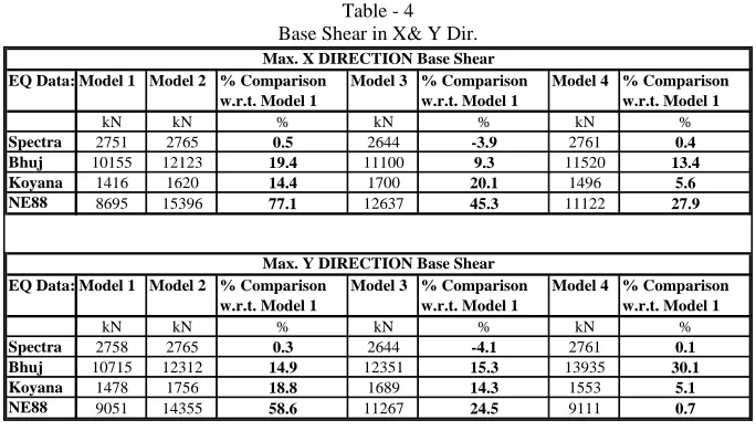
Base Shear
Below comparison table shows % variation of Base shear w.r.t. Model without shear wall: Table - 4
Base Shear in X& Y Dir.
Floor Vise Story Drift
In this study it is generally observed that floor vise story Drift in X as well as Y direction of the structure has reduced more significantly for Model with Concrete shear wall (than model with steel plate shear wall and bracings) as compared with model without shear wall
Column Forces at Ground Floor
Two Critical Columns has been compared w.r.t. axial forces for different earthquake loads in X & Y directions. It is generally observed that column forces in two critical columns are reduced after introduction of Shear walls & Bracing in most of the Earthquake loads applied.
Thus from Above all comparisons & observations it can be globally concluded that Model with Concrete Shear Wall has shown significant effect on all comparative parameters considered. The model with Concrete shear wall has shown considerable variation in results w.r.t. Model without shear wall as compared with Model with Steel Plate Shear Wall & Model with steel bracing.
Scope of future study
1) More detailed analysis such as Pushover analysis and will carried out of the said structure and their results will be compared 2) Structural design of the members namely beam, column slab, shear wall will be done
3) Ductile detailing of the structure will be done
4) Further optimization of the sizes of the members will be done
5) Analysis will be done on one unsymmetrical plan and the results will be compared with the symmetrical layout plan. 6) Lateral Resisting systems with tall steel building can be compared with RCC & Composite building.
7) Cost Comparative study can be don
REFERENCES
[1] Dr. Vinod Hosur – “Earthquake – Resistant Design of Building Structures” willey publications, first edition 2013.
[2] Narasimha M.(2016), “Effective Study of Bracing Systems for Irregular Tall Steel Structures”, International Journal of scientific & Engineering Research, Volume 7, Issue 5, May (2016), ISSN: 2229-5518
[3] V.Mhalungkar (2012), “Seismic Analysis of High Rise steel Frame With and Without Bracing”,15 WCEE LISBOA 2012
[4] Sucheta Jagtap (2016), “Seismic Analysis of Lateral Force Resisting systems for tall Buildings”, International Journal of scientific & Engineering Research Volume 2, Issue 4, May (2016), IJARIIE-ISSN(O)-2395-4396
[5] Jeffrey W. Berman, Oguz C. Celik, Michel Bruneau; (2005) “Comparing hysteretic behavior of light-gauge steel plate shear walls and braced frames”, University at Buffalo, USA. Engineering Structures 27 ,475–485.
[6] P. P. Chandurkar, Dr. P. S. Pajgade; (2013) “Seismic Analysis of RCC Building with and Without Shear Wall”, International Journal of Modern Engineering Research (IJMER) Vol. 3, Issue. 3, PP-1805-1810
[7] Mahmoud REZAI, Carlos E VENTURA and Helmut G L PRION (2000), “Numerical investigation of thin unstiffened steel plate shear walls”, 12th World Conference on Earthquake Engineering 2000 pp 1-4.
[8] Sabouri-Ghomi, S., C.E. Ventura and M.H.K. Kharrazi (2005), “ShearAnalysis and Design of Ductile Steel Plate Walls”, J. Structural Engineering ASCE, 6: 878-889.
[9] Adithya. M (2015), “Study On Effective Bracing Systems for High Rise Steel Structures”, SSRG International Journal of Civil Engineering (SSRG-IJCE) – volume 2 Issue 2 February2015ISSN:2348–8352.
EQ Data: Model 1 Model 2 % Comparison w.r.t. Model 1
Model 3 % Comparison w.r.t. Model 1
Model 4 % Comparison w.r.t. Model 1
kN kN % kN % kN %
Spectra 2751 2765 0.5 2644 -3.9 2761 0.4
Bhuj 10155 12123 19.4 11100 9.3 11520 13.4
Koyana 1416 1620 14.4 1700 20.1 1496 5.6
NE88 8695 15396 77.1 12637 45.3 11122 27.9
EQ Data: Model 1 Model 2 % Comparison w.r.t. Model 1
Model 3 % Comparison w.r.t. Model 1
Model 4 % Comparison w.r.t. Model 1
kN kN % kN % kN %
Spectra 2758 2765 0.3 2644 -4.1 2761 0.1
Bhuj 10715 12312 14.9 12351 15.3 13935 30.1
Koyana 1478 1756 18.8 1689 14.3 1553 5.1
NE88 9051 14355 58.6 11267 24.5 9111 0.7
Max. X DIRECTION Base Shear