Effect of Parametric Variation on the Offset Finned
Absorber Solar air Heater
Shalini Rai, Prabha Chand, S.P.Sharma
Mechanical Engineering Department, NIT Jamshedpur, Jharkhand (India)
*Corresponding Author: Shalini Rai; NIT Jamshedpur, Tel:+9896338256, [email protected]
Abstract-- In this approach, MATLAB has been used for theoretical investigation on performance of offset finned absorber solar air heater. The evaluation of parametric effect i.e. offset fin spacing ‘sf’ and offset fin height ‘hf’ and solar insolation ‘Io’ at different air mass flow rate on the thermal and exergy performance of solar air heater. Thermal efficiency (the first law of thermodynamic) and exergy efficiency (the efficiency of process taking the second law of thermodynamic in account), the results indicate that the exergy performance is effective at lower air mass flow rate, fin spacing and fin height, whereas the thermal performance at higher air mass flow rate. The exergy efficiency is the main factor for performance evaluation, results show that the trends of variation of the thermal and exergy efficiencies are not the same. The performances of offset finned solar air heater are compared with conventional flat plate solar air heater.
Index Term-- MATLAB, thermal efficiency, exergy efficiency, offset fin, parametric study.
1. INTRODUCTION
Today, solar air heaters are the system which uses the solar energy to fulfill the general requirement in the field of space heating, agricultural and crop drying etc. solar air heaters are widely employed due to simplicity in design, maintenance as well as low cost of materials required for construction. Nevertheless, in spite of these multiple benefits of solar air
heaters, their fundamental deficiency is the low rate of heat transfer between absorber plate and flowing air due to unpropitious thermo-physical properties of air. So that the different researchers [1-6] have centralize their studies toward assorted performances method and used different strategies for increasing the heat-transfer coefficient between the absorber plate and flowing air through the channel include the use of fins ,corrugated surface, packed bed and fin with baffles configurations have been investigated.
In order to balance the quality of energy gain and friction losses, the exergy analysis is more appropriate in comparison to the thermal analysis, [7-9] studied the exergetic performance of a solar air heater having discrete V-down rib roughness and compared the obtained results with a conventional flat-plate solar air heater. The exergetic performance evaluation of solar air heater with arc-shaped wire rib roughened absorber plate investigated [10]. Results showed that the exergy analysis is one of the important methods to evaluate the performance of solar air heater. Sahu, M.K., and Prassad, R.K. [11]
investigated on exergetic performance evaluation of solar air heater with arc-shaped wire rib roughened absorber plate.
Results showed that the exergy analysis is one of the important methods to evaluate the performance of solar air heater.
NOMENCLATURE
length of the solar collector (m) incoming exergy in the control volume
width of the solar collector (m) outgoing exergy from the control volume
duct height of the solar collector (m) exergy efficiency
length of the offset fin (m) exergy of solar radiation falling on glass cover
height of offset fin (m) inlet fluid temperature in the solar collector (K)
thickness of offset fin (m) outlet fluid temperature from the solar collector (K)
fin spacing of offset fin (m) sun temperature (K)
equivalent hydraulic diameter of solar collector (m)
exergy efficiency or second law efficiency
total surface area of the fins ( ) friction factor
, elemental surface area of the solar
collector (
Pressure drop(N/ )
cross surface area of the solar collector duct ( )
required pump work
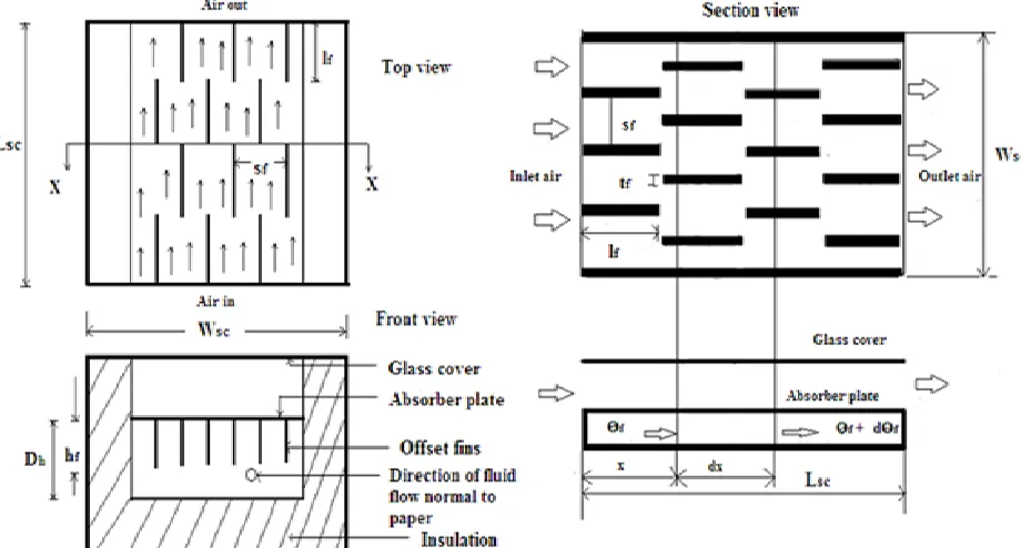
Considered the offset finned below the absorber plate solar air heater as shown in Fig.1.The channel of width ,duct height, and length of the collector absorber plate „ ‟, „ ‟ and „ ‟
respectively having one glass cover is uniformly heated from
top by solar radiations transmitted through the glass cover. The height „ ‟, length„ , thickness „ ‟ and spacing „ ‟ of the offset fin.
Fig. 1. Sectional view of absorber plate attached with offset fins.
2.1Thermal efficiency
The thermal efficiency can be expressed as:
̇ (
(1)
2.2 Exergy analysis
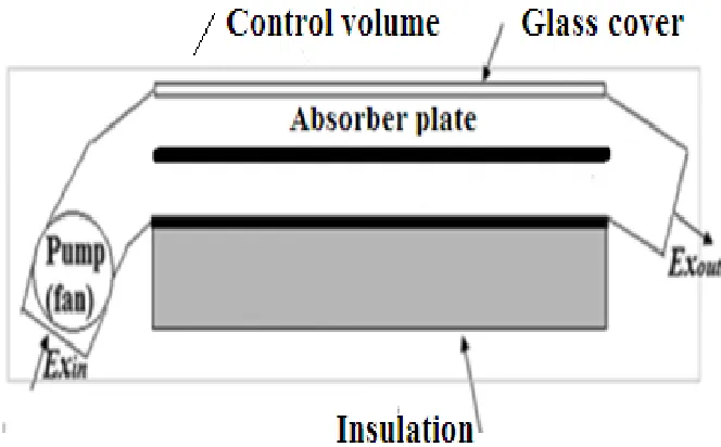
A fundamental difference between thermal and exergy is that while the former is conserved, the latter is destroyed in all real processes due to irreversibilities. Fig. 2 illustrates that Exergy is lost in two different ways. Internal losses (“destruction”) are caused by irreversibilities in the process (heat transfer,
chemical reaction, mixing, unrestricted expansion, etc.); while external losses (“leakage”) are caused by exergy content in effluent streams that are not utilized (exhaust gases, purge and bleed streams, cooling water, etc.) An efficiency based on total Exergy would only account for internal losses (irreversibilities) in the process.
Fig. 2. Exergy Flows entering and exiting a Process.
Considered the control volume illustrated in Fig.3. The exergy balance equation of solar air heater recommended by
Fig. 3. Considered control volume (CV) for the solar air heater
(2)
and are the exergy associated with the mass flow of
flowing air come in and come out the control volume, respectively. The exergy of solar radiation falling on glass cover , exergy of the input work required pumping the air
through the solar air heater and the irreversibility of the air heating process IR. The irreversibility or exergy loss occurs due to the temperature difference between absorber plate surface and sun, heat losses to the ambient and pressure drop in channel.
and are:
( ( (3)
( ( (4)
The calculated as [12]:
( ( ) ( (5)
where exergy efficiency is
Considered the pressure drop and assuming air as an incompressible fluid or perfect gas, the useful exergy gain,
is expressed as:
̇ *(
(
)+ (6)
The term (
⁄ is the exergy destruction due to pressure drop. The required pump work is:
̇ ( (7)
The following correlation of friction factor is developed for calculating the pressure drop [13]
, the pump motor efficiency and is taken to be 0.85
[12].The exergy efficiency, called second law efficiency, of the solar air heater is calculated by dividing the useful exergy gain to the exergy solar radiation as:
( ( ) (
(9)
3. CALCULATION PROCEDURE
Procedures followed for determination of the thermal and exergy performance evaluation of offset finned absorber solar air heater listed in Table I.
Step-1 Assumed initial value of absorber mean
temperature , air stream temperature and bottom mean temperature .
Step-2 Find out convective heat transfer coefficient by
using Eqs. (9) and (10) Shalini rai et al [14]
Step-3 , and were checked using Eqs. (4), (5)
and (6) from [14] and the calculated values of temperature were compared with the initial assumptions of temperature. If difference between calculated values and initial guess values were less than 0.001, assumed temperature values were considered correct; otherwise, the procedure was repeated until the values reached to a convergence.
Step-4 Upon completion of step (3), the values of mean
temperatures were calculated and the exergy efficiency was calculated via Eq. (9).
4. RESULTS AND DISCUSSION
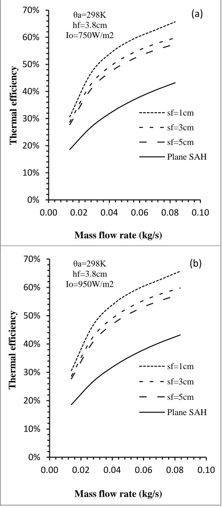
Fig. 4. Thermal efficiency vs. mass flow rate for various fin spacing (a) Io=750W/m2, (b) Io=950W/m2.
It is seen that use of attaching offset finned below the absorber plate lead to higher thermal efficiency as compared to a conventional (plane) solar air heater. It has been found that the thermal efficiency monotonically increases with an increase in mass flow rate apparently because of an increase in the convective heat transfer coefficient. The lowest fin spacing (1cm) maintains the highest efficiency value throughout the range of mass flow rate investigated. Furthermore, a slightly fall is observed in the rate of increase of efficiency as mass flow rate increases apparently due to relatively lower percentage increase in surface conductance as mass flow rate increases as also due to relatively higher heat flow rate. Also increase in fin spacing decreases the thermal efficiency of solar air heater. This is due to facts that increase in fin spacing resulted in decrease in heat transfer surface area and hence heat transfer rate.
Figs.5 (a) and (b) show variation of thermal efficiency as a function of mass flow rate for different fin height and insolation for Io=750W/m2 and Io=950W/m2. From the figure it is seen that thermal efficiency increases with increase in mass flow rate. It is also observed that increase in height of offset fin slightly decreases the thermal efficiency of solar air heater. This is because of increase in offset fin height increase the heat transfer surface area; however it decreases the convective heat transfer coefficient.
0% 10% 20% 30% 40% 50% 60% 70%
0.00 0.02 0.04 0.06 0.08 0.10
T
herm
a
l
ef
ficiency
Mass flow rate (kg/s) θa=298K
hf=3.8cm Io=750W/m2
sf=1cm
sf=3cm
sf=5cm
Plane SAH
(a)
0% 10% 20% 30% 40% 50% 60% 70%
0.00 0.02 0.04 0.06 0.08 0.10
T
herm
a
l
ef
ficiency
Mass flow rate (kg/s) θa=298K
hf=3.8cm Io=950W/m2
sf=1cm
sf=3cm
sf=5cm
Fig. 5.Thermal efficiency vs. mass flow rate for various fin height (a) Io=750W/m2, (b) Io=950W/m2.
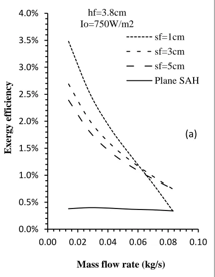
Figs.6 (a) and (b) show variation of exergy efficiency with mass flow rate for different fin spacing and for insolation Io=750W/m2 and Io=950W/m2 .It is clearly seen that attaching offset fins below the absorber plate, lead to exergy efficiency increase compared to a plane solar air heater. From the figure it is also observed that decrease in fin spacing gives higher exergy efficiency at lower mass flow rate for Io=750W/m2 and Io=950W/m2; the improvement in exergy efficiency is due to enhanced heat transfer area and also creation of more turbulence which results in higher heat energy gain. Also result reveals that at higher mass flow rate exergy efficiency decreases rapidly with increase in fin spacing. This is due to increased exergy destruction due to higher pressure drop in the channel.
0% 10% 20% 30% 40% 50% 60% 70% 80%
0.00 0.02 0.04 0.06 0.08 0.10
T
herm
a
l
ef
ficiency
Mass flow rate (kg/s) sf=1cm
Io=950W/m2
hf=5.8cm
hf=4.8cm
hf=3.8cm
hf=2.8cm
hf=1.8cm
(b)
0.0% 0.5% 1.0% 1.5% 2.0% 2.5% 3.0% 3.5% 4.0%
0.00 0.02 0.04 0.06 0.08 0.10
E
x
er
g
y
ef
ficiency
Mass flow rate (kg/s) hf=3.8cm
Io=750W/m2
sf=1cm
sf=3cm
sf=5cm
Plane SAH
(a)
0%10% 20% 30% 40% 50% 60% 70% 80%
0.00 0.02 0.04 0.06 0.08 0.10
T
herm
a
l
ef
ficiency
Mass flow rate (kg/s) sf=1cm
Io=750W/m2
hf=5.8cm
hf=4.8cm
hf=3.8cm
hf=2.8cm
Fig. 6. Exergy efficiency vs. mass flow rate for various fin spacing (a) Io=750W/m2, (b) Io=950W/m2.
The variation of exergy efficiency with mass flow rate for different fin height is plotted in Figs.7 (a) and (b) for Io=750W/m2 and Io=950W/m2 respectively. It is observed that the exergy efficiency decreases with increase in mass flow rate. From the figure it is clearly seen that there is drastic fall in exergy efficiency as mass flow rate increases for lower fin height of 1.8cm, whereas the exergy efficiency slightly decreases with increase in mass flow rate for higher fin height of 5.8cm.This trend continue for other heights of fin also. Further, it is noticed that lower fin height (1.8cm) maintains the higher exergy efficiency at lower mass flow rate, whereas for higher fin height (5.8cm) the reverse trend is observed.
Fig. 7. Exergy efficiency vs. mass flow rate for various fin height (a) Io=750W/m2, Io=950W/m2.
0.0% 0.5% 1.0% 1.5% 2.0% 2.5% 3.0% 3.5% 4.0% 4.5% 5.0%
0.00 0.02 0.04 0.06 0.08 0.10
E
x
er
g
y
ef
ficiency
Mass flow rate (kg/s) hf=3.8cm
Io=950W/m2
sf=1cm
sf=3cm
sf=5cm
Plane SAH
(b)
-4.0% -3.0% -2.0% -1.0% 0.0% 1.0% 2.0% 3.0% 4.0% 5.0%
0.00 0.02 0.04 0.06 0.08 0.10
E
x
er
g
y
ef
ficiency
Mass flow rate (kg/s) sf=1cm Io=750W/m2
hf=5.8cm hf=4.8cm hf=3.8cm hf=2.8cm hf=1.8cm
(a)
-2.0% -1.0% 0.0% 1.0% 2.0% 3.0% 4.0% 5.0% 6.0%
0.00 0.02 0.04 0.06 0.08 0.10
E
x
er
g
y
ef
ficiency
Mass flow rate (kg/s) sf=1cm Io=950W/m2
hf=5.8cm
hf=4.8cm
hf=3.8cm
hf=2.8cm
hf=1.8cm
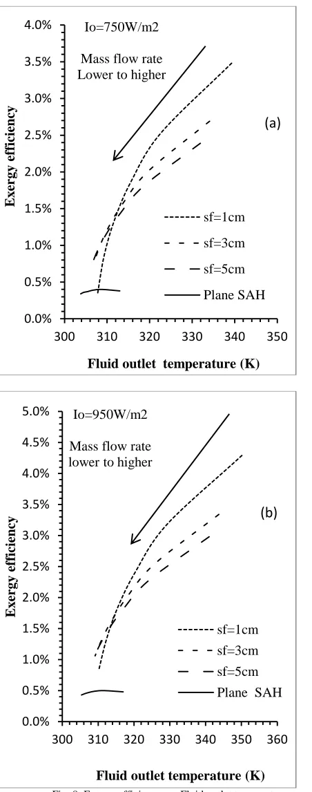
Fig. 8. Exergy efficiency vs. Fluid outlet temperature at different mass flow rate for various fin spacing (a) Io=750W/m2, (b)
Io=950W/m2.
Figs.8 (a) and (b) show effect of offset fin spacing on the exergy efficiency and outlet temperature at different mass
spacing (1cm) at lower mass flow rate of 0.01388 kg/s maintains the higher exergy efficiency and outlet temperature of flowing fluid. It is found that at lower mass flow rate of 0.01388 kg/s the variation of exergy for different fin spacing is higher and at higher mass flow rate of 0.0833 kg/s, the trend of variation is reversed. Further it is seen that the outlet temperature is almost same for all fins spacing at higher mass flow rate of air.
5. Conclusions
An analytical approach for thermal and exergy performances of offset finned solar air heater has been carried out. The most important findings of this study are summarized in the following:
1) The thermal efficiency increases with increase in mass flow rate and decrease in fin spacing, fin height, whereas the trend of exergy efficiency is reversed. The trend of variation of thermal and exergy efficiency is not the same.
2) The percentage enhancement in thermal efficiency increases with increase in mass flow rate whereas the exergy efficiency decreases.
3) At lower mass flow rate of 0.01388 kg/s the variation of exergy for different fin spacing is higher whereas at higher mass flow rate of 0.0833 kg/s, the trend of variation is reversed.
4) The outlet temperature is almost same for all fins spacing at higher mass flow rate of air.
5) Attaching offset fins below the absorber plate, lead to exergy efficiency increase compared to a plane solar air heater. The improvement in exergy efficiency is due to enhanced heat transfer area and also creation of more turbulence which results in higher heat energy gain. Also result reveals that at higher mass flow rate exergy efficiency decreases rapidly with increase in fin spacing.
REFERENCES
[1] Choudhury, C., Garg, H.P. Design analysis of corrugated and flat plate solar air heaters. Renew Energy 1991; 1:595–607.
[2] Choudhury, C., Garg, H.P., Prakash, J. Design studies of packed-bed solar air heaters. Energy Convers Manage 1993; 34(2):125– 138.
[3] Akpinar, E.K., Kocyig˘it, F. Experimental investigation of thermal performance of solar air heater having different obstacles on absorber plates. Int. Commun. Heat Mass Transfer 2010; 37:416– 421.
[4] Hachemi, A. Comparative study on the thermal performances of solar air heater collectors with selective absorber plate. Renew Energy 1999; 17:103–112.
[5] Yeh, H.M., Ho, C.D., Lin, C.Y. Effect of collector aspect ratio on the collector efficiency of upward type baffled solar air heaters. Energy Convers Manage 2000; 41:971–981.
[6] Zaid, A.A., Messaoudi, H., Abenne, A., Ray, M.L., Desmons, J.Y., Abed, B. Experimental study of thermal performance improvement of a solar air flat plate collector through the use of obstacles: application for the drying of „„yellow onion‟‟. Int J Energy Res
0.0% 0.5% 1.0% 1.5% 2.0% 2.5% 3.0% 3.5% 4.0%
300 310 320 330 340 350
E x er g y ef ficiency
Fluid outlet temperature (K) Io=750W/m2
Mass flow rate Lower to higher
sf=1cm sf=3cm sf=5cm Plane SAH
(a)
0.0% 0.5% 1.0% 1.5% 2.0% 2.5% 3.0% 3.5% 4.0% 4.5% 5.0%300 310 320 330 340 350 360
E x er g y ef ficiency
Fluid outlet temperature (K) Io=950W/m2
Mass flow rate lower to higher
sf=1cm
sf=3cm
sf=5cm
effective and exergy efficiencies. Renew Energy 2009; 34:465-476.
[9] Alta, D., Bilgili, E., Ertekin, C., Yaldiz, O. Experimental investigation of three different solar air heaters: energy and exergy analyses. Appl Energy 2010; 87:2953-2973.
[10] Singh, S., Chander, S., Saini, J.S. Exergy based analysis of solar air heater having discrete V-down rib roughness on absorber plate. Energy 2012; 37:749-758.
[11] Shah, M.K., Prasad, R.K. Exergy based performance evaluation of solar air heater with arc-shaped wire roughened absorber plate, Renewable Energy 2016; 96,233-243.
[12] Sabzpooshani, M., Mohammadi, K., Khorasanizadeh, H. Exergetic performance evaluation of a single pass baffled solar air Heater. Energy 2014; 64: 697-706.
[13] Manglik RM, Bergles A.E; Heat transfer and pressure drop correlation for the rectangular offset strip fin compact heat exchanger.Exp. Thermal fluid Sci.1995; 10(2):171-180.