F
Abstract— Conceptual design is the most critical stage of
any product design and development process. It is the stage where major design decisions are made with vague and imprecise information. Unfortunately, computer support tools at this stage are lagging behind compared to available CAD tools for later stage of design. Developing computer tool that can assist designers at the conceptual design stage can fill this gap and improve the design process. Towards this goal a conceptual design support tool for subsea processing equipment design (CDS Tsped) is developed integrating a systematic design approach with knowledge based system. Conceptual design knowledge for subsea process equipment have been collected and stored in the computer system. CDS Tsped supports the key features of conceptual design process such as functional modeling, concept generation and concept evaluation.
Index Term— conceptual design, functional design, knowledge based system, subsea processing.
I. INT RODUCT ION
Conceptualdesign is the most important and critical phase of any product design process. It is the stage where the product's fundamental features are determined, large proportion of cost of the product is committed [1, 2], and other major decisions are made with incomplete and imprecise information. Decisions made early at this stage have a significant impact on other aspects of a product‘s life cycle such as quality, cost, and manufacturability. It is usually difficult and even impossible to compensate a poorly conceived concept with good detail design process [2-5]. In designing a product, knowledge about the product increases as the design process progress from conceptual design to the detail design phase, but the impact of decision declines because decisions made at the earlier stages become constraints for the later stage.
Now days, there are several commercial CAD tools available in the market to assist designers in the design of
T his work was supported by Universiti T eknologi Petronas (UT P) graduate assistantship scheme.
D. E. Woldemichael is PhD candidate in Mechanical Engineering programme, Universiti T eknologi Petronas (UT P), Bandar Seri Iskandar, 31750 T ronoh, Perak, Malaysia. (phone: +60175655753; e
-mail: [email protected]).
F. M. Hashim is Associate Professor of Mechanical Engineering in Universiti T eknologi Petronas (UT P), Bandar Seri Iskandar, 31750
T ronoh, Perak, Malaysia. (e-mail: [email protected] ).
mechanical products. These tools are successful in dealing with geometric information rather than aspects of the conceptual design process, such as function modeling, concept generation, and evaluation, which are important during the early phase of design. Hence, the strength and use of the currently available CAD tools lies more at the detail design phase than the conceptual phase [6]. One of the reasons for this is that, the knowledge of design requirements and constraints during this early phase is usually imprecise and incomplete making it difficult to implement [3]. The other reason for the conventional CAD system not to support conceptual design is that, they do not have built in intelligent system to perform functional reasoning, and lacks the knowledge to draw conclusions from inadequate and approximate information available at this stage [7]. Hence, currently there is no known commercial computer aided conceptual design tool that can be used to design all products in the market. However, there are a number of prototype tools developed in research centers such as MODESSA (MOrphological DESign Support Aid) [8], Schemebuilder [9], web based morphological chart [10], AIDA (Artificial Intelligence supported Design of Aircraft), [11], EFDEX (Engineering Functional Design Expert) [7], 2nd-CAD [12], IDEA-INSPIRE [13], and Concept Generator [14]. These tools use varieties of approaches for representation and categorization of knowledge. Some of them are limited to specific domain. For example, AIDA is for aircraft design, and, 2nd-CAD is for electromechanical Systems. Some of these tools like EFDEX, IDEA-INSPIRE, and Concept Generator are designed for generating concepts from a database. Others like Schemebuilder, MODESSA and web based morphological chart covers the entire conceptual design process including concept evaluation.
Design process s tarts by identifying key customer needs. The customer specifies his/her need in terms of desired function of the product. The customer needs are sometimes presented vaguely. Thus the role of the designer is to come up with products that satisfy the desired functions. This is initially done during the conceptual design process, where the aim is transformation of abstract functional description of design into a conceptual (physical) description . Hence, the upstream design activity is function oriented, and th e process is known as functional design. According to Tor et al [15], functional design is an approach for designing CAD software that incorporates the representation of functional information, as well as structural information, and its aim is to
Development of Conceptual Design Support Tool
for Subsea Process Equipment Design
provide computer tools to link design functions with the physical embodiments used to realize the functions.
In this paper we propose a new conceptual design process model which integrates systematic design approach [5] with knowledge bases system and develop a conceptual design support tool for subsea process equipmen t design (CDSTsped). The tool is not meant to fully automate the conceptual design process and substitute human designer. However, it is supposed to assist designers by handling some of the monotonous activities giving more time for the designer to concentrate on the creativity. The design knowledge in the computer support tool is developed based on design reuse philosophy. Design reuse plays central role in the conceptual design stage especially in concept generation process. Conceptual design knowledge can be obtained from experts or extracted from existing products and saved in the design knowledge base. To archive design knowledge in a computer, the use of standard method of representing mechanical functions and alternative concepts is important. This fosters reuse of the design knowledge for other similar problems in the future. The computer support tool will be used in generating alternative concepts for given functions, creating morphology chart, combining compatible alternative concepts, and evaluate the concept variants. In general, the tool will assist human designer in the conceptual design process:
by providing design knowledge from past experiences; and
handling some of the monotonous and time consuming tasks which gives the designer more time to concentrate on the creative part of design where humans are better than computers .
The production rules in the knowledge-based system are generic to be used for any mechanical conceptual design process. However, the domain of application for the current research is concerned with conceptual design knowledge of subsea process equipment design in oil and gas industry. There is no known conceptual design support tool so far to address this domain. In recent years because of high global oil demand, depletion of old onshore fields and technological advancement, operators are moving to deepwater field development. The produced fluid from subsea wells which is mostly a multiphase mixture of oil, water and gas is transported to a platform or floating production sto rage and offloading (FPSO) deck located many kilometers away for processing. Because of back pressure imposed by production risers and long tie-backs there is a growing interest in processing the produced fluids on the seafloor (i.e., subsea processing) [16]. Subsea processing mainly comprises of subsea separation and boosting. Separating fluids on the sea floor will avoid lifting large volumes of water to the surface for processing and disposal. Furthermore, subsea processing provides lesser susceptibility to hydrate formation since all the processing to final saleable crude can be done at the seabed. In general subsea processin g provides reduced load requirement on the platform, and
improved recoveries and greater efficiencies [17]. However, subsea processing is an emerging technology which has not yet been fully utilized and there is also resistance from operators to use this new approach.
The remainder of this paper is organized as follows. Section II presents detail description of the proposed conceptual design process model. Section III presents the implementation of the proposed model into a computer program. Section IV describes the main features of the developed tool (CDSTsped) and the conclusion part is presented in Section V.
II. CONCEPT UAL DESIGN PROCESS MODEL
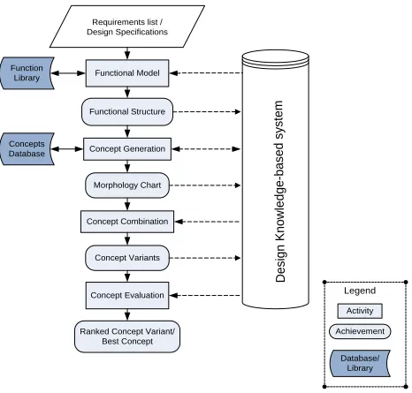
Conceptual design process can be considered as transformation of design specification which is given as requirement list into one or more concepts that can satisfy these requirements for further development. Careful and extensive exploration of the design space helps not to overlook better design solutions. This is because in most cases there is more than one solution that can satisfy the given requirements. After thoroughly examining the way humans perform conceptual design following a systematic design approach, a conceptual design process model shown in (Fig. 1), is proposed. This model integrates the systematic design approach [5] with knowledge based system and consists of series of activities and achievements. The activities (i.e., functional modeling, concept generation, concept combination, and concept evaluation) are done by the designer‘s knowledge and/or the design knowledge-base system. The achievements from a given activity are displayed to the user and given as input to the design knowledge-base system to perform the next activity. The dotted lines in Fig 1,
indicate the information flow between the
activities/achievements and the design knowledge-based system.
Function Library
Concepts Database
Functional Model
Functional Structure
Concept Generation
Morphology Chart
Concept Combination
Concept Variants
Concept Evaluation
Ranked Concept Variant/ Best Concept
D
e
s
ig
n
K
n
o
w
le
d
g
e
-b
a
s
e
d
s
y
s
te
m
Requirements list / Design Specifications
Achievement Activity
Database/ Library Legend
activity in the proposed model and its implementation in developing CDSTsped are presented next.
A. 5BFunctional model
Functional modeling is a process of analyzing the requirement list or design specification to come up with the overall function of the design problem and decomposing this into discrete easily solvable subfunctions to establish functional structure. Form follows functions, and every product has some reason for its existence wh ich is its function. Function plays central role in conceptual design as geometry does in later stages of design . Functions are represented using linguistic approach as verb + noun together with additional information such as input and output flows. A standard vocabulary of functions is also required for repeatable design process. A reconciled functional basis proposed by Hirtz et al[18], is adopted in this research to develop library of mechanical functions. In the reconciled functional basis, functions are classified into eight primary classes and forty five secondary and tertiary class es of action verbs. There are three basic (primary) classes of flows: material, energy and signal, which also have forty two secondary and tertiary flows. Function can be represented by combining the primary, secondary or tertiary classes of functions as ‗verb‘ and flows as ‗noun‘ in functional basis.
For each product to be designed by CDSTsped, the functional modeling in which the overall function is decomposed into subfunctions is included in the system by analyzing existing product and from experts . The functional modeling can also be modified to include new functionality by the designer. All the subfunctions in the functional modeling are represented in terms the functions in the function library.
B. Concept Generation
The concept generation process is done using predefined domain independent production rules in the knowledge base by searching the alternative concepts database. For this purpose, an alternative concepts database for subsea process equipments have been built by collecting concepts from handbooks, patents, manufacturer‘s catalogue and personal experience. Two types of rules are used for concept generation. The first one is mapping rule, where for all subfunctions in the working memory, the system searches for concepts who‘s primary or secondary function matches with the subfunction. If there are alternative concepts in the concept database, the subfunction and all the alternative concepts will be included in the morphology chart and asserted to the working memory. If there is no alternative concept for one or more of the subfunctions in the database, the second type of rule will be fired (executed). In this case the user will be asked to perform concept generation manually and give as input alternative concepts that will be saved in the data base for future use. Finally, the subfunctions and their corresponding alternative concepts are displayed on the morphology chart.
C. Concept combination
After alternative concepts are generated for each subfunction in the functional structure, the overall fu nction is achieved by combining the concepts. Predefined domain independent production rules are used to create the concept variants. In order to reduce the combinatorial explosion, the designer evaluates the generated concepts for each subfunctions and eliminate from the morphology chart before combining the concepts. Furthermore, for single flow non branching functional structures, flow compatibility criterion is included. In general there are two types of production rules in the knowledge base to perform concept combination process:
1. General rule to create theoretically possible concept variants. In this case, the concept variants are created by taking one concept at a time for each subfunction in the morphology chart.
2. Flow constrained rule to create flow compatible concept variants. The synthesis process is the same as the general rule, but flow compatibility constraint is added. Concept variants are considered compatible, if and only if the output flow of the preceding concept is the same as the input flow of the succeeding concept in the morphology chart.
Since the number of subfunction for different products is not the same, the knowledge base contains production rules for each possible case. The combined concept variants are displayed both textually and schematically showing all the component concepts that make up the concept variant.
D. Concept evaluation
The concept evaluation process will be done in three sequential steps. First evaluate using absolute comparison method where concepts are directly compared with some set of requirements. This results in eliminating some of the infeasible concept variants. Next the remaining concept variants will be evaluated using concept screening method iteratively taking competitive product or one of the concept variants as a datum. If the competitive product is to be taken as datum concept, it should be reduced to the same level of abstraction as other concept variants. This process will reduce further the number of concept variants and the remaining once will be finally evaluated using weighted decision matrix method. The relative weight of the selection criteria may be assigned either by direct assignment or pair wise comparison using analytical hierarchy process method. The output of this evaluation process will be ranked concept variants, from which one or more concepts will be selected for further development or combining some of the concept variants to obtain better performance concept variants and repeat the conceptual design process.
stored knowledge to solve problems in a specific domain [19]. The three main architectural components of a knowledge-based system are: 1) knowledge base which contain the domain knowledge, 2) inference engine (controlling mechanism), and 3) interface to the outside world (user interface). A knowledge acquisition module can also be included to these main components to facilitate addition of new knowledge, both during the program development and in the program‘s lifetime. The knowledge base and the inference engine are implemented using CLIPS 6.3 (C Language Integrated Production System). CLIPS is an expert system shell, which was developed by the Software Technology Branch (STB), NASA/Lyndon B. Johnson Space Center. CLIPS allow hybrid knowledge representation including rule based, user defined functions and object-oriented programming in one [20]. To incorporate graphical knowledge representation and develop a user-friendly graphical user interface (GUI), wxPython is used. wxPython is a cross -platform wrapper for the GUI application programming interface (API) wxWidgets for the Python programming language. A module known as PyCLIPS does the interface between Python and CLIPS. CLIPS, Python, wxPython and PyCLIPS are all public domain open source software. Fig. 2 shows the architectural components of the knowledge-based system and the programming environments used to implement.
Fig. 2. Architectural components of the knowledge based system and programming environments used to implement in CDST sped
Based on the methodology described in the previous section, a prototype tool i.e., CDSTsped is developed using these programming environments . The flow chart of CDSTsped is shown in Fig.3. A user friendly GUI is developed where the user can easily explore the design information and perform conceptual design on windows program using push buttons, choice items, and menu bars according to the flow diagram.
IV. 3FEAT URES OF CDSTSPED
Currently, CDSTsped consists of conceptual design knowledge of subsea process equipments specifically
separators and boosters (pumps). Concepts about subsea multiphase technologies currently available such as twin screw pumps, progressive cavity pumps (PCP), piston pumps, and helicon-axial rotor dynamic pumps are included. Next, the steps in conducting conceptual design process and features of CDSTsped are discussed by taking sample screenshots.
Start
Select product to be designed
Separator Pump
Search for alternative concepts Two-phase Three-phase
Display Morphology Chart
Display Subfunctions
Select type of flow Select type pump
Displacement Kinetic/Dynamic
Select how energy is added to the system
Rotary Positive Displacement
Combine concepts
Theoretically possible concepts
Concept variants schematic Flow compatible concepts
Concept variants (textual)
Concept evaluation
Absolute comparison Evaluation Criteria
Use predefined criteria Enter new criteria
Assign weight for each criteria
Direct assignment Pair wise comparison
using AHP evaluate
Select datum and evaluate
evaluate
Ranked Concept variants Selected Concept variants
Selected Concept variants
Weighted decision matrix Concept Screening method
Repeat?
No Yes
No Evaluate with other method? Yes
Fig. 3. Flow chart of CDST sped
A. 9BInitiating CDSTsped
displayed. For instance selecting the pump option brings the pump design window (Fig. 5), where the user selects the type of pump to be designed. Depending on the selection, the functional modeling which includes the overall function and subfunctions for that particular product is displayed. For brevity only few sample windows are shown here.
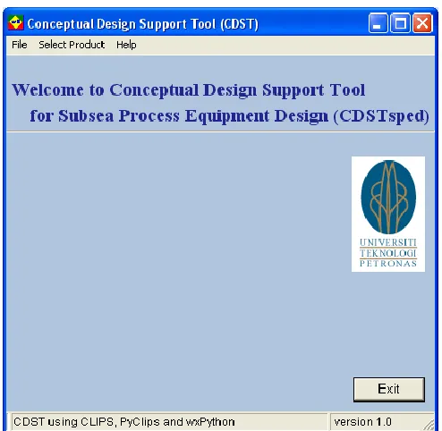
Fig. 4. Screenshot of CDST sped initial window
Fig. 5. Screenshot of pump type selector window
B. 10BFunctional modeling and concept generation
Function modeling is where the problem is described in terms of subfunctions. For each subfunction in the functional modeling the system searches its database for alternative concepts satisfying those subfunctions in the concept generation stage. For example the functional model of two phase separator design window is shown in Fig 6. The generated concepts for these subfunctions are shown in the morphology chart (Fig.7)
Fig. 6. Subfunctions for two phase separator
Fig. 7. Excerpt from morphology chart for two phase separator
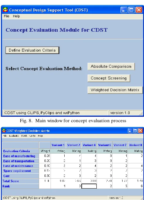
C. 1Concept combination and evaluation
system will calculate the total score and rank the concept variants based on the rating. Among these methods, sample screenshot of weighted decision matrix is shown in Fig 9.
Fig. 8. Main window for concept evaluation process
Fig. 9. Screenshot of weighted decision matrix
V. CONCLUSIONS
Because of lack of computer assistant tools and the nature of the design problem, most of the time conceptual design is done manually by experienced designers. Developing computer assistant tool by capturing the knowledge of the expertise is one of the contributions of the work presented in this paper. The developed design support tool can be used to reduce the product design time since most of the repetitive and time consuming tasks are handled by the tool, leaving the designer to concentrate on creative part of design work where humans are better than computers. CDSTsped can also be used as the design knowledge management system, by storing the design knowledge of experienced designers for future use. For each product designed in given company similar tool can be developed with the methodology proposed in this paper. The importance of such tools is inevitable with the current high turnover of experienced designers looking for better payment and retirement. In addition, it can be used to train novice designers in industry and as design teaching aid in academia.
REFERENCES
[1] D. B. Sieger and R. E. Salmi, "Knowledge representation tool for conceptual development of product designs," in 1997 IEEE
International Conference on System s, Man, and Cybernetics,
1997, pp. 1936-1941.
[2] W. Hsu and B. Liu, "Conceptual design: Issues and challenges,"
Com puter-Aided Design, vol. 32, pp. 849-850, 2000.
[3] W. Hsu and I. M. Y. Woon, "Current research in the conceptual design of mechanical products," Com puter-Aided Design, vol. 30, pp. 377-389, 1998.
[4] L. Wang, W. Shen, H. Xie, J. Neelamkavil, and A. Pardasani, "Collaborative conceptual design - state of the art and future trends," Com puter-Aided Design, vol. 34, pp. 981-996, 2002. [5] G. Pahl, W. Beitz, J. Feldhusen, and K.-H. Grote, Engineering
design : A system atic approach, 3rd ed.: Springer, 2007.
[6] B. F. Robertson and D. F. Radcliffe, "Impact of CAD tools on creative problem solving in engineering design," Com puter-Aided
Design, vol. 41, pp. 136-146, 2009.
[7] W. Y. Zhang, S. B. T or, G. A. Britton, and Y. -M. Deng, "EFDEX: A knowledge-based expert system for functional design of engineering systems," Engineering with Com puters, vol. 17, pp. 339-353, 2001.
[8] T . Kersten, "MODESSA: A computer based conceptual design support system," in AI system support for conceptual design,
Lancaster International workshop on engineering design,
Lancaster, 1995, pp. 241-259.
[9] R. H. Bracewell and J. E. E. Sharpe, "Functional descriptions used in computer support for qualitative scheme generation — schemebuilder," Artificial Intelligence for Engineering Design,
Analysis and Manufacturing, vol. 10, pp. 333-346, 1996.
[10] G. Q. Huang and K. L. Mak, "Web-based morphological charts for concept design in collaborative product development,"
Journal of Intelligent Manufacturing, vol. 10, pp. 267-278,
1999.
[11] D. Rentema and E. Jansen, "An AI tool for conceptual design of complex products," in Design Research in the Netherlands 2000, Eindhoven University of T echnology, 2000, pp. 119 -131. [12] N. Vargas-Hernandez and J. J. Shah, "2nd-CAD: A tool for
conceptual systems design in electromechanical domain," Journal
of Com puting and Inform ation Science in Engineering, vol. 4,
pp. 28-36, 2004.
[13] A. Chakrabarti, P. Sarkar, B. Leelavathamma, and B. S. Nataraju, "A functional representation for aiding biomimetic and art ificial inspiration of new ideas," Artificial Intelligence for Engineering
Design, Analysis and Manufacturing, vol. 19, pp. 113-132,
2005.
[14] C. R. Bryant, D. A. McAdams, R. B. Stone, T . Kurtoglu, and M. I. Campbell, "A computational technique for concep t generation," in IDETC/CIE 2005, Long Beach, California USA, 2005, pp. 267-276.
[15] S.B. T or, G.A. Britton, a. M. Chandrashekar, and N. K. Wee, "Functional design," in Integrated product and process
developm ent: Methods, tools, and technologies, John M Usher,
Utpal Roy, and H. R. Parsael, Eds. New York: John Willey &Sons, Inc., 1998.
[16] S. L. Scott, D. Devegowda, and A. M. Martin, "Assessment of subsea production & well systems," Department of Petroleum Engineering, T exas A&M University, Final Report Submitted to the U.S. Department of Interior – Minerals Management Service (MMS), T echnology Assessment & Research (T A&R) Program 2004.
[17] W. C. Lyons and G. J. Plisga, "Standard handbook of petroleum & natural gas engineering," 2nd ed: Gulf Professional P ublishing, 2005.
[18] J. Hirtz, R. Stone, D. McAdams, S. Szykman, and K. Wood, "A functional basis for engineering design: Reconciling and evolving previous efforts," Research in Engineering Design, vol. 13, pp. 65-82, 2002.
[19] A. A. Hopgood, Intelligent system s for engineers and scientists, 2nd ed.: CRC Press, 2001.
[20] J. C. Giarratano and G. Riley, Expert system s : Principles and