Automation, Control and Intelligent Systems
2013; 1(4): 85-89Published online August 10, 2013 (http://www.sciencepublishinggroup.com/j/acis) doi: 10.11648/j.acis.20130104.11
Load frequency control for interconnected power system
using different controllers
Atul Ikhe
P. G. Department, College of Engineering Ambajogai, Dist. Beed, Maharashtra, India
Email address:
[email protected](A. Ikhe)
To cite this article:
Atul Ikhe. Load Frequency Control for Interconnected Power System Using Different Controllers. Automation, Control and Intelligent Systems. Vol. 1, No. 4, 2013, pp. 85-89. doi:10.11648/j.acis.20130104.11
Abstract:
This paper explores the potential of using soft computing methodologies in controllers and their advantages over conventional methods. PID controller, being the most widely used controller in industrial applications, needs efficient methods to control the different parameters of the plant. As reported by several researchers, the conventional approach of PID controller is not very efficient due to the presence of non-linearity in the system of the plant. Also, the output of the conventional PID system has a quite high overshoot and settling time. The main focus of this work is on the controller to obtain good output frequency responses. The tuning of PID controller is necessary to get an output with better dynamic and static performance. The application of PID controller imparts it the ability of tuning itself automatically in an on-line process while the application. The output response of PID-tuning is compared with I, PI and conventional PID controller and found reasonably good over these conventional controllers.Keywords
: Conventional Controller, Interconnected Power System, Load Frequency Control (LFC), PID Tuning, Tie-Line1. Introduction
The problem of controlling the real power output of generating units in response to changes in system frequency and tie-line power interchange within specified limits is known as load frequency control (LFC) [1]. The Objectives of LFC are to provide zero steady-state errors of frequency and tie-line exchange variations, high damping of frequency oscillations and decreasing overshoot of the disturbance so that the system is not too far from the stability [2]. The interconnected power system is typically divided into control areas, with each consisting of one or more power utility companies. Sufficient supply for generation of each connected area to meet the load demand of its customers.
The above mentioned objectives are carried successfully in previous works by different authors using PI and PID controllers [4] & [5].
In this paper PID-tune controller is used for better frequency responses. This type of controller is used in power system so reducing the steady state error. System load is never steady using this controller these can be controlled. When uncontrolled case more oscillation, negative overshoot be observed but while comparing to conventional type controller PID and propose work result gives better performances of dynamic responses.
2. PID Controller
There are many types of controller such like proportional, integral, derivative and combinational of these (PI, PID).
2.1. PID Controller
The block diagram of Proportional Integrative Deri vative (PID) controller is shown in Fig.1
Figure 1: Block diagram of a PID controller.
& [9].
y(t)=
Kpe
(t
)
+Ki
e
τ
d
τ
t
)
(
0
∫
+e
(t
)
dt
d
Kd
(1)Where y (t) is the controller output and u (t) is the error signal. Kp, Ki and Kd are proportional, integral and derivative
gains of the controller. The limitation conventional PI and PID controllers are slow and lack of efficiency in handling system non-linearity. Generally these gains are tuned with help of different optimizing methods such as Ziegler Nicholas method, Genetic algorithm, etc., The optimum gain values once obtained is fixed for the controller. But in the case deregulated environment large uncertainties in load and change in system parameters is often occurred. The optimum controller gains calculated previously may not be suitable for new conditions, which results in improper working of controller. So to avoid such situations the gains must be tuned continuously.
The tuning parameters are
2.1.1. Proportional Gain (Kp)
Larger values typically mean faster response since the larger the error, the larger the Proportional term compensation. An excessively large proportional gain will lead to process instability and oscillation.
2.1.2. Integral Gain (Ki)
Larger values imply steady state errors are eliminated more quickly. The trade-off is larger overshoot: any negative error integrated during transient response must be integrated away by positive error before we reach steady state.
2.1.3. Derivative Gain (Kd)
Larger values decrease overshoot, but slows down transient response and may lead to instability due to signal noise amplification in the differentiation of the error.
2.2. Advantages of PID Controller
They can perform poorly in some applications. PID controllers, when used alone, can give poor performance when the PID loop gains must be reduced so that the control system does not overshoot, oscillate or hunt about the control set point value. A problem with the Derivative term is that small amounts of measurement or process noise can cause large amounts of change in the output.
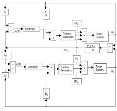
3. Model of Two Area Power System
Each area is assumed to have only one equivalent Generator and is equipped with governor- turbine system. They are the control signals from the controllers A two area model is adapted in the work is shown in Figure.2 [2] & [11].
Figure 2: Block diagram of two area power system.
The terms showed in the Figure 2 are termed given below: fi :Nominal system frequency of ith area. [HZ]
∆ f I :Incremental frequency deviation of ith area. [HZ pu] Tsi : Speed governor time constant of i th area [sec.] Kgi : Gain of speed governor of i th area
Ri :Governor Speed regulation of the of ith area [ Z H
/pu.MW]
Tti : Governor Speed regulation of the of ith area [ Z H
/pu.MW]
Kti : Gain of turbine of ith area
Kpi :Gain of power system (generator load) of i th area. [ Z H /pu.MW]
Kpi = 1/D
Tpi Gain of power system (generator load) of i th area. [ Z H /pu.MW]
Tpi = 2Hi /Difi
Hi : Inertia constant of i th area . [MW-sec/MVA]
∆PGi : Incremental generator power output change of ith area .[pu MW]
∆Pti : Incremental turbine power output change of i th area. [pu MW]
Ki : Gain of controller of ith area.
The plant for a power system with a non-reheated turbine consists of three parts:
• Governor with dynamics:
G
g(s)=1
1
+
TGs
. (2)• Turbine with dynamics:
Gt(s)=
1
1
+
TTs
. (3)• Load and machine with dynamics:
Gp(s)=
1
+
TPs
Kp
. (4)
Automation, Control and Intelligent Systems 2013; 1(4): 85-89 87
GpGtGg
P
~
=
=)
1
)(
1
)(
1
(
TPs
+
TTs
+
TGs
+
Kp
. (5)
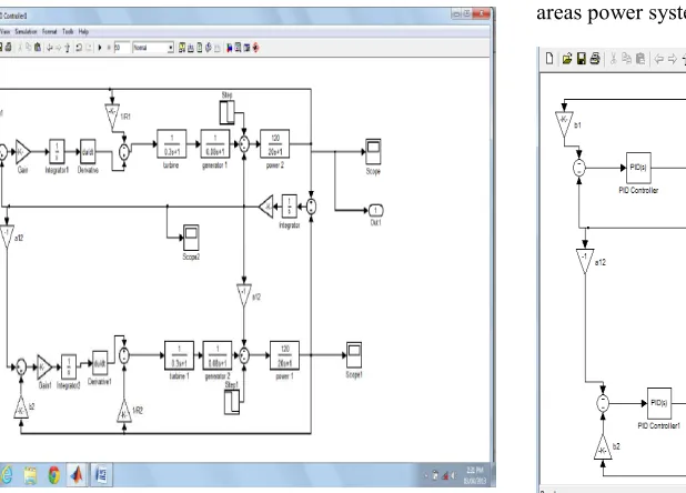
4. Matlab Simulink Model
4.1. Power system Model Using Different Controllers
In two area system, two single area systems are interconnected via tie-line. Inter connections established increases the overall system reliability. Even if some generating units in one area fail, the generating units in the other area can compensate to meet the load demand. The basic block diagram of five area interconnected power system is shown in Fig.2. A conventional integral controller is used on a power system model. The PID controller improves steady state error simultaneously allowing a transient response with little or no overshoot. As long as error remains, the integral output will increase causing the speed changer position, attains a constant value only when the frequency error has reduced to zero. The SIMULINK model of a two area interconnected power system using PID controller is shown in Figure 3[6].
Figure 3: Simulink model of two area power system using PID controller.
The output response is shown in Fig.4,which having the
comparison results between simple integral(I), proportional integral (PI) ,Proportional integral derivative (PID).
The output frequency response using PID is better than I and PI.
Figure 4: Output frequency response using different controller.
The gain value of different types of controller using in two areas power system is given in Table 1.
Figure 5: Simulink model of two area power system using PID tuning controller.
Table 1: Different values of gain for controllers [citation].
Kp Ki Kd
Settling time (sec.)
Controller Area1 Area2 Area1 Area 2 Area 1 Area 2
I - - 0.2742 0.4680 - - 35
PI 0.1109 0.0121 0.2742 0.2019 - - 25
PID 0.1109 0.0121 0.2742 0.2019 0.1110 0.003 10
It shows that for different controllers getting different settling time value. The settling time of PID controller is less
4.2. Model of PID Tuning
The gain value of controller is automatically fixed when we select PID tuning controller. The MATLAB Simulink diagram is shown in Figure 5.
The output response of PID tuning method for area1, area 2 and Tie-line is shown in Figure 6(a), 6(b),6(c) respectively.
Figure 6(a): Output response of area 1.
Figure 6(b): Output response of area 2.
Figure 6(c): Output response of tie-line of power system.
For better dynamic responses using PID tuning method, we reduce settling time, oscillation. The response of power
system also varies according to rated power capacity of any system.
5. Conclusions
A tuning of PID controller used for load frequency controller of two area interconnected power system has been presented. It can be implemented in four area power system and controlled by using advanced controller systems. The system performance was observed on the basis of dynamic parameters i.e. settling time, overshoot and undershoot. The system performance characteristics reveals that the performance of PID tuning method better than other controllers. As a further study, the proposed method can be applied to multi area power system load frequency control (ALFC) and also optimum values can be obtained by Fuzzy Logic Controller (FLC), Genetic Algorithm and Neural networks.
References
[1] Wen Tan, “Unified tuning of PID load frequency controller for power system via IMC”,IEEE Trans. Power Systems, vol. 25, no. 1, pp. 341-350, 2010.
[2] G. Raj Goutham,Dr. B. Subramanyam, “IMC Tuning of PID Load Frequency Controllerand Comparing Different Configurations for Two Area Power System”,Internationa lJournal of Engineering Research and Applications, Vol. 2, Issue 3, May-Jun 2012,pp.1144-1150.
[3] Emre Ozkop, Ismail H. Altas, Adel M. Sharaf, “Load Frequency Control in Four Area Power Systems Using Fuzzy Logic PI Controller”,16thNational Power Systems Conference, 15th-17th Dec., 2010.
[4] K. P. Singh Parmar, S. Majhi, D. P. Kothari, “Optimal Load Frequency Control of an Interconnected Power System”, MIT International Journal of Electrical and Instrumentation Engineering, vol. 1, No. 1, pp 1-5, Jan 2011.
[5] Mohammad Soroush Soheilirad, Mohammad Ali Jan Ghasab, Seyed mohamm-dhossein Sefidgar, Aminmohammad Saberian,“Tuning of PID Controller for Multi AreaLoad Frequency Controlby Using Imperialist Competitive Algorithm”, J. Basic. Appl. Sci.Res., 2(4)3461-3469, 2012.
[6] Akanksha Sharma, K.P. Singh Parmar and Dr. S.K. Gupta, “Automatic Generation Controlof Multi Area Power System using ANN Controller”, International Journal of ComputerScience and Telecommunications [vol. 3, Issue 3, March 2012]
[7] S.Ganapathy, S.Velusami, “Design of MOEA based Decentralized Load-Frequency Controllers for Interconnected Power Systems with AC-DC Parallel Tie-lines”, International Journal of Recent Trends in Engineering, Vol 2, No. 5, November 2009.
Automation, Control and Intelligent Systems 2013; 1(4): 85-89 89
[9] K.RamaSudha,V.S.Vakula, R.VijayaShanthi, “PSO based Design of Robust Controller for Two Area Load Frequency Control with Non linarites”, International Journal of Engineering Science and Technology, Vol. 2(5), 2010, 1311-1324
[10] G.Karthikeyan, S.Ramya, Dr. S.Chandrasekar, “Load Frequency Control for Three Area System with Time Delays Using Fuzzy Logic Controller”, International Journal of Engineering Science & Advanced Technology, ISSN: 2250–3676 Volume-2, Issue-3, 612 – 618.
[11] Kanika Wadhwa, Sourav Choubey, Pardeep Nain, “Study of Automatic Generation Control Of two area thermal-thermal system with GRC and without GRC”, First National
conference on Power System Engineering (PSEC’12) Paper code PS1015.
[12] K. S. S. Ramakrishna1,” Automatic generation control of interconnected power system with diverse sources of power generation,” International Journal of Engineering, Science and Technology, Vol. 2, No. 5, 2010, pp. 51-65