Themed Section: Engineering and Technology
A Detailed Study on the Analysis of Large Span Cantilever Space
Structures by Using STAAD-Pro
Gudisi Obaiah1, Syed Rizwan2, Dr. C. Rama Chandrudu3
*1M.Tech Student, St.Mark Educational Institution Society group of institutions, Anantapur, Andhra Pradesh,
India
*2,& *3Assistant Professor and Professor, Civil Engineering Department, Chiranjeevi Reddy Institute of
Engineering & Technology, Anantapur, Andhra Pradesh, India ABSTRACT
Study of Space structures, especially skeletal frameworks, when exposed provides an architecturally pleasing appearance. They possess great rigidity and stiffness for a given span/depth ratio and hence are able to resist large concentrated and unsymmetrical loading. They have built –in reserve strength enabling the structures to take over loading. Space structures, especially double layer grid even when damaged, never collapse rapidly. This property is of great importance in the case of fire, earth quake, explosion or terrorist attack. Due to their rigidity, they allow greater flexibility in layout and positioning columns. It is possible for some columns to be removed and have their positions changed without damaging the structural the integrity of the frame work. The shortage and increasing cost of qualified labour has favored the adoption of prefabricated and industrials forms of construction. Space structures can be assembled from simple, prefabricated units of standard size and shape, which can be mass produced in the factory and assembled easily and rapidly at site by semiskilled labour. The small size of components greatly simplifies handling, transportation and erection of these structures. The network configuration of space structures accounts for its lightness. Large columns free areas are usually required for industrial buildings, sports stadiums swimming pools, exhibition halls theatres and assembly rooms. Space structures are ideally suited for such requirements; for very large column free areas they are very economical and provide the only solution. Even with non-uniform stress conditions, member sizes and joint details often fall into a few groupings for a particular structure, permitting the advantages use of factory production methods to reduce fabrication cost. In multilayer space structures, lights, air conditioning ducts and other facilities can be kept inside the roof elements, thus giving a very neat appearance. Presently in this thesis, analysis and Design of different types of sections such as tube, pipe, angle for cantilever space structure model has been done using STAAD PRO software and the results have been compared to provide which section is economy and the conclusions are presented.
Keywords : Cantilever, Earthquake, Fabrication, Space structure, STAAD-PRO
I.
INTRODUCTIONDefinition of space structure
A space structure is a structural system in the form of a three-dimensional assembly of elements (as opposed to a continuous surface), resisting loads which can be applied at a point, inclined at any angle to the surface
of the structure and acting in any direction. Rolled, extruded or fabricated sections comprise the member elements.
Historical Development
these structures have been built in one form or another. Hundreds of publications concerning various aspects of their analysis, design and construction have been written and the technology associated with these structures is highly developed in many areas. Some of the timber structures of antiquity could be cited as forerunners of modern space structures. Since structures of the middle ages were mostly of the solid masonry type, with timber construction primarily taking the form of frames or planar trusses, little progress was made in the technology of space frames beyond that of timber domes. Most of the interesting developments of space frames took place after the young Leigpzig engineer, August Foppl wrote his first book on space structures under title “Theorie des Fachwerks” (Theory of Lattice systems) in 1880. Among the few who appreciated Foppl‟s theories of calculations of space frames was Gustave Eiffel who built the viewing tower, named after him, for the Paris World Exhibition in 1889. This is the first space structures built in steel with its calculations based on three-dimensional geometry. The tower was originally meant to be dismantled after the end of the exhibition, but turned out so well that it stands even today, not only as the symbol of Paris, but also as a monument to the genius of its designer. The bridge over the Firth of Forth at Queen ferry was also erected in the years 1852-1890 and with this constructions started the transition from the place to the space frame.
II.
TYPES OF SPACE STRUCTURES Skeleton (braced) frame works ;
Stressed skin systems ;
Suspended (cable or membrane) structures.
Of the above three types of structures, the skeleton frame works are more popular. These types of frames are also called latticed structures or space frames or reticulated structures .the overall shape of the surface and the pattern of the individual members of these
structures may greatly affect their architectural appearance. Since these innumerable possible combinations and variations, many structures have been Built. For reasons of utility and economy, majority of these structures follow regular geometric forms and can be categorized as structures having Positive Gaussian (synclastic) curvature (eg.Domes). Negative Gaussian (anticlastic) curvature (e.g., Hyperbolic parabola). Zero Gaussian curvature (e.g., grids). Braced barrel vaults are special types of skeletal structures having single curvature and zero Gaussian curvature .stressed skin folded plates, stressed skin domes and barrel vaults are typical examples of stressed skin systems. The cable roofs belong to the suspended structures.
III.
METHODS AND MATERIALMaterials used in space frames:
Timber:
The main problem in applying timber to space frames constructions is one of the connections between timber members in several planes.
Steel:
Steel is mostly frequently used in space frame construction and is an ideal material for such frame. Steel space frames may be constructed of cold-rolled sections, angles or tubes riveted , bolted or welded together or to suitably shaped gusset plates or connectors .tubes are much suitable since they may be more easily jointed at an angle, and due to their better performance in compression they will produce lighter structures over large spans.
Aluminum:
extruded sections. Aluminum sheets are used in stressed skin structures as load bearing elements.
Concrete:
The development of precasting and prestressing techniques has made possible the use of concrete members of comparatively light weight and small cross sectional area in the construction of space frames. These concrete members may be connected together with site bolting and grouting.
Plastics:
The stressed skin space grids and domes make possible the use of materials like plastics and aluminum which have very low young‟s modulus .plastics are mainly used for covering the space frames.
IV.
LITERATURE REVIEW:Most of the interesting developments of space frames took place after the young Leipzig Engineer, August Foppl wrote his first book on Space structures under the title, „Theorie des Fachwerks‟ (Theory of Lattice systems) in 1880. Among the few who appreciated Foppl‟s theories of calculations of space frames was Gustavo Eiffel who built the viewing tower, named after him, for the Paris World Exhibition of 1889. This is the first space structure built in steel with its calculations based on three-dimensional geometry. The tower was originally meant to be dismantled after the end of the exhibition, but turned out so well that it stands even today, not only as the symbol of Paris, but also as a monument to the genius of its designer. The bridge over the Firth of Forth at Queen ferry was also erected in the years 1852-1890 and with this construction started the transition from the plane to the space frame.
V.
SCOPE OF THE PROJECTClassification of the space structure adopted for study: The basic staad model of the space frame has prepared
as large span cantilever space frame structure of span 20mts on both longitudinally & latitudinal directions, it is supported with eight columns (supports) of „I‟section provided as five columns in one row and other three columns in another row for support to the structure, the same basic frame model has been studied using different sections (pipe, square tube and angular sections) and using different parameters to know the section, which is more safe and economical among the three different sections adopted for study.
VI.
DESCRIPTION OF THE MODEL:Types of sections used for analysis of frame are circular pipe, square tube and angular sections. Parameters used to know the analysis of the frame are support reactions, bending moments, forces, stresses and steel output.
Circular (pipe) frame: The span length of the frame is 20mts long cantilever side and back support of span 6.67mts in length, the total frame is resting on I-section columns, in first row five supports and in second row three supports are considered, the frame has analysed using above said parameters and the results are noted for comparison with other sections. Analysis of the basic frame model: based on analysis of the frame the support reactions, bending moments, forces, stresses and steel take off are noted.
Square (tube) frame: for the same basic model, the section has changed to square tube and the frame has analyzed with the same parameters adopted for study and results are noted.
Angular section: for the same model, the section has changed to angular section and the frame has analyzed with the same parameters adopted for study and results are recorded.
know the section, which is more safe and economical among these three sections and it is concluded that the circular tube (pipe) section is chosen among other two sections.
Figure 1. Plan view of basic frame model of pipe (circular tube) section
Figure 2. Side view of basic frame model of pipe (circular tube) section
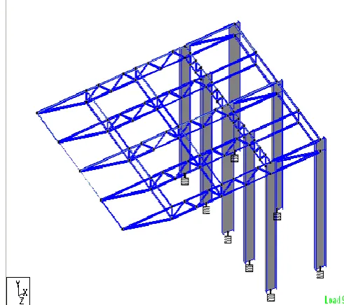
Figure 3. 3D (isometric) view of basic frame model of pipe (circular tube) section
VII.
ANALYSIS AND DESIGN:The cantilever frame has been idealized as space frame and for above loadings and self weight was calculated internally in the program, Analysis is carried out with the various load combinations.
LOAD COMB 9 1.0(DL+LL) LOAD COMB 10 0.75(DL+EQX) LOAD COMB 11 0.759DL+EQ-X) LOAD COMB 12 0.75(DL+EQZ) LOAD COMB 13 0.75(DL+EQ-Z)
LOAD COMB 14 0.75(DL+TEMPERATURE) LOAD COMB 15 0.75(DL+WL)
The design of cantilever space frame structure is for maximum moments and axial forces for each member based on IS 800 and all members are designed using pipe sections and with the help of steel take off total weight of the structure is known, thus by comparing with tube, angle &pipe sections. The pipe (circular tube) section is more economical than other two sections.
VIII.
RESULTS AND DISCUSSIONS:The out put obtained from the staad model to study different parameters such as Support Reactions ,Bending moments ,Axial forces, Moments and Stresses and steel take off for different sections are discussed with tables and graphs.
SUPPORT REACTIONS For (DL + LL) combinations
Only vertical reactions, Fy are considered
At each joint Pipe section forces are compared with Angle and Tube section. Hence bearing connections required are of less weight and off less strength which ultimately reduce the cost of the project.
FORCES AND MOMENTS
For different load combinations, Maximum and Minimum forces and moments for different sections are considered for analysis.
Maximum Fx is more for Angle and Tube sections when compared to Pipe section. This in turn reduces the length of the welding and cost of joints for pipe section.
STEEL TAKE OFF
Steel take off in pipe is less than 4 to 18% when compared to Tube and Angle sections; hence the cost of the project will get reduced.
Tables and Graphs:
REACTIONS FOR DIFFERENT SECTIONS TABLE-1
SUPPORT REACTIONS FOR 9 DL+LL
Node L/C TUBE ANG PIPE
51 9 DL+LL 2.451 2.625 1.726
52 9 DL+LL 3.321 3.466 3.246
53 9 DL+LL 2.21 2.454 1.737
149 9 DL+LL 10.821 10.15 9.447 150 9 DL+LL 20.344 18.852 17.403 151 9 DL+LL 10.815 9.443 8.776 174 9 DL+LL 1.019 1.502 0.828 175 9 DL+LL 1.022 1.484 0.827
Maximum Moments for Different Sections
TABLE-2
PIPE TUBE ANGULAR
Max Fx 78.062 78.387 89.403
Max Fy 5.133 5.992 10.267
Max Fz 1.618 0.381 7.167
Max Mx 1.772 1.155 2.515
Max My 12.766 15.364 25.874
Max Mz 104.256 106.844 109.321
IX.
CONCLUSIONS1. By comparing the output of Staadpro (a commercial software package) design results of different sections such as tube (square), pipe (circular tube), and angular sections it is concluded that, the steel take off for pipe (circular tube) section is 4% less than square tube section in weight & 18% less than angle section in weight when compared to other two sections. This gives a 10% saving in total weight of steel required for frame.
This increases number of rivets, length of welding and cost of joints.
3. Finally pipe (circular tube) section is more economical when compared to other two (angle, square tube) sections.
X.
REFERENCES[1]. N.subramanian, Principles of Space Structures-A comprehensive Review ,Southern Builder,vol v,no.14,march 1976,pp.9-15
[2]. Fan,F.;Shen,S.Z.;Parke.G.A.R .International Journal of space Structures Volume-19 Number 4,December 2004,pp.195-202(8)
[3]. Schimidit L.C.;Selby S:International Journal of SpaceStructures,volume-14,November 1, 1 January 199,pp.17-23(7)
[4]. Xudong,xu,ono,testuro;fulin,Guan:International Journal of SpaceStructures,volume-22,November 4,December 2007,pp 225-231(7)
[5]. Changuguo,wang;yunliang,li;Xingwen,Du;Xiaod
ong,: International Journal of
SpaceStructures,volume-22,November 4,December 2007,pp
[6]. Eberlin,h.,Latticed Space-Structures-A
Comprehensive
Review,Aceir-stahl-steel,vol40,no-2,feb 1975,pp.50-66.
[7]. Long span Roof Structures, Proceedings of the
Symposium held at
St.lous,oct.1981,proc.published by ASCE,368pp [8]. IS: 800-1984 code of practice for general
construction in steel (second revision).
[9]. IS:1161-1998 code of practice for steel tubes for structural purpose and steel design calculations and specifications.
[10]. IS 875(Part-1)-1987 code of practice for design loads (other than earthquake) for buildings and structures: part-1dead loads - unit weight of building materials and stored materials.
[11]. IS 875(Part-2)-1987 code of practice for design loads (other than earthquake) for buildings and