STRESS ANALYSIS OF COMPOSITE
PROPELLER BY USING FINITE
ELEMENT ANALYSIS
Dr.Y.SEETHARAMA RAO, Dept of Mechanical Engg, G.V.P College Of Engineering,
Visakhapatanam, PIN:530048 Andhrapradesh,
India
[email protected] Dr.K. MALLIKARJUNA RAO
Dept of Mechanical Engg, J.N.T.U College of Engineering,
Kakinada, PIN:533005 Andhrapradesh,
India
B.SRIDHAR REDDY Dept of Mechanical Engg, G.V.P College Of Engineering,
Visakhapatanam, Andhrapradesh,
India
Abstract:
Present work proposes a methodology to design a propeller with a metal and composite material to analyze its strength and deformation using Ansys software. In order to evaluate the effectiveness of composite over metals, stress analysis is performed on both composite and metal propeller using Ansys. Proposed methodology showed substantial improvements in metal propellers. The mean deflection, normal stress and shear stress were found for both metallic and composite propeller by using Ansys. From the results, stress analysis composite propeller is safe resonance phenomenon. In this work effort is made to reduce stress levels so that advantage of weight reduction along with stresses can be obtained. The comparison analysis of metallic and composite propeller was made for the maximum deformation and normal stresses.
Keywords: Composite Propeller, FEA, Stress Analysis
1. Introduction:
Ships use propeller as propulsion device for converting shaft power of the engine to thrust force for the ship to move it through water. Presently conventional marine propellers remain the standard propulsion mechanism for surface ships and under water vehicles. The propeller blade geometry and its design are complex involving many controlling parameters. The strength analysis of such complex 3D blades with conventional formula will give less accurate values. In such cases finite element method gives comparable results with experimental values.
studied the advantages of a composite propeller blde with fibre reinforced plastic over that of the propeller blade made from over materials. Gau FengLin [10] carried out a stress calculations for fibre reinforced composite thrust blade.
2. Analytical methods to find out stresses in a blade section:
The calculation of the stresses in a propeller is extremely complicated owing to a number of reasons: the loading fluctuates, its distribution over the propeller blade surface is difficult to calculate, and the geometry of the propeller is rather complex. It is therefore usual to use simplified methods to calculate the stresses in the propeller blades and to adopt a large factor of safety based on experience.
The simple method described here is based on the following principal assumptions:
i) The propeller blade is assumed to be a cantilever fixed to the boss at the root. The critical radius is just outside the root fillets.
ii) The propeller thrust and torque, which arise from the hydrodynamic pressure distribution over the propeller blade surface, are replaced by single forces each acting at a point on the propeller blade.
iii) The centrifugal force on the propeller blade is assumed to act through the centroid of the blade, and the moment of the centrifugal force on the critical section can be obtained by multiplying the centrifugal force by the distance of the centroid of the critical section from the line of action of the centrifugal force.
iv) The geometrical properties of the radial section (expanded) at the critical radius may be used instead of a plane section of the propeller blade at that radius, and the neutral axes may be taken parallel and perpendicular to the base line of the expended section.
Let the propeller have Z blades, and be turning at a revolution rate n when developing a thrust T with a torque Q. J.P.Ghose [11] suggested the following formulas.
Thrust force per blade,
T
Z
F
T
1
_______(1)Torque force per blade,
R
Q
Z
F
Q
1
_________(2)Centrifugal force,
.
r
2
n
2g
W
F
c
n
r
g
W
22
4
_(3)3. Finite element analysis of metallic and composite propeller:
In the present problem, element type solid 46 is used for composite propeller and solid 45 is used for Aluminum propeller.
3.1 Finite element modeling of the Propeller:
Fig:1 Final solid model of propeller
3.2 MESH GENARATION USING HYPERMESH
The solid model is imported to HYPERMESH 10.0 and hexahedral mesh is generated for the same. The meshed model is shown in figure 5.2. The meshing was done by splitting it into different areas and the 2D mapped mesh was done and then it was converted into 3D mesh using the tool linear solid. The number of elements created is 27,388 and number of nodes created is 52,412. Quality checks are verified for the meshed model. Jacobian, warpage and aspect ratio are within permissible limits. Now the pressures are applied on the propeller which is obtained in FLUENT 6.3. Then the meshed model is imported into the ANSYS.
Fig:2 Aluminium propeller meshed model
For meshing the composite propeller the solid model is imported in to hyper mesh and the elements are selected for various layup sequence as given by their thickness. Assure that proper connectivity exists between the layers. Now again the pressures are applied on the propeller which is obtained in FLUENT 6.3. Then the meshed model is imported into the ANSYS.
Fig:3 Composite propeller meshed model
3.3 EXPORTING MESH TO THE ANSYS11.0
First delete all the surfaces and 2d elements before exporting to the ANSYS so that only 3D elements are exported. Now select the user profile in the preferences then go to utility menu and mention the ET type as solid45 if it is aluminium or solid 46 for composite material, specify material properties and real constants if necessary. Then go to 3D option and mention the ET type and element types. Update all the components in the component option and at last renumber all the components. Now go to export option to export the FE model to the ANSYS.
3.4 Material properties of propeller:
Aluminum properties
Young’s modulus E= 70000 MPa Poisson’s ratio NUXY=0.34 Mass density =2700 kg/m3
Damping co-efficient =0.03
Material properties for composite Propeller used for present work
Mat no 1: S2Glass fabric/Epoxy
Ex =22.925Gpa
Ey =22.925Gpa
Ez =12.4Gpa NUXY =0.12
NUYZ =0.2
NUZX =0.2
Gxy =4.7Gpa
Gyz=Gzx =4.2Gpa ρ =1.8gm/cc
Mat no 2: Carbon UD/Epoxy
Ex =120Gpa
Ey =10Gpa
Ez =10Gpa
NUXY =0.16
NUYZ =0.2
NUZX =0.16
Gxy =5.2Gpa
Gyz =3.8Gpa
Gzx =6Gpa
ρ =1.6gm/cc
3.5 BOUNDARY CONDITIONS AND LOADS
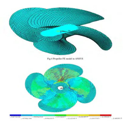
Fig:4 Propeller FE model in ANSYS
Fig:5Propeller FE model in ANSYS Pressures
4. RESULTS AND DISCUSSIONS:
Propeller made of Aluminum and another one made of composite material is chosen for FE analysis. In present the results of stress analysis are presented in the form of figures and graphs by selecting the effective software like ANSYS.
STRESS ANALYSIS OF ALUMINIUM PROPELLER
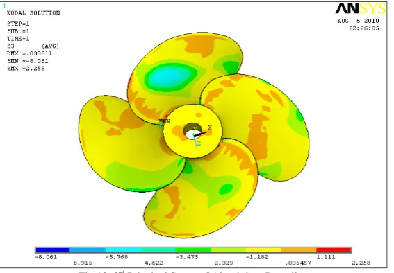
The deformation of aluminium propeller is shown in figure 6 and the maximum deflection was found as 0.038611mm. The stresses and displacements in x, y and z directions are shown in table 1.
Table :1 Static analysis results of Aluminium Propeller
Aluminium Propeller Results
Deflection 0.038611mm
Max. Normal stress 9.011 N/mm2
First principal stress 12.405N/mm2
Second principal stress 4.849N/mm2
Third principal stress 2.258N/mm2
Table :2 Maximum stress at the root section
FROM ANSYS FROM BURILL METHOD
Fig:6 Deformation of Aluminium Propeller
Fig:7 Stress of Aluminium Propeller in X-direction
Fig:9 Stress of Aluminium Propeller in Z-direction
Fig:10 1st Principal Stress of Aluminium Propeller
Fig:12 3rd Principal Stress of Aluminium Propeller.
STRESS ANALYSIS OF COMPOSITE PROPELLER
Stress analysis of composite propeller is carried out so as to check the bonding strength between various layers of composite propeller and Inter-laminar shear stresses are calculated.
Maximum deflection for composite propeller with 40 layers was found to be 0.27504 mm as shown in figure 13. The maximum normal stress was found to be 7.995 N/mm2 in x-direction as shown in figure 14. Table 3 shows induced deformations and stresses in composite propeller.
The deflection for composite propeller was found to be around 0.27504mm mm for all layers which is more than that of Aluminum propeller i.e. 0.038611mm.Interlaminar shear stresses were calculated for composite propeller for 40 layers and the maximum inter-laminar shear stress is found on the layer 40.
Table :3 Stress analysis results of composite propeller
Composite Propeller Results
Max deflection 0.27504mm
Max. normal stress 7.992/mm2
Maximum Inter-laminar shear stress 1.353N/mm2
Fig14: Stress of composite propeller in X-direction
Fig15: Stress of composite propeller in Y-direction
Fig16: Stress of composite propeller in Z-direction
CONCLUSIONS
The following conclusions are drawn from the present work
1. The stresses of composite propeller obtained in static analysis are within the allowable stress limit.
2.The maximum deflection for the aluminium propeller is 0.038611mm and the maximum deflection for the composite propeller is 0.275 mm.
3. The maximum normal stress for the aluminium propeller is 9.011 N/mm2 and the maximum normal stress for the composite propeller is 7.99N/mm2 , from analytical method 8.9 MPa.
[9] W.J.Colclough and J.G.Russel. “The Development of a Composite Propeller Blade with a CFRP Spar” Aeronautical Journal, Jan 1972, pp53-57.
[10] Gau-Feng Lin “Three Dimensional Stress Analysis of a Fiber Reinforced Composite Thruster Blade”, the society of naval architects and marine engineers ,1991.