Vector Modulator for Phase Shifting in
Passive Beamforming Wireless Systems
P.Sampath1, K.Gunavathi2
1Lecturer, 2Professor,
ECE Department, PSG College of Technology, Coimbatore, India. Abstract
This paper proposes vector modulator for changing the phase of a signal in passive beamforming system. Vector modulator is used to perform a phase shift function with added benefit of amplitude control. It is used to improve the directivity of RF waves in Wireless systems. Vector modulator is implemented for a center frequency of 902.5 MHz. The simulation is performed for individual blocks of the vector modulator and for vector modulator with JFET and MOSFET as controlling device in the variable attenuator of the vector modulator.
Keywords
Vector modulator, Hybrid Coupler, Wlkinson Splitter and Variable attenuator I. INTRODUCTION:
A narrow band phased array system designated to yield single antenna beam can be obtained with phase shifters or vector modulators. Vector modulator provides a compact, low power, and moderate lossy way to modulate a signal. Vector modulator (VM) allows the reduction of the side lobe level, while being able to accurately point the antenna beam in any direction. Phase shifts ranging between 0o to 360o can be obtained in increments that depend on the phase tracking accuracy. In the adaptive beamforming system, the pointing of the beam in the azimuthal direction is accomplished by Vector Modulator [1]. The requirements for vector modulators are Phase/Amplitude accuracy over the system bandwidth and the range of phase shifts, Minimum amplitude variations between the phase states and minimal insertion loss and low power consumption. Among the above requirements minimum insertion loss is of paramount importance because it affects the system noise figure.
VM converts a signal to a desired vector location by control signal and being an analog circuit, offers unlimited resolution capability. Any sinusoidal signal can be expressed as a vector having the properties of both amplitude and phase with respect to a reference signal. If a signal is represented as a vector in a polar coordinate system with coordinates of amplitude and phase, it can also be defined in a rectangular coordinate system as In-phase (I) and Quadrature (Q) components of the output signal. The output is analyzed at receiver end for wireless systems operating at 902.5 MHz center frequency.
II. PROPOSED VECTOR MODULATOR:
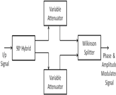
The general block diagram of a vector modulator is shown in Figure 1.
The basic modules in the VM are hybrid coupler, Wilkinson splitter/combiner and variable attenuator [2], [3]. The Wilkinson splitter is used as power combiner. The operation of VM is the input signal is divided into two equal signals 90° apart, i.e., I & Q signals. This allows the magnitude of each signal to be re-located along its vector axis. The two signals are then combined. Sum of the vectors produces the resultant output signal. I & Q control of vector modulators allows the reduction of the side lobe level and accurately point the antenna beam in any direction. The signal is split into two signals that are 90 degrees apart using hybrid coupler. I and Q components of the signal are then passed through independent variable attenuators, which can also provide 180 degree phase shift. Then the two signals are recombined using a Wilkinson Combiner. As a result when the input signal is given at a particular phase, by varying the control voltage of the variable attenuator within the range we obtain the required phase shift at the center frequency. The signal can be steered in the desired direction which improves the directivity of RF waves in wireless systems.
III. HYBRID COUPLER:
Hybrid couplers are the special case of a four-port directional coupler that is designed for a 3-dB (equal) power split [4]. Hybrids couplers are of two types, 90 degree or quadrature hybrids and 180 degree hybrids. In this proposed VM circuit 90 degree hybrid couplers are considered. The basic configuration of a 90 degree hybrid coupler has two cross-over transmission lines over a length of quarter wavelength, corresponding with the center frequency of operation.
When power is introduced at the input port, half the power (3dB) flows to the port 2 and the other half is coupled to the port 3. Reflections from mismatches sent back to the output ports will flow directly to the port 4 or get cancelled at the input. This makes hybrids more suitable to split high power signals in applications where unwanted reflections could easily damage the driver device. 3dB, 90° hybrids are also known as quadrature hybrids because a signal applied to any input, will result in two equal amplitude signals that are 90° out of phase. The relationship at the output remains the same as these devices are electrically and mechanically symmetrical. This configuration ensures a high degree of isolation between the two output ports and the two input ports. The scattering matrix for a matched, lossless, reciprocal 4-port device is given as
0
0
0
0
[ ]
0
0
0
0
j
j
S
j
j
(1)and for hybrid coupler since
1 2
, the scattering matrix of quadrature hybrid coupler is
0 1 0
1 0 0
1 [ ]
0 0 1
2
0 1 0
j j S j j (2)
Hybrid coupler is designed for the desired center frequency using the following equations for transmitter and receiver by assuming R=50 ohm, Z=50 ohm (characteristic impedance)
1
1
C
Z
(3)
(
1)
R
L
C Z
(4)
0 2 1
1
C
C
L
(5) and ω=2πf, where f is the centre frequency.
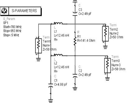
S-parameter simulation is performed for the Hybrid couplers to find the return loss, isolation and whether the input signal is split at the -3dB point. The schematic of the Hybrid coupler operating at 902.5MHz is shown in Figure 4 and the S-parameter results are shown in Figure 5.
Figure 4 Hybrid coupler operating at 902.5MHz
b) S41
c) S31 and S21
d) Phase plot of hybrid coupler
Figure 5 S-parameter results of Hybrid coupler at 902.5 MHz
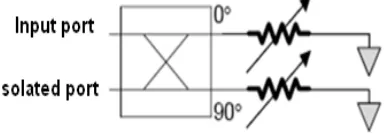
designing or using variable RF attenuators, it is necessary to ensure that the RF attenuator retains constant impedance over its operating range to ensure the correct operation of the interfacing circuitry. Variable attenuator has been implemented for controlling the amplitude of the signal using a control voltage. A hybrid coupler is placed along with the variable attenuator to bring about necessary phase change. The arrangement of variable attenuator is shown in Figure 6.
Figure 6 Variable Attenuator with hybrid coupler
The circuit schematic and the simulation results of the variable attenuator are given in Figure 7 and Figure 8 respectively.
Figure 7 Schematic of Variable Attenuator
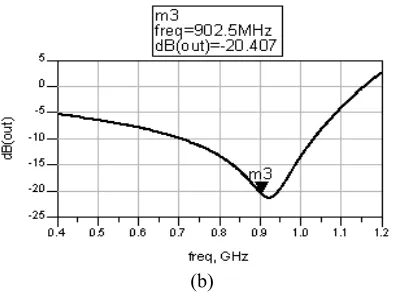
(b)
Figure 8 Simulation Results of Variable Attenuator
The variable attenuator simulated for 902.5MHz provides an attenuation of around 20.407dB at the designed frequency.
V. WILKINSON POWER COMBINER:
The Wilkinson power splitter splits an input signal into two equal phase output signals, or combines two equal-phase signals into one in the opposite direction [4]. Quarter-wave transformers were used to match the split ports to the common port. Because a lossless reciprocal three-port network cannot have all ports simultaneously matched, one resistor is added in between. The resistor does a lot more than allow all three ports to be matched; it fully isolates port 2 from port 3 at the center frequency. The resistor adds no resistive loss to the power split, so an ideal Wilkinson splitter is 100% efficient. Wilkinson splitter/combiner in its simplest form is an equal-amplitude, two-way splitter/combiner as a three-port circuit is shown in Figure 9. The arms are quarter-wave transformers of impedance 1.414xZ0.
Figure 9 Ideal two port Wilkinson power Combiner
For designing the Wilkinson splitter/combiner characteristic impedance is considered to be Z0=50 Ohms and Z = Z0.√2=70.7 Ohms
Cp = 1/(ω.Z) (6)
Ls = Z/ω (7)
and ω =2πf, where f is the center frequency.
Figure 10 Circuit Schematic of Wilkinson Combiner at 902.5MHz
(a) Magnitude of S21
(c) Magnitude of S11
(d) Phase of S21
(e) Phase of S31
Figure 11 S-parameters of Wilkinson splitter/Combiner
Table 1 S-parameters for the Wilkinson combiner
Center freque
ncy
Magnitude in
dB Phase in degrees S21 S31 S11 S21 S31 902.5
and S31 shows that the signals are in phase. This circuit effectively combines the signals input at port 2 and port 3 into a single signal with minimum loss.
VI. VECTOR MODULATOR:
Vector modulators are implemented by using either JFET or MOSFET as a voltage control device in the variable attenuator of the vector modulator. The circuit of vector modulator with JFET is shown in Figure 12.
Figure 12 Vector modulator with JFET
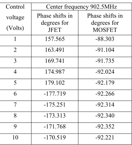
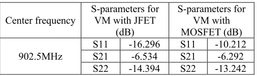
The Vector modulator with MOSFET is obtained by replacing JFETs with MOSFETs. The simulation results of the vector modulator for various control voltages at different frequencies with JFET and MOSFET are given in Table 2 and the various S-parameters like insertion loss (S21), input return loss (S11) and output return loss (S22) for the variable attenuators are given in Table 3.
Table 2 Simulation results of Vector modulator
Control voltage (Volts)
Center frequency 902.5MHz Phase shifts in
degrees for JFET
Phase shifts in degrees for
MOSFET
Table 3 S-parameters of vector modulator
Center frequency S-parameters for VM with JFET (dB)
S-parameters for VM with MOSFET (dB) 902.5MHz
S11 -16.296 S11 -10.212 S21 -6.534 S21 -6.292 S22 -14.394 S22 -13.242
The S-parameters of the vector modulator show that the input return loss and output return loss are low and the insertion loss is also very low.
VII. CONCLUSION:
The implementation of vector modulators with Hybrid coupler, variable attenuator and Wilkinson splitter elements has been presented. The simulation results show that the vector modulators can work for different control voltages from 1V to 10 V. The hybrid coupler implemented splits the input signal into in-phase and Quadrature components with equal power. The Wilkinson combiner used to combine the in-phase and Quadrature signals from the variable attenuators combines the signals with minimal loss. The variable attenuators control the amplitude of the in-phase and Quadrature signals and provides necessary phase shift when connected with Wilkinson combiner and hybrid coupler. The vector modulators with JFET as control element in variable attenuator give large phase shifts can be used in beamforming systems where the beam has to be steered with large phase shifts. The vector modulators with MOSFET as control element gives small phase shifts of the input signal and can be used in beamforming systems where the signal is to be steered slowly.
VI. REFERENCES
[1] Fakoukakis. F. E, Diamantis. S. G, Orfanides. A. P and Kyriacou. G. A, “Development of an Adaptive and a Switched Beam Smart Antenna System for Wireless Communications”, Progress In Electromagnetics Research Symposium, August 2005.
[2] Egan, Jonathan “A 2.4 GHz Vector Modulator MMIC Design EE787”, Microwave Journal, 2006. [3] Penn John E, “A Balanced Vector Modulator MMIC”, Microwave Journal, June 2005.
[4] David M.Pozar, “Microwave Engineering” 3rd Edition, John Wiley and Sons, 2007 Reprint, Sanat Printers, Haryana, India.
[5] Jonathan Egan, “Vector Modulator –Final Report”, MMIC Design Contest, 2006.
AUTHOR’S BIOGRAPHY
1P.Sampath, Lecturer, in the Department of Electronics and Communication Engineering, PSG College of Technology,Coimbatore. He has
Published 5 research papers in International and National Journals. E-mail: [email protected]
2Dr.K.Gunavathi, Professor, in the Department of Electronics and Communication Engineering, PSG College of Technology, Coimbatore. She
has published more than 70 papers in International and National Journals.