NETWORK NODE DETECTION SYSTEM
USING BORDER PATROL
Kavya Aennem
1, Sai Charan Dhatrika
2, Deepika Puvvula
31
B.Tech Scholar,
2Assistant Professor CSE Dept., Bharat Institute of Engineering & Technology,
Ibrahimpatnam,,R.R Dist. 501510, Telangana State. (India)
3
Assistant Professor, CSE Dept., ANITS Engineering College, Visakhapatnam- 531162. A.P, (India)
ABSTRACT
The system aims at an efficient way of retrieving all the information of the current node. It gives information of
our system like host name, ip address, what type of OS is installed. And also it illustrates availability of RAM
memory in our system. So the user can know that information and he can make use of that system as per his
requirement. And also it can control the blockage occurred between two hosts. However there are host-to-host
blockage control algorithms which are inadequate in avoiding the blockage breakdown and unfair bandwidth
allocations that are irresponsive to network blockages. To avoid these problems, we propose blockage
avoidance mechanism called Network Node Detection System which uses the Border Patrolling Technique. It
works depending on exchange of feedback passed between the edge routers arranged at the borders of networks
in order to restrict and control the irresponsive packet flows before they enter in to the network. It simulates
that this mechanism effectively eliminates blockage breakdown and achieves approximate min-max fair
bandwidth allocations between competing nodes.
Keywords:
Blockage Breakdown, Blockage Control, Border Control, Core-Stateless Mechanism,
Egress, Host-To-Host Argument, Ingress.
I. INTRODUCTION
Giving information to the user about the system on which he is working and make report for easy use of users.
So that he can make use of resources available to him very efficiently.
Actually the retrieval of system’s information for the user’s benefit is proposed by the Defense Research
Development Laboratory and we have enhanced it to Network Node Detection System with Border Patrol by
embedding the Border Patrol to the network and provide security to avoid blockage.
And the scalability is a host-to-host argument; it is maintained by pushing the complexity to the network edges.
We have a best example of internet philosophy: the TCP blockage control is achieved by implementing some
algorithms at the destination host, but as TCP blockage control illustrates some of the host-to-host argument’s
shortcomings the current Internet suffers from two strategies:
1.1
Blockage Break-Down
This blockage breakdown occurs from undelivered packets when bandwidth is continually consumed by
retransmission of packets leads to the poor calculation time of retransmission timers by TCP [2] [3] sources,
which causes blockage breakdown. Recently this problem becoming more common. Network applications are
using transport protocols, such as UDP, which are unaware to blockage, so it makes no attempt to reduce the
packet transmission rates when packets are discarded by the networks as it is not accurate in packet
transmission [4]. Some applications increase their transmission rates during blockage periods, so that they
will be less sensitive to packet losses [5]. Unfortunately, the Internet currently has no effective way to
regulate such applications.
1.2
Unjustified Bandwidth Allocation
Unjustified bandwidth allocation occurs for so many reasons, one of them is the presence of application which
do not adapt to blockage.
To point-out these strategies, we introduce and investigate a new Internet traffic control protocol called as
Network Border Patrol.
The basic principle of this NBP is to examine the rate of packets that are entering in to and leaving from the
network at the borders of the network. If the flow of packets entering the network is more than they are leaving
form the network, then the flow of packets is buffered or discarded. It means that, the network is receiving more
packets than what it can handle. To prevent this scenario, NBP performs “patrolling” at the network borders and
ensures that the packets do not flow in to the network with higher rate than they are able to leave it. This
patrolling prevents blockage breakdown from undelivered packets, because these irresponsive packets never
enter the network in the first place.
This NBP can also provide approximately max-min fair bandwidth allocations to complete the packet flow
by using some mechanisms. Weighted Fair Queuing is an example of one such mechanism. WFQ shows
significant complexity on routers by requiring them to maintain per-flow state and per-flow scheduling of
packets.
Here, we introduce an enhanced core-stateless fair queuing mechanism, in order to achieve some of WFQ’s
advantages without all of its complexity.
II. METHODOLOGY
Border patrol is a network layer blockage avoidance protocol that is aligned with an approach called core
stateless approach. This approach allows routers on the borders (or edges) of a network to perform flow
classification and maintain per-flow state on the borders (or edges) of a network but does not allow routers
core of the network to do the same. In this approach we have two edge routers at the borders of the
networks other than the core routers. Depending on flow of packets an edge router may be viewed as an
ingress router or an egress router. Note that, ifthe flow of packets passing through multiple networks then
that flow may pass through more than one ingress or more than one egress routers.
2.1Ingress Router
An edge router working on the flow of packets that are passing in to the edge routers network is called as
“Ingress router”.
ingress router. Also it sends a feedback to the egress router and receives feedback from the egress router.
2.2 Egress Router
“Egress router” is an edge router operating on a flow of packets passing out of a network.
It monitors the per-flow rate of packets, which are leaving out of network. And gives a feedback to the ingress
router about per-flow rate of packets it is monitored. The ingress router controls the packets flow by
considering egress router’s feedback.
The Border patrol works with the combination of ingress router and egress router.
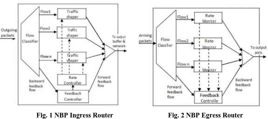
Fig. 1 NBP Ingress Router Fig. 2 NBP Egress Router
Actually
here, both ingress router and egress router work together by sending feedbacks to each other to avoid the blockage breakdown. As an ultimate result, congestion free data will be transmitted and also fair bandwidthis allocated between the networks.
Rate monitoring allows an egress router to determine how rapidly each flow’s packets are leaving the network,
whereas rate control allows an ingress router to police the rate at which each flow’s packets enter the network.
These two routers exchange the feedback packets with each other. An ingress router sends forward feedback
packets to an egress router to inform about the rate of flows that are being controlled, and an egress router sends
backward feedback packets to an ingress routers to inform about rate of packets that are leaving the network
(the packets are leaving the network with same flow’s rates at what rate each flow’s packets are entering the
network).
III. ARCHITECTURE ILLUSTRATION
Here the NBP describes three important aspects:
3.1 Architecture
3.2 Feedback control algorithm
3.3 Rate control algorithm
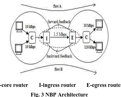
C-core router I-ingress router
E-egress router
Fig. 3 NBP Architecture
Here, we are modifying only the edge routers of the network to avoid the blockage breakdown problem. To do
so, the ingress router’s output ports and egress routers input ports must be modified especially to exchange
and handle feedbacks. The flow of data packets are classified sent by ingress routers arrive at the input port of
the egress router. In the case of IPv6, this process is done by examining the packet header of flow label,
whereas in the case of IPv4, it is done by examining the packet’s source and destination addresses and port numbers.
Fig. 1 illustrates the architecture of ingress router. The output ports of ingress routers contains a flow
classifier, per-flow traffic shaper(like leaky buckets), a feedback controller and a rate controller.
The flow classifiers classify the packets in to flow.
The traffic shapers limit the rate of packets from individual flows that enter the network.
The feedback controller receives the backward feedback packets, that are sent by the egress routers and
passes their contents to the rate controller. It also generates forward feedback packets, which accordingly
transmitted to the networks egress routers.
The rate controller adjusts traffic shaper parameters according to some rate control algorithms like TCP.
Fig. 2 illustrates about the Egress router. At the input ports of egress router bit rate of each flow is monitored
using a rate estimation algorithm such as Time Sliding Window (TSW). These rates are collected by a
feedback controller to send them as backward feedback packets to an ingress router whenever a forward
feed-back packets arrives from that ingress router.
3.2 Feedback Control Algorithm
The feedback control algorithm find outs when the feedback packets are exchanged and how they are
exchanged between edge routers. The feedback packets are taken in the form of ICMP packets especially for
three reasons.
i. These packets allow egress routers to findout which ingress routers are controlling the packets that are
monitored by the egress routers.
ii. They allow egress router to communicate with egress routers.
iii. They allow ingress routers to detect blockage situation in an early stage of existence in a network, by
The forward feedback packet contains time stamp and a list of flow specifications for flows originating at the
ingress router. Time stamp is used to calculate the round trip time between two edge routers, and the list of flow
specifications are values indicates the active flows identities to an egress router originating at the ingress router.
When a forward packet is received by the egress router it generates a backward feedback to the ingress router
that contains forward feedback packets actual time stamp, a router’s hop count and a list of observed bit rates
called egress rates. The router hop count is used by the ingress router’s rate control algorithm, to indicate how
many routers are present in the path.
When the backward feedback packet arrives at the ingress router, its contents are passed to the ingress router’s rate controller, which uses them to adjust the parameters of each flow’s traffic shaper.
Psudo code for ingress router rate control algorithm is:
On arrival of Bward Fback packet B from egress router E
currentRTT = currentTime - B.timestamp;
if (currentRTT < E.baseRTT)
E.baseRTT = currentRTT;
deltaRTT = currentRTT - E.baseRTT;
RTTsElapsed = (currentTime - E.lastFbackTime) / currentRTT;
E.lastFbackTime = currentTime;
for each flow F listed in B
rateQuantum = min (MSS / currentRTT, F.ERate / QF);
if (F.phase == SLOW_START)
if (deltaRTT *F.InRate < MSS .hopcount)
F.InRate = F.InRate * 2 ^ RTTsElapsed;
else
F.phase = CONGESTION_AVOIDANCE;
if (f.phase == CONGESTION_AVOIDANCE)
if (deltaRTT *F.InRate < MSS .hopcount)
F.InRate = F.InRate rateQuantum *RTTsElapsed;
else
F.InRate = F.ERate - rateQuantum;
3.3 Rate Control Algorithm
The rate control algorithm regulates each flow’s rate that enters the network. In this algorithm, there are two
phases. They are slow start or blockage avoidance. The flow can be in any one of those two phases that are
similar to the TCP blockage control. New packets of network enter in to the slow start and proceed to the
blockage avoidance phase only when the flow has experienced blockage.
Algorithm
Calculate the currentRTT(round trip time) between edge routers and update the baseRTT if necessary.
The baseRTT reflects the best observed RTT between the two edge routers.
Then deltaRTT = currentRTT – E.baseRTT;did, and this can only be due to the buffering of packets within the network.
if( F.InRate * deltaRTT> .hopcount
if(deltaRTT>(In.hop – E.hop) * largPacket; then the flow congestion has occurred.IV. ADDING FAIRNESS TO NNDSBP
Although this paper prevents blockage breakdown, it does not guarantee that all flows are allocated a fair
bandwidth when they compete for bottle neck. We consider the interoperation and different fair queuing
mechanisms.
This fair bandwidth allocation can be achieved by implementing per-flow packet scheduling mechanisms like
Fair Queuing (FQ) [7], [8]. FQ attempts to estimate the behavior of a fluid flow system; in this process each
packet stream is treated as a fluid flow entering in to a pipe, and all flows receives an equal proportion of pipe’s
capacity. As queuing is very effective, it allocates a fair bandwidth to packet flows which are competing for a
single link. In order to provide this facility, FQ requires each link to maintain queues and state for each flow.
This complexity overflow obstructs the scalability of FQ, thousands of networks are active at any time for a
wide area making it unfuctional. Picking out the scalability complexities of FQ, several researches have
proposed more scalable core-stateless approximations, like Core-stateless FQ [9], Rainbow FQ [10] and
CHOke. The general idea behind these mechanisms is that edge routers label packets entering the network with
the state of their associated flows, and core routers use the state recorded in the packets to decide whether to
drop them or when to schedule them for transmission. This makes the core-stateless mechanisms more scalable
than the FQ, because they limit per-flow operations and state maintenance to the routers on the network edges.
Although these core-stateless fair queuing mechanisms work well with most blockage control algorithms that
rely on packet losses to indicate congestion, they do not work as well with blockage breakdown algorithms that
prevent blockage before packet loss occurs.
V. SIMULATION
We have 3 simulations here,
5.1 Preventing Blockage Breakdown
5.2 Achieving Fair Bandwidth Allocation
5.3 Scalability
5.1
Preventing Blockage Breakdown
Let us consider an application generates a TCP flow which always has data to send, and the other is an
unresponsive constant bit rate UDP flow. Both compete for access to a shared 1.5 Mbps bottleneck link (I- E),
and only the UDP flow traverses a second bottleneck link (C2-E), which has a limited capacity of 128 kbps. Fig.
3 shows the throughput achieved by the two flows as the UDP source’s transmission rate is increased from 32
kbps to 2 Mbps. The combined throughput delivered by the
network (i.e., the sum of both flow
throughputs).
The one of its four scenarios is, the benchmark case used for comparison: NBP is not used between edge routers,
transmission rate increased the network experienced with severe blockage breakdown, because the UDP flow
fails to respond adaptively to the discarding of its packets on the second bottleneck link. The
TCP flow’s throughput drops nearly to zero when the UDP load increases to 1.5 Mbps.
5.2 Achieving Fair Bandwidth Allocation
This paper not only target on blockage breakdown, but also on fairness allocation. Fairness experiment, we
consider the scenario depicted in Fig. 3 but replace the second bottleneck link (C2-E) with a higher capacity 10
Mbps link. The TCP flow is generated by an application which always has TCP flow which always has data to
send, and the other is an unresponsive constant bit rate UDP flow. Both compete for access to a shared 1.5 Mbps
bottleneck link C1 and only the UDP flow traverses a second bottleneck link (C2-E), which has a limited
capacity of 128 kbps.
Since there is only one 1.5 Mbps bottleneck link (I - E) in this scenario, the max-min fair allocation of
bandwidth between the flows is 750 kbps (if the UDP source exceeds a transmission rate of 750 kbps). However
fairness is clearly not achieved when only FIFO scheduling is used in routers when unresponsive UDP traffic
load increases, the TCP flow experiences congestion and reduces its transmission rate, thereby granting an
unfairly large amount of bandwidth to the unresponsive UDP flow. So the ECSFQ is introduced for throughput
of each flow as
the ECSFQ is able to achieve approximate fair bandwidth allocations.
5.3 Scalability
It is an important measurement for any traffic control mechanism. As we saw in the previous section, our paper
is a core-stateless traffic control mechanism that effectively prevents blockage breakdown and provides
approximate max-min fairness. Its scalability is highly dependent up on per-flow management that edge routers
performed. In large network, the overheads of maintaining per-flow state, communicating per-flow feedback,
and per-flow rate control and rate monitoring may become expensive. The number of edge routers, the number
of flows, and the load of the traffic are the determinant factors in NBP’s scalability. The amount of feedback
packets of ingress router depends on the number of egress routers it communicates with and the load of the
traffic. The length of the feedback packets as well as the processing and the amount of state borders routers need
to maintain is mainly determined by the number of flows.
VI. RESULTS
The Snapshot(a) is the source window that appears when we run our application on the computer. It is showing
the information retrieved from the host. And also it is facilitating us to send the data to an intended destination
by giving destination address and the data that we want to send. We have to text fields to give the destination
Snap-Shot(a): Source Window
The Snapshot(b) is an ingress router that controls the blockage that may occur while sending data and also
provides max-min fair bandwidth allocation. It starts sending packets only after receiving some packets while
sending large data by controlling their flows. And it informs to the user, that the number of packets received by
the destination for user conformation. There by it is providing security for the data packets.
Snap-Shot(b): Ingress Router
The Snapshot(c) is an Egress router which is monitoring the rate of flow’s packets and sending backward
feedback to the ingress router. And it displays the data it received at the destination when we click on “view
details” button.
VII. CONCLUSION
We have retrieved host properties and configuration to make the information available to the user. Thereby
assist the user all the information about the system. And we have embedded the border patrol mechanism for the
internet to avoid the blockage that may occurs while passing the packets between two networks and enhanced
core-stateless fair queuing mechanism. So this project is able to make the systems information available to the
user, it prevents the blockage breakdown from undelivered packets and also achieves a fair bandwidth
allocation. It does this by ensuring that, each flow of packets does not enter the network faster than they are able
to leave it. It requires no modifications to the core routers, merely this mechanism was achieved by two
additional routers at the borders of the networks namely ingress router and egress router. The Ingress router is
implemented using two algorithms called leaky bucket algorithm and rate control algorithm. And Egress router
uses Time Slide Window (TSM) algorithm which allow the egress router to determine how rapidly each flow’s
packets are leaving the network.
The ultimate result shows that our paper successfully provides host information, prevents blockage breakdown
and achieving max-min fairness in band width allocation.
REFERENCES
[1] S. Floyd and K. Fall, “Promoting the Use of End-to-End Congestion Control in the Internet,” IEEE/ACM
Transactions on Networking, August 1999, To appear.
[2] J. Nagle, “Congestion control in IP/TCP internetworks,” Request for Comments 896, Internet Engineering
Task Force, Jan. 1984.
[3] Van Jacobson, “Congestion avoidance and control,” ACM Computer Communications Review, vol. 18,
no. 4, pp. 314– 329, Aug. 1988, Proceedings of the Sigcomm ’88 Symposium in Stanford, CA,
August, 1988.
[4] “Real Broadcast Network White Paper,” White paper, RealNetworks Inc., January 1999,
http://www.real.com/solutions/rbn/whitepaper.html.
[5] “RealVideo Technical White Paper,” White paper, RealNetworks Inc., January 1999,
http://www.real.com/devzone/library/whitepapers/overview.ht ml.
[6] J. Padhye, V. Firoiu, D. Towsley, and J. Kurose, “Modeling TCP Throughput: A Simple Model and its
Empirical Validation,” in Proc. of ACM SIGCOMM, September 1998, pp. 303–314.
[7] A. Demers, S. Keshav, and S. Shenker, “Analysis and Simulation of a Fair Queueing Algorithm,” in Proc.
of ACM SIGCOMM, September 1989, pp. 1–12.
[8] A. Parekh and R. Gallager, “A Generalized Processor Sharing Approach to Flow Control – the Single Node Case,” IEEE/ACM Transactions on Networking, vol. 1, no. 3, pp. 344–357, June 1993.
[9] I. Stoica, S. Shenker, and H. Zhang, “Core-Stateless Fair Queueing: Achieving Approximately Fair
Bandwidth Allocations in High Speed Networks,” in Proc. of ACM SIGCOMM, September 1998, pp.
118–130. 28.