Published online February14, 2015 (http://www.sciencepublishinggroup.com/j/ajee) doi: 10.11648/j.ajee.s.2015030401.12
ISSN: 2329-1648 (Print); ISSN: 2329-163X (Online)
Prediction of Smoke Propagation in a Big Multi-Story
Building Using Fire Dynamics Simulator (
FDS
)
Ahmed Farouk Abdel Gawad, Hamza Ahmed Ghulman
Mechanical Engineering Department, College of Engineering and Islamic Architecture, Umm Al-Qura Univ., Makkah, Saudi Arabia
Email address:
[email protected] (A. F. AbdelGawad)
To cite this article:
Ahmed Farouk Abdel Gawad, Hamza Ahmed Ghulman. Prediction of Smoke Propagation in a Big Multi-Story Building Using Fire Dynamics Simulator (FDS). American Journal of Energy Engineering. Special Issue: Fire, Energy and Thermal Real-life Challenges. Vol. 3, No. 4-1, 2015, pp. 23-41. doi: 10.11648/j.ajee.s.2015030401.12
Abstract:
In the present work, the computational fluid dynamics (CFD) technique was used to predict the fire dynamics in a big three-story building. Important aspects of fire dynamics were investigated such as smoke propagation and temperature distribution. The study aims to decrease the fire hazards by computationally predicting the expected smoke movement in real-life conditions. Consequently, early evacuation plans can be established to save human lives by proper estimation of the smoke direction and density. Also, temperature rise has a potential effect on the safety of both humans and structures. Different factors were considered such as fire location, doors, and emergency openings. Important findings and notable conclusions are recorded.Keywords:
Fire Dynamics, Smoke Propagation, Computational Method, Unsteady Solution1. Introduction
1.1. Importance
Due to the development of modern life, people may gather at the same time and place with intensive density. This situation may initiate series fires that lead to massive losses in human lives. Commonly, most of the deaths in fires are not due to direct fire, but because of suffocation with smoke, fumes and toxic gases. Usually, the lack of experience and awareness of individuals results in the increased risk and mortality rates.
Computational prediction of the most probable direction of smoke propagation assists to save human lives. Moreover, smoke-control schemes and evacuation plans can be established as part of the fire-safety strategy.
Examples of buildings where smoke prediction and control play a remarkable role include: holy and worship places, university campuses, shopping centers, big hotels, atrium buildings, large warehouse and industrial buildings, underground structures (car parks and tunnels), etc.
Usually, prediction and control of smoke flow within a building may cover one or more of the following objectives: (i) Assisting fire fighting, (ii) Guarantee safe flees for the occupants of the building, (iii) Protecting property.
1.2. Previous Investigations
The problem of fire dynamics simulation was investigated by many researchers. Men et al. [1] used large eddy simulations for studying fire-driven flows. Kashef et al. [2] carried out computational simulations of in-situ fire tests in road tunnels. Xin et al. [3] investigated computationally the turbulent buoyant flame using a mixture-fraction-based combustion model. Jahn et al. [4] concerned the effect of model parameters on the simulation of fire dynamics. Huo et al. [5] considered the locations of diffusers on air flow field in an office. Razdolsky [6] investigated mathematically the modeling of fire dynamics. Cheng and Hadjisophocleous [7] considered the dynamic modeling of fire spread in buildings. Ling and Kan [8] carried out numerical simulations on fire and analysis of the spread characteristics of smoke in a supermarket. Yang et al. [9] investigated both experimentally and numerically a storehouse fire accident. Zhang and Li [10] studied the thermal actions in localized fires in large enclosures. Sun et al. [11] investigated the progressive collapse analysis of steel structures under fire conditions. Wu and Chen [12] considered 3D spatial information for fire-fighting search and rescue route analysis within buildings. Agarwal and Varma [13] studied the fire-induced progressive collapse of steel building structures.
assess effectiveness of air sampling-type detector for the protection of large open spaces. Webb [15] used FDS
modeling for hot smoke testing in cinema and airport concourses. Smardz [16] validated FDS for forced and natural convection flows. Sun et al. [17] evaluated the fire-plume properties with FDS and the Clark coupled wildfire model. Coyle and Novozhilov [18] validated FDS using smoke management studies. Zhang et al. [19] assessed FDS
predictions for heat flux and flame heights from fires in SBI
tests.
Moreover, smoke propagation in buildings and structures was considered by many researchers. Wu et al. [20] proposed a distributed method for predicting building fires based on a two-layer zone model. Zhang and Wang [21] carried out a numerical simulation of smoke movement in vertical shafts during a high-rise building fire. Jiang et al. [22] modeled fire-induced radiative heat transfer in smoke-filled structural cavities. Yu et al. [23] studied the smoke control strategy due to fire in a high-rise building. Zhang et al. [24] extended the work of [21] using a modified network model. Bae et al. [25] developed a network-based program for unsteady smoke simulation in high-rise buildings.
Also, some investigators concerned the fire evacuation simulation. Tingyong et al. [26] studied the building fire evacuation based on continuous model of FDS & EVAC code. Tang and Ren [27] carried out GIS-based 3D evacuation simulation for indoor fire. Zhang et al. [28] modeled and analyzed 3D complex building interiors for effective evacuation simulations.
1.3. Present Investigation
The present study is based on the computational fluid dynamics (CFD) technique using Fire Dynamic Simulator (FDS,v.5). This code was developed and published by the National Institute of Standards and Technologies (NIST), U.S. Department of Commerce [29]. The study concerns the smoke propagation due to sample fires in a big three-story building. Different factors were considered such as fire location, doors, and emergency openings. Actually, this investigation is an extension of [30]. Smokeview [31-33] was used to represent the results of the present study as will be shown in the coming sections.
2. Governing Equations and LES
Simulation
2.1. General Features of the Computational Modeling
FDS code [29] is a computational tool for the prediction of fire scenarios and smoke spread that are expected in almost all types of buildings. The code prediction depends on the architectural plans of the building in addition to the burning materials. The code is based on the solution of the governing equations of flow and combustion due to fire. The core algorithm of FDS is an explicit predictor-corrector scheme, second-order accurate in space and time. Turbulence is
treated by means of the Smagorinsky form of Large Eddy Simulation (LES). More details of the FDS code can be found in [34,35]. There is a big number of attempts for the validation of FDS. Some of them are illustrated in Sec. 1.2 and many others in [36]. The validation process may be carried out using the results of other CFD programs, codes and standards [29, 37-43], and/or experiments as shown in Fig. 1 that illustrates a typical hot-smoke test layout using smoke canister [15]. Generally, based on these validation investigations, the results of FDS can be trusted for almost all fire cases; providing a fine mesh is used to model the problem under-investigation.
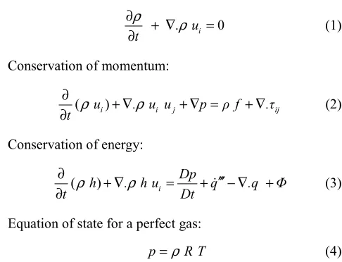
2.2. Flow Governing Equations
FDS solves numerically a form of the Navier-Stokes equations appropriate for low-speed; thermally-driven flow with an emphasis on smoke and heat transport from fires [16] as follows:
Conservation of mass:
. ui 0
t
ρ ρ
∂ + ∇ =
∂ (1)
Conservation of momentum:
( )ui . u u i j p ρ f .τij t ρ ρ
∂ + ∇ + ∇ = + ∇
∂ (2)
Conservation of energy:
( ) i
Dp
h . h u q .q Φ t ρ ρ Dt
∂ + ∇ = + ′′′− ∇ +
∂ ɺ (3)
Equation of state for a perfect gas:
p=ρ R T (4)
In terms of the mass fractions of the individual gaseous species, the mass conservation equation can be written as:
( Yi) . Y u i . Di Y mi i
t ρ ρ ρ
∂ + ∇ = ∇ ∇ + ′′′
∂ ɺ (5)
Where, ui is velocity in i-direction, i =1, 2, 3, ρ is fluid
density, f is summation of external forces, τij is shear stresses,
p is pressure, h is enthalpy, q ɺ′′′ is heat release rate per unit volume (HRRPUV), q is the heat transfer, Φ is any heat source, and T is the temperature. Yi is the mass fraction.
2.3. Large Eddy Simulations (LES) and Sub-Grid Scale Models
Large eddy simulation resolves large scales of the flow field solution allowing better fidelity than alternative approaches such as Reynolds-averaged Navier-Stokes (RANS) methods. It also models the smallest scales of the solution, rather than resolving them as direct numerical simulation (DNS) does.
Navier-Stokes equations are filtered, yielding the filtered incompressible continuity equation,
0 i i u x ∂ =
∂ (6)
and the filtered Navier-Stokes equations,
2
1
i i
i j ij
j i j j j
u p u
( u u ) ν
t x ρ x x x x τ
∂ + ∂ = − ∂ + ∂ ∂ − ∂
∂ ∂ ∂ ∂ ∂ ∂ (7)
Where, p is the filtered pressure field and
_____ __ __
-
ij u ui j u ui j
τ = is the subgrid-scale stress tensor. τij is
found by an eddy viscosity representation for small scales as [44]:
kk ij T
1
-2 3
___
ij Sij
τ = τ δ = υ (8)
Where, δij is the Kronecker's delta. To find τij , the Smagorinsky-Lilly sub-grid scale SGS model, which was developed by Smagorinsky [45] and used in the first LES
simulation by Deardorff [46], is used. The eddy viscosity is modeled as:
___ ___
2 2
2
T s g ij ij s g
ν =(C ∆ ) S S (C ∆ ) S= (9)
Where, ∆g is the filter width that is calculated as:
∆g = (∆x ∆y ∆z)1/3 (10)
∆x, ∆y and ∆z are the grid sizes in the three Cartesian
coordinates x, y and z, respectively. Cs is a modeling constant
that is problem-dependent. The magnitude of the large-scale strain rate tensor is defined as:
__ __ ___ 1 ( ) 2 j i ij j i u u S x x ∂ ∂ = +
∂ ∂ (11)
2.4. Combustion Model and Radiation Transport
FDS uses the mixture fraction model as the default combustion model [34]. The mixture fraction is a conserved scalar quantity. It is defined as the fraction of gas at a given point in the flow field that originated as fuel, as follows:
2
2
2
F O O
I
F O
sY (Y Y )
Z sY Y ∞ ∞ − − = + ; 2 2 O O F F
ν W s
ν W
= ; νF = 1 (12)
Where, Y is the mass fraction. Subscripts F and O2 refer to
fuel and oxygen, respectively. I F
Y is the fuel mass fraction in fuel stream. Superscript ∞ refers to "far away from the fire". ν is the stoichiometric coefficient. W is the molecular weight of gas. By design, mixture fraction varies from Z=1 in a region containing only fuel to Z=0 in regions (typically far away from the fire) where only ambient air with un-depleted
oxygen is present.
Radiative heat transfer is included in the model via the solution of the radiation transport equation for a non-scattering grey gas, and in some limited cases using a wide-band model. The equation is solved using a technique similar to finite-volume methods for convective transport, thus the name given to it is the Finite-Volume Method (FVM) [16].
3. Building Description and
Computational Aspects
3.1. Building Description
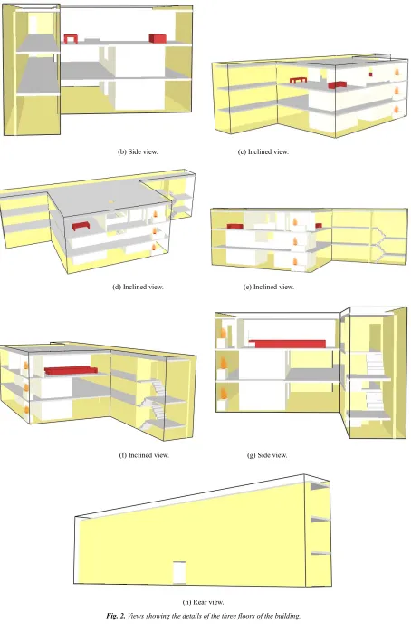
The present model is a three-story building, Fig. 2, with overall plan dimensions of about 41×17 m2. The overall height is 10 m. The offices and facility are concentrated in an area of 18×13 m2. A central-rectangular hollow-section extends from the first floor to the roof of the third floor with a cross-section of 4.4×3.2 m2. The main stairs are at the right of the building. There is a stair door at each floor, Figs. 2a,f,g, with dimensions of 2.3×0.9 m2. The main door (entrance) is located at the rear of the first floor, Fig. 2h, with dimensions of 2.7×2.4 m2. Some furniture samples appear in the third floor, Figs. 2a,f.
The source of fire is a wooden disk that was altered vertically between the three floors according to the fire case, Fig. 2a.
3.2. Computational Mesh and Domain
The governing equations were approximated on a rectilinear mesh (grid). A computational mesh of 202×85×50 cells was used. Thus, the cells were almost cubic with dimensions of 0.2×0.2×0.2 m3. Figure 3 shows some horizontal and vertical sections that illustrate the cells of the computational mesh. As can be seen, the mesh was very fine. Thus, the mesh was capable of capturing the features of both the flow and thermal fields.
As can be seen in Fig. 2, the computational domain was extended above the roof of the third floor and behind the building rear wall by about 0.5 m. These two extensions were intended to facilitate smoke exit from the upper vent (emergency opening) and the main door, respectively.
3.3. Boundary Conditions
3.4. Investigated Cases
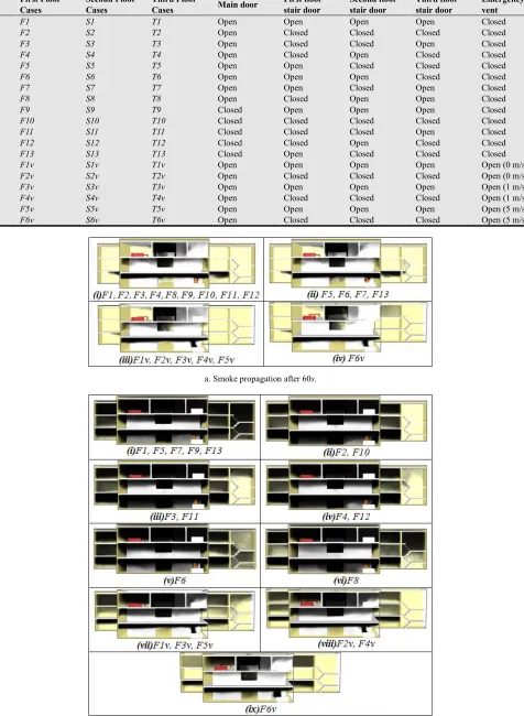
To investigate the effect of different possible real-life situations, fifty-seven cases were considered, table 1. These cases cover the location of fire source, the opening/closing of the stair doors and main door, and the operation of the emergency opening (vent).
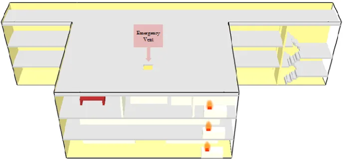
The actual situation of the building has no ceiling opening (vent). The authors of the present work propose an idea to reduce fire/smoke hazards by considering an active outlet vent in the ceiling of the third floor. This emergency vent operates automatically as the fire emerges depending on the signal of heat detectors. The vent is located in the geometric center of the central-rectangular hollow-section, Fig. 4a, with dimensions of 1.0×1.0 m2. The vent opens (activates) when the temperature reaches 40oC. For simplicity, a heat detector was placed just above the fire source, Fig. 4b. The heat detector is moved from the ceiling of one floor to another following the fire source. The vent is equipped by a fan that may operate at three different modes, namely: (i) no operation (zero velocity), (ii) outlet velocity of 1 m/s, (iii) outlet velocity of 5 m/s.
The cases of table 1 cover the fire location at the three floors. Symbols "F", "S", and "T" refer to the location of the fire source in the first, second, and third floors, respectively. Symbol "v" refers to vent operation. In the coming sections, the stair doors will be referred as "door-1", "door-2", and "door-3" for the first, second, and third floors, respectively.
4. Results and Discussions
The presentation of the results considers three main times after the fire ignition, namely: 60s (1 minute), 300s
(5 minutes), and final period. Actually, 60s was chosen as a suitable time for preliminary quick evacuation of the building after fire ignition with proper alarming. Moreover, 300s was considered as a suitable time for complete evacuation of the building. Final period is the time at which the smoke pattern reaches its steady (constant) shape within the building without further change with time.
4.1. Fire Source at the First Floor
Figure 5 shows the results of the smoke propagation for different cases. As it can be seen in Fig. 5a, after 60s of fire ignition, the smoke patterns are much similar to each others with small differences. Very small amount of smoke enters the stair area due to the open stair doors, Fig. 5a(ii). The opening of the emergency vent draws the smoke from the back walking corridor near the stair area, Figs. 5a(iii),5a(iv). Some smoke gathers in the back corridor near the closed
door-3 in case F6v, Fig. 5a(iv).
Figure 5b shows the smoke patterns after 300s. The smoke propagates in the three floors of the building especially the third floor for all cases without the emergency vent, Figs. 5b(i-vi). Smoke fills the stair area when door-1 is open, Fig. 5b(i). Of course, no smoke enters the stair area when all stair doors are closed, Fig. 5b(ii). The upper part of the stair area
is filled with smoke when door-3 is open, Fig. 5b(iii) while the rest of the stair area has no smoke. Small amount of smoke gathers at the upper part of the stair area when door-2
is open, Fig. 5b(iv). The stair area is partially filled with smoke when two of the stair doors are open, Figs. 5b(v,vi).
When the emergency vent is open, smoke is concentrated in the third floor, with low density in the other two floors, Figs. 5b(vii-ix). There is no smoke in the stair area when the three doors are closed, Figs 5b(viii,ix). When the fan of the emergency vent works with full capacity (5 m/s), the smoke density reduces in the third floor, Fig. 5b(ix).
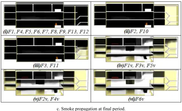
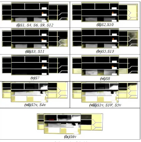
Figure 5c shows the smoke propagation at the final period. Table 2 shows the time in seconds of the final period for each case of Fig. 5c. The maximum period of 1800s occurs when
door-1 is closed (cases F8 and F12). It is clear that, by the final period, the smoke completely fills the three floors, Figs. 5c(i,ii). The upper part of the stair area is filled with smoke when door-3 is open, Figs. 5c(iii,iv). The stair area is free of smoke when the three stair doors are closed, Figs. 5c(ii,v,vi). Thus, some of the occupants can survive in the stair area until the fire fighters arrive to rescue them providing that the stair doors are well-protected against smoke leakage.
When the emergency vent is open, the smoke is drawn to the third floor, which has less smoke density comparing to other cases without the emergency vent, Figs. 5c(iv-vi). Even in the first floor, which has the fire source, the smoke is concentrated near the ceiling and thus leaving space for occupants to move with lowering their heads. When the fan of the emergency vent works with full capacity (5 m/s), the smoke density reduces in all floors, Fig. 5c(vi), especially the second floor which becomes almost empty of smoke. Hence, the occupants can survive in the second floor until being rescued.
As seen in Table 2, for all cases, the temperature distribution is almost the same with maximum temperature of 170oC, which is located in the fire area. Generally, temperature increase in the second and third floors is small. There is no temperature increase in the stair area. It is clear that the main door, whether open or closed, has a negligible effect on the smoke propagation.
4.2. Fire Source at the Second Floor
Figure 6 shows the results of the smoke propagation for different cases. Generally, as it can be seen in Fig. 6a, after 60s of fire ignition, similar behavior to that of Fig.5a is noticed. There are small differences between the smoke patterns. Very small amount of smoke enters the stair area due to the open stair doors, Fig. 6a(ii). The opening of the emergency vent draws the smoke from the back walking corridor near the stair area, Figs. 6a(iii,iv). Some smoke gathers in the back corridor near the closed door-3 in case
S6v, Fig. 6a(iv).
enters the stair area when all stair doors are closed, Fig. 6b(ii). The upper part of the stair area is filled with smoke when
door-3 is open, Fig. 6b(iii) while the rest of the stair area has no smoke.
When the emergency vent is open, smoke is concentrated in the third floor, with no smoke at all in the first floor, Figs. 6b(v-vii). Smoke gathers in the upper part of the second floor below the ceiling. Thus, occupants can move in the second floor and leave to the first floor by lowering their heads. There is no smoke in the stair area when the three doors are closed, Figs. 6b(vi,vii). When the fan of the emergency vent works with full capacity (5 m/s) and all stair doors are closed, the smoke density reduces in the third floor, Fig. 6b(vii).
Figure 6c shows the smoke propagation at the final period. Table 3 shows the time in seconds of the final period for each case of Fig. 6c. The maximum period of 1800s occurs for almost all cases, without the emergency vent working, except case S7 (1300s) when the two doors; door-1 and door-3, are open. It is clear that, by the final period, the smoke completely fills the three floors, Figs. 6c(i-v). The only exception is case S8, when door-1 is closed, the smoke density in the first floor is low in the back corridor, Fig. 6c(vi). Thus, the first floor is a good resort for late evacuation when securing door-1. The stair area is free of smoke when the three stair doors are closed, Fig. 6c(ii).
When the emergency vent is open, the smoke is drawn to the third floor, which has less smoke density comparing to other cases without the emergency vent, Figs. 6c(vii-ix). Even in the second floor, which has the fire source, the smoke is concentrated near the ceiling and thus leaving space for occupants to move with lowering their heads. The worst case (S6v) happens when the three stair doors are closed, Fig. 6c(ix). Generally, it seems that the operating speed of the fan of the emergency vent has very low effect on the smoke density.
As seen in Table 3, for all cases, the temperature distribution is almost the same with maximum temperature of 170oC, which is located in the fire area. Generally, temperature increases considerably in the second floor with partial increase in the third floor. There is small temperature increase in the stair area. There is no temperature increase in the first floor. It is clear that the main door, whether open or closed, has a negligible effect on the smoke propagation.
4.3. Fire Source at the Third Floor
The results of this section reveal that temperature rises to very high values (around 1000oC), which leads to sudden flashover through the building. Moreover, the building structure starts to burn gradually, which may lead to a building collapse eventually. The operation of the emergency vent prevents completely this flashover. Thus, the cases are divided into two sections; one for flashover and the other for operation of the emergency vent.
4.3.1. Cases of Flashover
Whether or not "flashover" occurs during the course of a fire is one of the most important outcomes of a fire
calculation. Flashover is characterized by the rapid transition to fire behavior from localized burning source to the involvement of all combustibles in the enclosure. High radiation heat transfer levels from the original burning item, the flame and plume directly above it, and the hot smoke layer spreading across the ceiling are all considered to be responsible for the heating of the other items, leading to their ignition. Factors affecting flashover include enclosure size, ceiling and wall conductivity and flammability, and heat- and smoke-producing quality of enclosure contents [48].
In the present study, warning signs of flashover were noticed just before the actual occurrence of flashover. These signs include heat build-up and "rollover". Rollover means small, sporadic flashes of flame that appear near ceiling level or at the top open doorways of smoke-filled enclosures [48]. This section covers all the investigated cases (T1-T13) without the operation of the emergency vent. Figure 7 shows the smoke propagation due to the fire source in the third floor. After 60s, the smoke pattern is exactly the same for all cases, Fig. 7a. Smoke is concentrated in the upper portion of the third floor, while the other two floors are completely free of smoke. Just before flashover, Fig. 7b, the smoke completely fills the third floor. When the three stair doors are open or
door-1 and door-3 are open, smoke fills completely the stair area and sneaks partially to the first and second floors, Fig. 7b(i). When the three stair doors are closed or only one door is open, smoke fills completely the third floor, and partially the second floor, whereas the first floor is approximately free of smoke, Fig. 7b(ii). When door-3 is open, smoke partially fills the upper half of the stair area and the second floor, Fig. 7b(iii). It is noticed that, in all cases, the first floor is completely or partially free of smoke, which represents good resort for occupants to get out of the building through the main door.
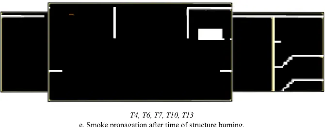
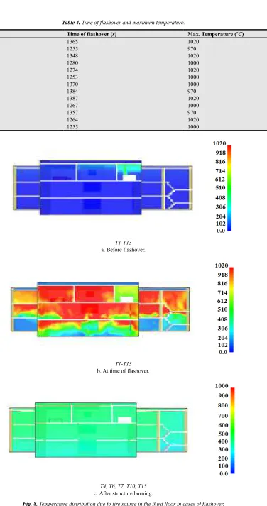
Figure 7c shows the smoke propagation at time of flashover for all cases (T1-T13). Both smoke and fire propagate in the whole building. Figure 7d shows the smoke propagation after time of flashover without structure burning for many cases. It is clear thus fire is decaying. Figure 7e illustrates the smoke propagation after time of structure burning for some cases (T4, T6, T7, T10, T13). Some parts of the structure are vanished due to flashover and high temperature rise. As can be seen in table 4, when the structure starts to burn, the maximum temperature is constant at 1000oC. It is clear from table 4 that the time of flashover is case-dependent and the maximum temperature is around 1000oC.
Figure 8 demonstrates the temperature distribution in cases of flashover. It is clear that sudden temperature rise occurs at the time of flashover in the whole building, Fig. 8b. However, in cases of structure burning, the temperature lowers after its sudden rise, Fig. 8c.
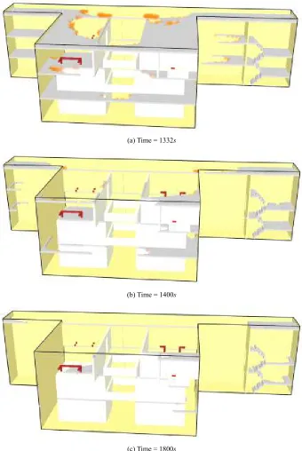
Figure 9 shows the development of the structure burning with time for case T6 as an example.
4.3.2. Cases of Operation of Emergency Vent
there is no flashover and structure burning. Figure 10 illustrates the patterns of smoke propagation with operation of the emergency vents (without flashover). After 60s, the smoke pattern is the same for all cases, Fig. 10a. Smoke is concentrated in the upper portion of the central area of the third floor. Smoke is sucked out the building through the emergency vent.
After 300s, the same pattern is kept as that after of 60s
when the fan of the emergency vent operates at full capacity (5 m/s) with the three stair doors are open, Fig. 10b(ii). In other cases, Figs. 10(i,iii,iv), the smoke propagates in other parts of the third floor but restricted to the upper portion. The two other floors are completely free of smoke.
After 1800s (the final period), the minimum density of the smoke is noticed when the fan of the emergency vent operates at full capacity (5 m/s), Figs. 10c(ii,v). Maximum smoke density is seen in the case (T2v) of the closed stair doors and the emergency vent is open with no fan working (0 m/s), Fig. 10c(iii). In all cases, Fig. 10c(i-v), the first and second floors as well as the stair area are completely free of smoke.
Fig. 11 demonstrates the temperature distribution in all the six cases. It is obvious that the operation of the emergency vent reduces the maximum temperature to 170oC which is much less and safer in comparison to the cases without
emergency vent when maximum temperatures becomes about 1000oC, table 4.
4.4. Smoke Exit of the Main Door
The smoke exit of the main door is an important factor in the evacuation plans. Table 5 illustrates the time at which the smoke starts to exit from the main door for all cases. As can be seen in table 5, the time of smoke exit, from the main door, increases considerably when the fire source moves from the first floor to the third floor. Considering the fire source in the first floor, the operation of the emergency vent approximately doubles the time required for the smoke to start exiting from the main door. However, for the fire source in the second or third floors, the operation of the emergency vent prevents completely the exit of smoke from the main door. Thus, the operation of the emergency vent helps greatly in the evacuation of the occupants from the main door of the building.
Figure 12 shows the progress of smoke exit of the main door with time of case F1 as an example. The smoke exiting from the main door is restricted to the upper portion of the main door till 180s (3 minutes). Thus, occupants can easily and safely leave the main door.
Fig. 1. Typical hot-smoke test layout using smoke canister [15].
(b) Side view. (c) Inclined view.
(d) Inclined view. (e) Inclined view.
(f) Inclined view. (g) Side view.
(h) Rear view.
Fig. 3. Views of the elements (cells) of the computational mesh.
(a) Top view showing the location of the proposed opening (emergency vent).
(b) Locations of the three heat detectors.
Table 1. Cases of the present study.
No. First Floor Cases
Second Floor Cases
Third Floor
Cases Main door
First floor stair door
Second floor stair door
Third floor stair door
Emergency vent
1 F1 S1 T1 Open Open Open Open Closed
2 F2 S2 T2 Open Closed Closed Closed Closed
3 F3 S3 T3 Open Closed Closed Open Closed
4 F4 S4 T4 Open Closed Open Closed Closed
5 F5 S5 T5 Open Open Closed Closed Closed
6 F6 S6 T6 Open Open Open Closed Closed
7 F7 S7 T7 Open Open Closed Open Closed
8 F8 S8 T8 Open Closed Open Open Closed
9 F9 S9 T9 Closed Open Open Open Closed
10 F10 S10 T10 Closed Closed Closed Closed Closed
11 F11 S11 T11 Closed Closed Closed Open Closed
12 F12 S12 T12 Closed Closed Open Closed Closed
13 F13 S13 T13 Closed Open Closed Closed Closed
14 F1v S1v T1v Open Open Open Open Open (0 m/s)
15 F2v S2v T2v Open Closed Closed Closed Open (0 m/s)
16 F3v S3v T3v Open Open Open Open Open (1 m/s)
17 F4v S4v T4v Open Closed Closed Closed Open (1 m/s)
18 F5v S5v T5v Open Open Open Open Open (5 m/s)
19 F6v S6v T6v Open Closed Closed Closed Open (5 m/s)
a. Smoke propagation after 60s.
c. Smoke propagation at final period.
Fig. 5. Views of the smoke propagation due to fire source in the first floor.
Table 2. Final period and maximum temperature due to fire source in the first floor for different cases.
Case Final time Maximum Temperature = 170oC
F7, F9, F13 900s
F10, F11 1000s
F1, F3, F5, F6, F2, F4, F1v, F3v, F5v,
F2v, F4v, F6v 1200s
F8, F12 1800s
a. Smoke propagation after 60s.
c. Smoke propagation at final period.
Fig. 6. Views of the smoke propagation due to fire source in the second floor.
Table 3. Final period and maximum temperature due to fire source in the second floor for different cases.
Case Final time Maximum Temperature = 170oC
S1v, S3V, S5v, S2v, S4v, S6v 1200s
S7 1300s
S1, S4, S6, S9, S12, S2,S10, S3, S11,
T1,T2, T3, T4, T5, T6, T7, T8, T9, T10, T11, T12, T13
a. Smoke propagation after 60s.
b. Smoke propagation before flashover.
T1, T2, T3, T4, T5, T6, T7, T8, T9, T10, T11, T12, T13
c. Smoke propagation at time of flashover.
T1, T2, T3, T5, T8, T9, T11, T12
d. Smoke propagation after time of flashover without structure burning.
T4, T6, T7, T10, T13
e. Smoke propagation after time of structure burning.
Table 4. Time of flashover and maximum temperature.
Case Time of flashover (s) Max. Temperature (oC)
T1 1365 1020
T2 1255 970
T3 1348 1020
T4 1280 1000
T5 1274 1020
T6 1253 1000
T7 1370 1000
T8 1384 970
T9 1387 1020
T10 1267 1000
T11 1357 970
T12 1264 1020
T13 1255 1000
T1-T13
a. Before flashover.
T1-T13
b. At time of flashover.
T4, T6, T7, T10, T13
c. After structure burning.
(a) Time = 1332s
(b) Time = 1400s
(c) Time = 1800s
Fig. 9. Views of the structure burning due to fire source in the third floor at different time periods (Case T6 as an example).
T1v, T2v, T3v, T4v, T5v, T6v
b. Smoke propagation after 300s.
c. Smoke propagation at final period (1800s).
Fig. 10. Views of the smoke propagation due to fire source in the third floor without flashover (operation of emergency vent).
T1v, T2v, T3v, T4v, T5v, T6v (Max Temperature = 170oC)
Table 5. Time of smoke exit out of the main door.
First floor cases Time (s) Second floor cases Time (s) Third floor cases Time (s)
F1 30 S1 240 T1 1125
F2 30 S2 270 T2 1250
F3 30 S3 220 T3 1345
F4 30 S4 220 T4 1272
F5 30 S5 215 T5 1268
F6 30 S6 485 T6 1247
F7 30 S7 230 T7 1357
F8 30 S8 675 T8 1382
F9 Closed S9 Closed T9 Closed
F10 Closed S10 Closed T10 Closed
F11 Closed S11 Closed T11 Closed
F12 Closed S12 Closed T12 Closed
F13 Closed S13 Closed T13 Closed
F1v 60 S1v No exit T1v No exit
F2v 60 S2v No exit T2v No exit
F3v 57 S3v No exit T3v No exit
F4v 57 S4v No exit T4v No exit
F5v 57 S5v No exit T5v No exit
F6v 57 S6v No exit T6v No exit
Fig. 12. Progress of smoke exit of the main door with time (Case F1 as an example).
5. Conclusions
Based on the above results and discussions, the following concluding points can be stated:
(i) Temperature may rise to unexpected very high levels and flashover occurs when the smoke does not find its way out of the building. This is typically happened in the present study for the cases of fire source in the third floor. Depending on the material of the structure, this may lead to structure burning and/or building collapse.
(ii) Distribution of temperature and its maximum value are dependent on the fire location and the outlet openings of the smoke.
(iii) Emergency vents in the roof of the top floor, which operate in time of fire based on the signal of heat/smoke detectors, play an outstanding job in sucking the smoke outside the building. Thus, flashover is prevented and evacuation of the occupants becomes much easier and safer.
(iv) In some of the investigated cases, the emergency
vents may cause the first and/or the second floors to be fully or partially free of smoke for a relatively large period of time (20 or 30 minutes).
(v) Naturally, the increase of the speed of the fan of the emergency vent draws more smoke out of the building. However, in certain cases, just the vent opening without fan operation helps greatly in sucking the smoke out of the building.
(vi) The location of the fire source, relative to the building floors, affects significantly the smoke propagation and density.
(vii) The inner openings between different floors facilitate the smoke propagation from one floor to another. This situation is very tricky to the occupants and may cause serious injuries.
(viii)The condition of the stair doors; open or closed, has an important effect on the smoke propagation. Smoke may move from the upper floor to a lower floor through the open doors of the stair area.
of time. Thus, the stair area becomes a good resort for occupants until the arrival of fire fighters to rescue them providing that the stair doors are well-insulated against smoke leakage.
(x) Generally, the condition of the main door; open or closed, has a little effect on the smoke propagation. However, it is essential to study the smoke movement out of it for proper evacuation plans.
(xi) Occupants should be trained to obey the emergency and evacuation plans especially lowering their heads below the smoke layer to survive. In many of the investigated cases, the smoke is constrained to the upper portion of the floor just below the ceiling.
Acknowledgement
The authors would like to acknowledge Engs. B. S. Qattan, O. S. Yamani, H. H. Bahha, S. A. Gubali, B. A. Al-Sobhi, and N. M. Al-Harbi for their efforts to complete the present study.
Nomenclature
Cs = modeling constant.
F = summation of external forces.
H = enthalpy.
Q = heat transfer.
q ɺ′′′ = heat release rate per unit volume (HRRPUV).
P = pressure.
p = filtered pressure field.
___
ij
S = magnitude of the large-scale strain rate tensor.
T = temperature.
ui = velocity in i-direction, i =1, 2, 3.
i j
u u = nonlinear filtered advection term.
W = molecular weight of gas.
Y = mass fraction. I
F
Y = fuel mass fraction in fuel stream.
Z = mixture fraction.
Greek
δij = Kronecker's delta.
∆g = filter width.
∆x, ∆y and
∆z
= grid sizes in the Cartesian coordinates x, y
and z, respectively.
Φ = any heat source.
ν = stoichiometric coefficient. νT = Turbulent eddy viscosity.
ρ = fluid density.
τij = subgrid-scale stress tensor.
Superscripts and Subscripts
∞ = refers to "far away from the fire".F = refers to "fuel".
O2 = refers to "oxygen".
Abbreviations
ASTM = American Society for Testing and Materials.
BFST = Bureau of Fire Standards and Training.
CFD = Computational Fluid Dynamics.
DNS = Direct Numerical Simulation.
FDS = Fire Dynamic Simulator.
FPA = Fire Protection Association Australia.
FVM = Finite-Volume Method.
HRRPUV = Heat Release Rate per Unit Volume.
LES = Large Eddy Simulation.
NFPA = National Fire Protection Association.
NIST = National Institute of Standards and Technologies.
RANS = Reynolds-Averaged Navier-Stokes.
SBI = Single Burning Item.
SGS = Sub-Grid Scale.
References
[1] W. Men, K. B. Mcgrattan, and H. R. Baum, "Large Eddy Simulations of Fire-Driven Flows", ASME National Heat Transfer Conference, Vol. 2, 1995.
[2] A. Kashef, N. Bénichou, G. Lougheed, and A. Debs, "Computational Fluid Dynamics Simulations of in-Situ Fire Tests in Road Tunnels", 5th International Conference-Tunnels Fires, London, UK, pp. 185-196, Oct. 25-27, 2004.
[3] Y. Xin, J. P. Gore, K. B. McGrattan, R. G. Rehm, and H. R. Baum, "Fire Dynamics Simulation of a Turbulent Buoyant Flame Using a Mixture-Fraction-Based Combustion Model", Combustion and Flame J., Vol. 141, pp. 329-335, 2005. [4] W. Jahn, G. Rein, and J. L. Torero, "The Effect of Model
Parameters on the Simulation of Fire Dynamics", Fire Safety Science, Vol. 9, pp. 1341-1352, 2008.
[5] Y. Huo, Y. Gao1, and W. Chow, "Locations of Diffusers on Air Flow Field in an Office," The Seventh Asia-Pacific Conference on Wind Engineering, Taipei, Taiwan, November 8-12, 2009.
[6] L. Razdolsky, "Mathematical Modeling of Fire Dynamics," Proceedings of the World Congress on Engineering 2009, London, U.K., Vol. II, July 1 - 3, 2009.
[7] H. Cheng, and G. V. Hadjisophocleous, "Dynamic Modeling of Fire Spread in Building", Fire Safety Journal, Vol. 46, No. 4, pp. 211-224, 2011.
[8] D. Ling, and K. Kan, "Numerical Simulations on Fire and Analysis of the Spread Characteristics of Smoke in Supermarket", In Advanced Research on Computer Education, Simulation and Modeling, pp. 7-13, Springer Berlin Heidelberg, 2011.
[9] P. Yang, X. Tan, and W. Xin, "Experimental Study and Numerical Simulation for a Storehouse Fire Accident", Building and Environment, Vol. 46, No. 7, pp. 1445-1459, 2011. [10] C. Zhang, and G. Q. Li, "Fire Dynamic Simulation on Thermal
[11] R. Sun, Z. Huang, and I. W. Burgess, "Progressive Collapse Analysis of Steel Structures under Fire Conditions", Engineering Structures, Vol. 34, pp. 400-413, 2012.
[12] A. H. Wu, and L. C. Chen, "3D Spatial Information for Fire-fighting Search and Rescue Route Analysis within Buildings", Fire Safety Journal, Vol. 48, pp. 21-29, 2012.
[13] A. Agarwal, and A. H. Varma, "Fire Induced Progressive Collapse of Steel Building Structures: The Role of Interior Gravity Columns", Engineering Structures, Vol. 58, pp. 129-140, 2014.
[14] M. He, and Y. Jiang, "Use FDS to Assess Effectiveness of Air Sampling-Type Detector for Large Open Spaces Protection", Vision Fire & Security, 2005.
[15] A. Webb, "FDS Modelling of Hot Smoke Testing, Cinema and Airport Concourse", Thesis of Master of Science, The Faculty of the Worcester Polytechnic Institute, USA, 2006.
[16] P. Smardz, "Validation of Fire Dynamics Simulator (FDS) for Forced and Natural Convection Flows", Master of Science in Fire Safety Engineering, University of Ulster, 2006.
[17] R. Sun, M. A. Jenkins, S. K. Krueger, W. Mell, and J. J. Charney, "An Evaluation of Fire-Plume Properties Simulated with the Fire Dynamics Simulator (FDS) and the Clark Coupled Wildfire Model," Can. J. for Res., Vol. 36, pp. 2894-2908, 2006.
[18] P. Coyle, and V. Novozhilov, "Further Validation of Fire Dynamics Simulator Using Smoke Management Studies", International Journal on Engineering Performance-Based Fire Codes, Vol. 9, No. 1, pp.7-30, 2007.
[19] J. Zhang, M. Delichatsios, and M. Colobert, "Assessment of Fire Dynamics Simulator for Heat Flux and Flame Heights Predictions from Fires in SBI Tests", Fire Technology, Vol. 46, pp. 291–306, 2010.
[20] N. Wu, R. Yang, and H. Zhang, "A Distributed Method for Predicting Building Fires Based on a Two-Layer Zone Model", ASME 2013 International Mechanical Engineering Congress and Exposition, 2013.
[21] X. T. Zhang, and S. L. Wang, "Numerical Simulation of Smoke Movement in Vertical Shafts during a High-Rise Building Fire", Applied Mechanics and Materials, Vol. 438, pp. 1824-1829, 2013.
[22] Y. Jiang, G. Rein, S. Welch, and A. Usmani, "Modeling Fire-Induced Radiative Heat Transfer in Smoke-Filled Structural Cavities", International Journal of Thermal Sciences, Vol. 66, pp. 24-33, 2013.
[23] Y. Yu, Y. Y. Chu, and D. Liang, "Study on Smoke Control Strategy in a High-rise Building Fire", Procedia Engineering, Vol. 71, pp. 145-152, 2014.
[24] X. Zhang, S. Wang, and J. Wang, "Numerical Simulation of Smoke Movement in Vertical Shafts during High-Rise Fires Using a Modified Network Model", Journal of Chemical & Pharmaceutical Research, Vol. 6, No. 6, 2014.
[25] S. Bae, H. J. Shin, and H. S. Ryou, "Development of CAU_USCOP, A Network-Based Unsteady Smoke Simulation Program for High-Rise Buildings. Building Simulation, Vol. 7, No. 5, pp. 503-510, 2014.
[26] F. Tingyong, X. Jun, Y. Jufen, and W. Bangben, "Study of Building Fire Evacuation Based on Continuous Model of FDS & EVAC", In Computer Distributed Control and Intelligent Environmental Monitoring (CDCIEM), IEEE Conference, pp. 1331-1334, 2011.
[27] F. Tang, and A. Ren, "GIS-based 3D evacuation simulation for indoor fire", Building and Environment, Vol. 49, pp. 193-202, 2012.
[28] L. Zhang, Y. Wang, H. Shi, and L. Zhang, "Modeling and analyzing 3D complex building interiors for effective evacuation simulations", Fire Safety Journal, Vol. 53, pp. 1-12, 2012.
[29] http://www.fire.nist.gov/fds/, http://www.nist.gov/index.html [30] A. F. Abdel-Gawad, and H. A. Ghulman, "Fire Dynamics
Simulation of Large Multi-story Buildings, Case Study: Umm Al-Qura University Campus", International Conference on Energy and Environment 2013 (ICEE2013), Universiti Tenaga Nasional, Putrajaya Campus, Selangor, Malaysia, 5-6 March 2013. [Institute of Physics (IOP) Conference Series: Earth and Environmental Science, Vol. 16, issue 1, 2013, doi:10.1088/1755-1315/16/1/012040].
[31] G. P. Forney, Smokeview (Version 5)-A Tool for Visualizing Fire Dynamics Simulation Data - Volume I: User’s Guide, NIST Special Publication 1017-1, 2010.
[32] G. P. Forney, Smokeview (Version 5)-A Tool for Visualizing Fire Dynamics Simulation Data - Volume II: Technical Reference Guide, NIST Special Publication 1017-2, 2010. [33] G. P. Forney, Smokeview (Version 5)-A Tool for Visualizing
Fire Dynamics Simulation Data - Volume III: Verification Guide, NIST Special Publication 1017-3, 2010.
[34] K. McGrattan, S. Hostikka, J. Floyd, H. Baum, R. Rehm, W. Mell, and R. McDermott, Fire Dynamics Simulator (Version 5)-Technical Reference Guide-Volume 1: Mathematical Model, NIST Special Publication 1018-5, 2010.
[35] K. McGrattan, R. McDermott, S. Hostikka, and J. Floyd, Fire Dynamics Simulator (Version 5)-User’s Guide, NIST Special Publication 1019-5, 2010.
[36] K. McGrattan, S. Hostikka, J. Floyd, and B. Klein, Fire Dynamics Simulator (Version 5) Technical Reference Guide -Volume 3: Validation, NIST Special Publication 1018-5, 2010. [37] National Fire Protection Association (NFPA): The American
authority on fire, electrical, and building safety: http://www.nfpa.org
[38] British Standards: http://shop.bsigroup.com
[39] The Bureau of Fire Standards and Training (BFST), Division
of State Fire Marshal, Florida,
USA:http://www.myfloridacfo.com/sfm/bfst/bfst_index.htm [40] Fire Protection Association Australia (FPA), Australia:
http://www.fpaa.com.au
[41] ASTM International, formerly known as the American Society for Testing and Materials (ASTM), USA: http://www.astm.org/Standards/fire-and-flammability-standards.html
[43] Fire Commissioner of Canada Standards: http://www.hrsdc.gc.ca/eng/labour/fire_protection/policies_sta ndards
[44] A. Leonard, "Energy Cascade in Large-Eddy Simulations of Turbulent Fluid Flows", Advances in Geophysics A, Vol. 18, pp. 237–248, 1974.
[45] J. Smagorinsky, "General Circulation Experiments with the Primitive Equations", Monthly Weather Review, Vol. 91 (3), pp. 99–164, 1963.
[46] J. Deardorff, "A Numerical Study of Three-Dimensional Turbulent Channel Flow at Large Reynolds Numbers", Journal of Fluid Mechanics, Vol. 41 (2), pp. 453–480, 1970.
[47] Z.-C. Grigoraş, and D. Diaconu-Şotropa, "Establishing the Design Fire Parameters for Buildings", Bul. Inst. Polit. Iaşi, t. LIX (LXIII), f. 5, pp. 133-141, 2013.
![Fig. 1. Typical hot-smoke test layout using smoke canister [15].](https://thumb-us.123doks.com/thumbv2/123dok_us/8484422.1714837/6.595.153.444.382.600/fig-typical-smoke-test-layout-using-smoke-canister.webp)