ISSN: 2231-5381
http://www.ijettjournal.org
Page 630
Implementing MOD bus and CAN bus Protocol
Conversion Interface
Umesh Goyal
1, Gaurav Khurana
2 1M.E., Electronics & Electrical Communications Department, PEC University of Technology, India 2
M.E., Electronics & Electrical Communications Department, PEC University of Technology, India
Abstract—A number of field buses are available to exchange the serial data among one or more controllers and a number of field devices that are communicating with each other. However, field bus standards are not uniform at present, which brings many difficulties in system design, as different equipments from different manufacturers follow different standards. For a reliable system design there is a need of efficient communication interface to make the communication possible. CAN bus and Modbus are two most common field buses used in industrial control equipments. This paper highlights the basics of these buses and also explain the designing of CAN bus and Modbus protocol conversion interface. A complete hardware and software design detail is also provided in this paper.
Index Terms
—
Modbus, CAN bus, CANopen, PIC, MicrocontrollerI. INTRODUCTION
Any Embedded system is generally consisting of one or more micro-processors or micro-controller and a number of peripherals IC’s like EEPROM, Real time clock (RTC), watchdog timer and sensors etc. In communication system design, a key challenge is the ability to make different components from different manufactures communicates with each other. Many serial communication protocols like RS-232/RS-485, I2C, SPI, Modbus and CAN bus etc. compete for use in embedded systems. All these protocols have their own advantages and limitations. Generally, different manufactures follow different protocols and standards. This makes the system integration task very difficult. So there must be some means to make this task easier. Protocol conversion interface is one of the possible solutions for this problem. CAN bus and Modbus are two most common fieldbus protocol used in industrial control systems.
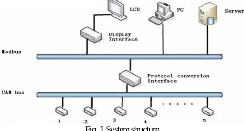
Fig. 1 System structure
This paper implement a CAN bus to Modbus protocol conversion interface. Both sides of serial connections are isolated galvanically to provide perfect protection against lightning, surges, high voltage transients. After the brief introduction of each protocol, this paper briefly explain the hardware and software design of CAN bus to Modbus protocol conversion interface. Fig 1 describes the basic overview of the system i.e. how different devices are connected in the system [1].
II. PROTOCOL OVERVIEW
A. MOD bus
Modbus is a serial communications protocol published by Modicon in 1979. MODBUS Protocol defines a standard message structure with universal recognition and usage regardless of the type of networks over which any two devices communicate. It is a master-slave communication protocol. It describes the process a master uses to request an access to slave, and how the slave will respond to these requests, and how errors will be detected and reported. Master can initiate transactions (called ‘queries’) and slave respond by supplying the requested data to the master, or by taking the action requested in the query. The master can address individual slaves, or can initiate a broadcast message to all slaves. Slaves return a message (called a ‘response’) to queries that are addressed to them individually. Responses are not returned to broadcast queries from the master. Fig 2 describes the Master-slave query response cycle.
ISSN: 2231-5381
http://www.ijettjournal.org
Page 631
Master’s query consists of slave device (or broadcast) address, a function code defining the requested action, any data to be sent, and an error checking field. The slave’s response contains fields confirming the action taken, any data to be returned, and an error–checking field. Table I shows the PDU and ADU of Modbus protocol.
Table I Modbus data format
Protocol data unit (PDU ) Application Data unit(ADU)
1 byte 1 byte Variable 2 bytes Address
field
Function field
Data field Error checking
field
If the slave makes a normal response, the function code in the response is an echo of the function code in the query. If an error occurred in receipt of the message, or if the slave is unable to perform the requested action, the slave will construct an error message by modifying the function code (set the MSB of function code) to indicate that the response is an error response, and the data bytes contain a code that describes the error.
Modbus protocol can be established in two kinds of transmission mode: ASCII mode or RTU mode. In ASCII mode, each 8–bit byte in a message is sent as two ASCII characters. In RTU mode, each 8–bit byte in a message contains two 4–bit hexadecimal characters. The main advantage of RTU mode is that its greater character density allows better data throughput than ASCII for the same baud rate. Modbus protocol has the parity check, besides, the ASCII mode uses the LRC check, and the RTU mode uses 16 CRC check.
Table II is a comparison between ASCII mode and RTU mode[2].
Table II
Comparison of ASCII and RTU mode
Mode Beginning
marks
Ending
marks
Check Transmission
efficiency
ASCII
: (colon)
CR,LF
LRC
low
RTU
Non
Non
CRC
High
According to Table I, the data transmission rate of ASCII mode is a little lower than RTU mode. So, when need to send large data, user always uses RTU mode. The standard Modbus protocol is to use a RS-232C compatible serial interface, which defines the port pin, cable, digital signal transmission baud rate, parity.
B. CAN bus(Controller Area Network)
The CAN bus was developed by German automotive system supplier Robert Bosch in mid-1980’s for automotive applications in automobile systems. CAN is an International Standardization Organization (ISO) defined serial communications bus originally developed for the automotive industry to replace the complex wiring harness with a two-wire bus. The specification calls for high immunity to electrical interference and the ability to self-diagnose and repair data errors. These features have led to can’s popularity in a variety of industries including building automation, medical, and manufacturing.
The can communications protocol, iso-11898, describes how information is passed between devices on a network and conforms to the open systems interconnection (OSI) model that is defined in terms of layers. Actual communication between devices connected by the physical medium is defined by the physical layer of the model [3]. The ISO 11898 architecture defines the lowest two layers of the seven layer OSI/ISO model as the data-link layer and physical layer as shown in figure 3.
Fig. 3 The layered ISO standard 11898 architecture
ISSN: 2231-5381
http://www.ijettjournal.org
Page 632
Fig.4 Arbitration on a CAN Bus
A CANopen device can be logically structured in three parts. One part provides the CAN interface and another part provides the device's application, which controls e.g. the Input/output (I/O) lines of the device in case of an I/O module. The interface between the application and the CAN-interface is implemented in the object dictionary [4]. The object dictionary is unique for any CANopen device. It is comparable to a parameter list and offers the access to the supported configuration- and process data. To gain access to the object dictionary, each CANopen device has to implement a CANopen protocol stack [5]. This CANopen protocol stack is software, which is usually implemented on the same micro-controller that is used by the device's application software. The internal device structure is shown in fig 5.
Fig. 5 Internal Device Structure
III.IMPLEMENTATION A. Hardware design
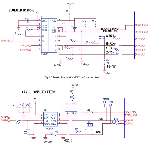
Design of this CAN bus to MODBUS protocol conversion interface is done by using PIC32MX-XXX series microcontroller. This series of microcontrollers has 6 UART and 2 CAN modules. These on chip modules are appropriate of the design of protocol conversion interface. This design also included a CAN trans-receiver (ISO-1050) and As the MODBUS using the RS-485 serial interface, this design uses RS485 trans-receiver (ISO-3050). The ISO-1050 is an isolated CAN transceiver that meets or exceeds the specifications of the ISO-11898 standard [6] and ISO-3080 is an isolated full-duplex differential line drivers and receivers. This CAN transceiver provides differential transmit capability to the bus and differential receive capability to a CAN controller at signalling rates up to 1 megabit per second (Mbps). The internal oscillator circuit of PIC32 microcontroller is used to generate the system clock. This system is working on a high frequency of 32 MHz. Block diagram of protocol conversion interface is shown in figure 8.
ISSN: 2231-5381
http://www.ijettjournal.org
Page 633
J1 1 2 RS485_1_B ISOLATED SUPPLY C1 ISOLATED GND +5V_ISOISOLATED RS485-1
+5V R13 C3 R10A-RX+
R14 12K RS485_RX1B-RX-RS485_EN1 GISO_1
Y-TX+
RS485_TX1 U1 ISO3080 GND1 2 GND1 7 GND1 8 R 3 RE 4 DE 5 GND2 15 Z 12 Y 11 B 13 A 14 D 6 VCC1 1 VCC2 16 GND2 9 GND2 10Z-TX-R1 R8 12K GISO_1 C2 R12 R6 R11 R9
PD-'B'
R5 R3 R4 R2 R7 ISO_GND RS485_1_VISO RS485_1_Y RS485_1_GISO RS485_1_Z RS485_1_AFig. 6 Schematic Diagram for MOD bus Communication
R19 +5V CANL1 CANRX1 CANH1 CANH1 R17 CANL1 R21 0E R15 0E U2 IS01050 VCC2 8 CANH 7 CANL 6 GND2 5 VCC1 1 RXD 2 TXD 3 GND1 4 C6 C7 C5 C4 R20 C8 C9 CANTX1 R16 GISO_3 +5V_ISO
CAN-1 COMMUNICATION
ISO_GND CAN_H1 CAN1_GISO R18 CAN_L1 C10 CAN1_VISO J2 1 2ISSN: 2231-5381
http://www.ijettjournal.org
Page 634
CAN1_GISO
CAN_L1 CAN_H1 CAN1_VISO
RS 485
FOR MODBUS
CAN
P
I
C
3
2
M
X
M
i
c
r
o
c
o
n
t
r
o
l
l
e
r
ISO1050
RS485_EN1
RS485_RX1
RS485_TX1
MODBUS
CANBUS
RS485_1_VISO
RS485_1_GISO
RS485_1_Z RS485_1_Y
RS485_1_A
RS485_1_B
CANRX1
CANTX1
Fig. 8 Conversion Interface
B. Software design
This protocol conversion interface is working on Master-slave technique and only master can initiate the communication. Here CAN bus is chosen as the master and MODBUS as slave i.e. only CAN bus can start the communication and MODBUS devices can respond according to request made by the master. The whole communication is controlled by an event driven interrupt. Whenever CAN master want to communicate with a device connected over the MODBUS then it generate an interrupt. On receiving this interrupt, CPU enters into an interrupt service routine (ISR). In this routine, CPU receive the data from CAN master and checks the integrity of the data using CRC check. If data is found to be valid then program enters into a routine which convert this data into MODBUS format. This format contain slave address, function code, data field and CRC field. Thus this conversion interface encapsulates the data in Modbus protocol format to send to the Modbus site. Now slave device receives the data and responds back with the response data. Conversion interface receives this response data. After receiving message conversion interface analyses data, and then convert to CAN protocol format, send to master. Note that, due to the length of CAN bus data transmission up to 8 bytes, if Modbus protocol transmits data is longer than 8 bytes it will send data many times.
C. Flow Chart
The flow chart as shown in figure 9 described the working of the system i.e. how the data from one bus is sent to other bus with their data formats changed using PIC32MX microcontroller.
ISSN: 2231-5381
http://www.ijettjournal.org
Page 635
IV.RESULTS
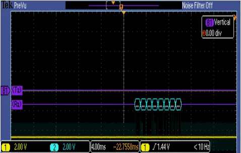
By using the hardware and software logic as explained above CAN bus to Modbus protocol conversion interface is implemented and results are shown in figure 10 and 11. Figure 10 shows the data sent by CAN bus device to the protocol conversion interface and figure 11 shows the data sent by protocol conversion interface to Modbus device.
Fig. 10 data from CAN bus to conversion interface
Fig. 11 data from conversion interface to Modbus.
REFERENCES
[1] Guohuan Lou, Zhang Hao, Zhao Wei, “Research on Designing Method of CAN Bus and Modbus Protocol Conversion Interface”. In Proceeding of 2009 International Conference on Future Bio-Medical Information Engineering.
[2] Modbus Application Protocol Specification V1.1b, Modbus-IDA, December 2006, pp. 1-51, [Online] available at
http://www.modbus-IDA.org.
[3] H. Boterenbrood, “Canopen high-level protocol for CAN-bus,” NIKHEF, Amsterdam, March 20, 2000.
[4] Rao Yuntao. Principle and Application of CAN field bus technology.
[5] Rauchhaupt L., System and Device Architecture of a Radio Based Fieldbus -The RFieldbus System[C], In Proceeding of the 2002 IEEE International Workshop on Factoty Communication Systems, 2002,8.pp.193-202
[6] ISO-IS 11898 Road vehicles - Interchange of digital information - Controller Area Network (CAN) for high speed communication, 1993
Umesh Goyal, born on 18 July 1990 at Moga, Punjab, India. He is currently pursuing Masters in Engineering in Electronics field from PEC University of Technology, Chandigarh, India. His Masters in Engineering will be completed by June, 2013. He has completed his Bachelors of Technology in Electronics and Communication Engineering from Chitkara Institute of Engineering & Technology, Punjab, India in year-2011. The major field of his work is related to Electronic Embedded Systems, Digital Signal Processing, and System Design.
Gaurav Khurana, born on 07 September 1987 at Ambala Cantt, Haryana, India. He is currently pursuing Masters in Engineering in Electronics field from PEC University of Technology, Chandigarh, India. His Masters in Engineering will be completed by June, 2013. He has completed his Bachelors of Technology in Electronics and Communication Engineering from Ambala college of Engineering & Applied research, mithapur, Haryana, India in year-2009. The major field of his work is related to Microcontroller and Embedded Systems, Digital Signal Processing and digital communication.
![Table II is a comparison between ASCII mode and RTU mode[2].](https://thumb-us.123doks.com/thumbv2/123dok_us/8644689.1725367/2.595.324.540.344.519/table-ii-comparison-ascii-mode-rtu-mode.webp)