RESEARCH ARTICLE
Energy Efficient Routing (EER) For Reducing
Congestion and Time Delay in Wireless Sensor
Network
A. Anuba Merlyn
Colombo,Srilanka.
[email protected]
A. Anuja Merlyn
System Admin, St. Xavier’s Bank, Nagercoil, India.
[email protected]
Abstract – A Wireless Sensor Network (WSN) has sensor nodes which highly scalable and limited storage capability nodes. In the network, the nodes are in distributed manner and autonomous devices. The sensor node can communicate the information directly or indirectly. In WSN, the packets should be routed from source to destination within the limited power storage. The sensor nodes of WSN are highly mobile and based on the dynamic scenarios in the routing path and the network topology change frequently. A node in the routing path should be aware of the information regarding the nearest node. In traditional routing protocols, every node in the network exchanges periodic one-hop beacons. Beacons are short messages send periodically to indicate the neighbor nodes about their identification and position in the network. In the existing approach, some problems may occur during the data forwarding. Hence to overcome those problems Energy Efficient Routing (EER) approach is proposed in this paper. In the proposed modelling, the new algorithm named Discrete Delay Function (DDF) is introduced. In that algorithm, RTS/CTS message handshaking mechanism is used for data forwarding. By using this mechanism, the existing approaches’ limitations can be reduced. Simulation results show that EER scheme significantly outperforms existing protocols in wireless sensor networks with highly dynamic network topologies.
Index Terms – Discrete Delay Function, Energy Efficient Routing, Geographic Adaptive Fidelity, Geographic Energy Aware Routing.
1. INTRODUCTION
A WSN is a collection of sensors interconnected by wireless communication channels. Each sensor node is a small device that is capable of collecting data from its nearly surrounding area. With this data simple computations are carried out and communicate with other sensor nodes or controlling authorities in the network. In ad-hoc network various routing protocols have been proposed and because of scalability, these protocols are not precisely suitable for WSN. WSN consists
of large number of low power sensor nodes, operated in harsh environment with limited computational and sensing capabilities. Compared to the traditional sensor networks, WSN provides a flexible proposition in terms of deployment and multiple functionalities. The compact physical nature of the WSN permits a large number of sensor nodes to be randomly placed in inaccessible terrains. Also, the nodes in the WSN are capable of performing functions like data processing and routing.
1.1. Routing Methods In Wireless Sensor Network
For the routing purpose, many routing protocols are used for data forwarding. There are two types of WSN routing protocols according to their structure and their operation. They are, Network Structure and Protocol Operation. According to the network architecture the protocols are analyzed. Those protocols are, Flat Network Routing, Hierarchical Network Routing, and Location Based Routing. From these routing protocols, Location Based Routing protocol is the best one because of finding the location of the nodes. The sensor nodes find by their IP addresses easily. In the Location Based Routing, Geographic type of protocol is used for routing in geometric type of network. Geographic Adaptive Fidelity (GAF) is the most known algorithm for routing in the Location Based Routing. This is energy aware protocol algorithm. According to this algorithm, the network area is first divided into fixed zones and forms a virtual grid. Inside each zone, nodes collaborate with each other to play different roles. This network is called Geometric Network. 1.2. Existing System
RESEARCH ARTICLE
oblivious routing mechanism are Congestion and Energy Lose. To overcome those problems, the system developed by using Discrete Delay Function (DDF) is used to overcome those problems.
2. RELATED WORK 2.1. Existing System Model
Jamal N. AL-Karaki et.al, (2004) [1] proposed, the routing challenges and existing routing protocols. They noted the routing challenges are, Node deployment, Energy Consumption without Losing Accuracy, Data Reporting Method, Node/Link Heterogeneity, Fault Tolerance, Scalability, Network Dynamics, Transmission Media, Connectivity, Coverage, Data Aggregation, Quality of Service and the Routing Protocols are Flat based routing protocols, Hierarchical based routing protocols, Location based routing protocol and so on. In the routing protocols, our area of routing protocol is Location Based Routing protocol. They reviewed the following type protocols for Geographic Area Routing. They are Geographic and Energy Aware Routing (GEAR), Geographic Adaptive Fidelity (GAF) and so on. GAF is the main area of our project. This is Energy Aware Location Based Routing Protocol Algorithm. According to this algorithm, the network area is first divided into fixed zones and forms a virtual grid. Inside each zone, nodes collaborate with each other to play different roles. This network is called Geometric Network.
Tayseer AL-Khdour et.al, (2011) [2] proposed, MAC Routing Protocols and Cross Layer Design protocols for WSN. They presented the MAC layer protocols for Data Traffic and they developed that protocol for low power consumption. They reviewed the following type of MAC protocols for low power consumption. They are, S-MAC protocol, A Traffic Aware – Energy Efficient MAC protocol for Wireless Sensor Network (TEEM), Medium Access Control with the Dynamic duty cycle for sensor network (DSMAC), T-MAC, GANGS protocol. These protocols were reviewed by them for low power consumption. After that they presented routing protocols, they are Data Centric Protocols, Hierarchical Protocol, Location Based Protocol, and QoS Aware Protocol. In similar way they presented the cross layer protocols also. Then they gave the summary of the cross layer protocols. In that summary, they gave the differences among WSN protocols.
Shio Kumar Singh et.al, (2010) [3] surveyed, the routing protocols for WSN. In this paper they compared routing protocols for WSN and compared their strengths and limitations. They surveyed the routing protocols in various criteria including location information, network layering and in-network processing, data centricity, path redundancy, network dynamics, QoS requirements and network heterogeneity. They researched in the area of Duty Cycled
WSNs and the 3-Dimensional sensor fields and 2-Dimensional fields for finding the sensors. So, 3-D and 2-D fields are the two important research areas of this paper. Elham Hajian et.al, (2010) [4] proposed, Improve Energy Efficiency Routing in WSN by using Automata. All nodes are battery powered. According to the energy of the nodes only the data can be forwarded between Source and Sink nodes. So, the energy will be more efficient for the nodes in wireless sensor network. But the energy can be loss due to various reasons such as, radio transmissions, network lifetime, etc. To overcome these problems, they proposed new energy efficient routing strategy by using Automata. By this method, route can be selected with regard to energy parameters and the distance to sink node. By using this method, the energy can be saved and the remaining energy can be increased and nodes’ life time can be increased.
Fatih Celik et.al, (2010) [5] proposed, A Survey on Swarm Intelligence based Routing Protocols in Wireless Sensor Network. In this paper they surveyed the swarm intelligence based routing protocols based on various strategies such as, energy efficiency, scalability, data gathering, network lifetime, fault tolerance, packet delivery latency. When the literature was investigated, it was obviously seen that routing protocols of WSNs were implemented from wired networks. Some problems will occur when we have used this technique. But according to this paper many problems will solve by using the Swarm Intelligence based routing protocols. These protocols will solve these types of problems such as, Battery Life, Scalability, Maintainability, Survivability, Adaptability, and so on. So these types of protocols are used for routing purpose in WSN very much. This can be proved by using some matrices.
Arati Manjeshwar et.al, (2001) [6] proposed, TEEN- A Routing Protocol for Enhanced efficiency in Wireless sensor Networks. In this paper they introduced new type of energy efficiency routing named TEEN (Threshold sensitive Energy Efficient sensor Network protocol). This protocol is used for reactive type of protocol. This is well suited for time critical applications and very efficient for energy consuming and response time.TEEN protocol allowed user to control the energy consumption and accuracy to suit the application. They executed this protocol with various protocols then they gave the simulation results also. From the simulation results, the people can analyses this TEEN protocol with other types of protocols then they can see the efficient things among them. From that they can easily find that TEEN protocol is more efficient than other types of protocols.
RESEARCH ARTICLE
protocols also. These techniques were overcoming the localization routing techniques. So Geographic routing and Beaconless routing were more efficient than others.
Zhang Jin et.al, (2009) [8] surveyed, on position based routing algorithms in Wireless Sensor Networks. In this paper, they surveyed Position based routing protocols. They were classified this protocols into four types. They are, Flood based, Curve based, Grid based, and Ant algorithm based intelligent. They surveyed each protocol and compared based on different metrics. Flooding based routing algorithms are very easy to realize when compared to others.In Curve based routing algorithm, the position information is used to construct a curve and forward the data. It combined source based routing and Cartesian forwarding. Grid based routing algorithms were based on grid structure. In this the information can be forwarded by the use of Geographical Greedy Forwarding and Curve Based Forwarding. In the ant based routing algorithm, all sink nodes are formed as a ant colony while forwarding the data then the algorithm automatically find the Optimal path based on the position information. According to the optimal path the information can be forwarded.
Sinchan Roychowdhury et.al, (2010) [9] presented Geographic Adaptive Fidelity and Geographic Energy Aware Routing in Ad Hoc Routing. In this paper, they presented two types of Location Based Routing Protocols. They are Geographic Adaptive Fidelity (GAF) and Geographic Energy Aware Routing (GEAR) and they listed their advantages and disadvantages also. GAF can also be classified as Hierarchical Protocol with limited power usage. These two routing protocols operate on the basis of the geographic or location information for routing. The problem GEAR protocol is limited scalability but GAF is highly scalable protocol. The difference between GAF and GEAR is in their data delivery model. GAF follows the virtual data delivery model. GEAR follows the principle of data driven data delivery model. These two are the major difference between GAF and GEAR. Costas Busch et.al, (2010) [10] presented Oblivious Routing for Sensor Network Topologies. This is the base paper. In this, they illustrated oblivious type of routing in Geometric and Mesh Network. In the geometric network, the nodes embedded in the Euclidean plane. In this algorithm, the source node randomly will select the intermediate node in the space between source and destination nodes. Then the packet will send from source to destination through intermediate nodes.
2.2. Issues Identification
In the Existing paper, Costas Busch et.al, described oblivious type of routing in Geometric Network. In that network, the nodes are arranged in the Euclidean plane. The source sends the packet to destination node through intermediate nodes.
The source node randomly selects the intermediate node within the Radius ‘R’. Then point that node as ‘y’. Find a node ‘w’ which is close to node ‘y’, then the packet will send to destination node through intermediate node ‘w’. If no nodes were there in the specified Radius means the source node cannot forward the packet to destination node. This is the main drawback of existing approach. If this type of problem will occur while packet forwarding time means the source node cannot forward any packets to the destination node. The following issues occurred in the existing approach. First, handshaking mechanism is not available. Second, if the node is busy or sleeping mode means the source node cannot forward the packet. Then final and main issue is Congestion. 2.3. Objective
Objective of this paper is to create the energy efficient routing for wireless sensor network. In the oblivious routing, there are some disadvantages regarding energy efficiency. To overcome the existing system’s problem, the new Energy Efficient Routing (EER) methodology in wireless sensor network proposed. In this routing technique, Discrete Delay Function (DDF) is used in the proposed work for finding new intermediate node then forward packets through that best intermediate node. Then handshaking mechanism also used for finding the node for forwarding the packets.
By using Handshaking mechanism, the other nodes’ power and energy will be saved. In the oblivious routing mechanism, energy had been wasted at the time routing through the intermediate nodes. Then congestion also occurred while routing time. These two problems energy and congestion will be solved in the proposed system. By using handshaking mechanism, the node’s energy can be saved in the proposed system, because the RTS message can be broadcasted to all intermediate nodes then the relevant node only will send the CTS message to the source node for sending packet to the destination node. So other nodes’ energy can be saved. If that particular node fails to send means other node will take response for sending the packet andthe sleeping nodes can be find easily at the time of sending packet because the source node sends the RTS message to the intermediate nodes then the available node only sends the CTS message so the time delay can be very low for searching the possible node for forwarding the packet.If there is any sleeping node then the RTS message never considers that node. But in the oblivious type routing the sleeping node could not be find easy and time delay can be very high in the oblivious routing.
RESEARCH ARTICLE
sets the range; that particular range is called concentric coronas. Within that inner corona, any node is ready to forward the packet means that is the best intermediate node for forwarding the packet. If no nodes were in the specific region then that function automatically searches another node in the next corona.
So the time delay can be very low when EER compared to the oblivious type routing. If no problem in oblivious means the existing system is better than the proposed system but any problem occurred in oblivious means the time delay can be very high. So a new system that means Energy Efficient Routing system proposed. In this, the energy and time are more efficient than the oblivious routing at problem occurring time, because the source node and other nodes are broadcasting the RTS message for checking whether the node is ready or not. If the intermediate node is busy or sleeping mode means that separate node can be finding easily. If the node sends the CTS message then we know that node was enabling. So we can forward the data through that particular node.
By using broadcasting mechanism, the RTS message can be broadcast to the intermediate nodes. For that purpose, time delay can be low and energy will be more efficient while packet forwarding. Then congestion can be very low in the proposed system. In the proposed system, all CTS messages are stored in counter clockwise according to the timer the packets can be forward one by one. So the congestion becomes low in the EER system.
In the EER system, the RTS message will be broadcasted to all intermediate nodes for sending the packet. If any intermediate node is free then that node will send the CTS message to the source node. Then that node will send the message to other nodes that particular node is ready for sending the packet. After that, that node will send the CTS message to source node. This mechanism is only for the best region nodes. If no nodes are in the best region means, next corona nodes will be noted by the source node. In that area nodes are not working like in this manner.
In the next corona, those available nodes will send the CTS message one by one. The source node stores all CTS messages in counter clockwise. Then the source node will send the packet the nearest neighbor node for packet forwarding. The source node sends the packet to the destination node through that particular neighbor node. If any node has less energy means that node won’t send CTS message to source node. So that node’s energy can be saved. If that node fully charged means that node also ready for sending packets to destination node. So in the proposed system, energy will be more efficient, less time delay and congestion.
3. PRORPOSED MODELLING
The proposed system have been illustrated Energy Efficient Routing (EER). In this, first set the maximum time (tmax) for
sending RTS message. If source node s within the specific radius means that node sends the RTS message to intermediate nodes. In the proposed system, RTS message embedding with the Discrete Delay Function (DDF) function and select the best hop node using that function. DDF function’s work is, first set the coronas according to the following formulae,
(1)
In this function, x means the corona and r1 is the initial radius taken from the best hop node Pu. If source s satisfies this condition s<=R<=d (where, s = Source node; R = Transmission range; d = Destination node) then message can be forwarded by using the equation 2.
(2) Where,
|sd|= Distance between source and destination.
zi= Specific corona’s number.
k= Distance between subsequent coronas.
If source is not satisfied the above condition then the best hop node selected according to the equations 3 and 4,
{as0 = as –d0/|sd|(as – ad) } (3)
{bs0 = bs– d0/|sd|(bs – bd)} (4)
Where,
as0= Hop node’s x axis value.
bs0= Hop node’s y axis value.
If the source node finds the hop node according to the formulae then it will forward the message through that best node to the destination node. If no nodes within the specific
tmax then the RTS message can be broadcasted by the source
node. Then the intermediate nodes will send the CTS message to the source node. Source node stores all CTS messages in counter clockwise (i.e. tmax+Cn). If the particular CTS
RESEARCH ARTICLE
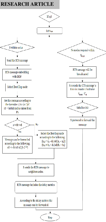
Figure 1 Proposed System Flow chart
If the particular node satisfies the Gabriel Graph then the data can be sending through the particular intermediate node. Otherwise the data can be sending through another intermediate node. So the data can be forwarded in any way in the proposed system. So congestion can be very less. Time delay can be low. Energy will be more efficient than existing system. Figure 1 illustrates the working methodology of proposed system.
Figure 2 Algorithm of Proposed System
3.1. Proposed System Functional Modules and Working Methodology
In this part, the proposed system module’s techniques are explained one by one. The proposed system explained, how the data can be forward through the best hop node that is response time is less than tmax time. The next module
explained if response time is greater than tmax means how the
data can be forward without energy loss time delay. By using
If source s and destination d are available then Set the tmax time to the RTS message
Proc:
s within the specific radius
Send the RTS message to the intermediate nodes RTS message embedding with the DDF function Select the best hop node by using DDF function
DDF function:
Set the coronas according to the formulae (√x-√x-1) r1 r1: Initial radius taken from the best hop node Pu.
If s<=R<=d then R: transmission range then
Message can be forwarded according to the following formulae
|sd| <= k√z1/z2(1-21-k)
Else
Select the best hop node according to the following formulae
{as0 = as –d0/|sd|(as – ad) }
{bs0 = bs – d0/|sd|(bs – bd)}
Endif
End function
Source s sends the RTS message to neighbor nodes.
According to the delay metrics of RTS the message can be forwarded.
End Proc
Proc a1:
If no nodes respond within tmax then
RTS message can be broadcasted
An intermediate node sends the CTS message to the source node
S sets the CTS messages’ time in counter clock wise according to the following formulae
tmax+Cn
If the particular CTS message satisfies the Gabriel Graph Algorithm Then
S protested to forward the message End Proc a1
RESEARCH ARTICLE
the proposed system the data can be forwarded with less congestion, time delay and energy.
3.1.1. First Module
Figure 3 First Module
In the first module of the proposed system work is done when the response time is less than tmax time. Three operations are
done. They are, first select the best hop node in the inner corona. If any nodes are in the center of the corona then that is the best node for forwarding the data.The selected methodology of best node is according to the equation 5. If source s satisfies this condition s<=R<=d then best hop node select by using the following formulae,
(5) If source is not satisfied the above condition then the best hop node selected according to the following formulae,
{as0 = as –d0/|sd|(as – ad)}
{bs0 =bs– d0/|sd|(bs – bd)}
If any node is ready to forward the data then that will send the CTS message to the source node also inform to other nodes that will ready to forward the data. So other nodes will not send the CTS message. Then the source node forwards the packet to destination node through the particular hop node. The data flows through that particular node. If no nodes are there in the coronas then the data can be forward as per next module steps.
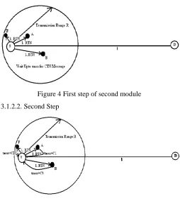
3.1.2. Second Module 3.1.2.1. First Step
This is the first step of the second module of the proposed system. This work is done when the response time is greater than the tmax time. In this, first source node sends the RTS
message to the intermediate nodes. Then source node waits for specific tmax time for sending the CTS message.But all
transmissions are in the specific transmission range only, because if intermediate nodes are in the transmission range only the source node sends the RTS message otherwise source
node cannot send the RTS message. So some intermediate nodes are must be in the specific transmission range.
Figure 4 First step of second module 3.1.2.2. Second Step
Figure 5 Second step of second module
The second step is, after the specific tmax time all intermediate
nodes are sending the CTS messages one by one. So the source node stores all CTS messages in counter clockwise. All CTS message are stored in the source node according to the equation 6,
timer = tmax+Cn (6)
In the equation 6, tmax means the maximum time that is set by
the source node to the RTS message. Then Cnmeans the
sending time of CTS message. So the source node stores all CTS messages with the sending time.
3.1.2.3. Third Step
RESEARCH ARTICLE
Figure 6 Third step of second module 4. RESULTS AND DISCUSSIONS
The proposed modelling was proved according to the following three types of metrics.
1. Transmission Time. 2. Time Delay.
3. Energy Consumption.
The proposed approach has proved these metrics through the graphs and compared both oblivious and energy efficient routing. So the proofs of above metrics are given below. The proposed system explained and compared in graphs. In the graph, the values were taken from the trace file, they are in milliseconds. So they are compared in very accurate manner. According to the metrics, the proposed system is very efficient and time delay can be reduced according to the values. The following graphs have explained the differences between oblivious and energy efficient routing.
4.1. Transmission Time
Transmission time is the routing time. That means, Transmission time is the time it takes the message to reach its destination from is source. In the proposed system, that transmission time more efficient than the oblivious routing.
No of unused Hop (N) Transmission Time
(Millisecs)
0.00 0.25 0.50 0.75 1.00 1.25 1.50 1.75 2.00 2.25 2.50 2.75 3.00
0.90737181 1.12076447775 1.39415714525 1.63754981275 1.880942481 2.236390041 2.591837601 2.947285161 3.302732721 3.57963067705 3.8565286331 4.13342658915 4.4103245452 Table 1 Transmission Time for oblivious routing
Table 1 illustrates the transmission time for oblivious routing. In this, transmission time for given by unused hop nodes is considered. Table 2 represents the energy efficient routing system’s transmission time for unused hop nodes.
No of unused Hop (N)
Transmission Time (Millisecs)
0.00 0.25 0.50 0.75 1.00 1.25 1.50 1.75 2 .00 2.25 2.50 2.75 3.00
1.233342545 1.37236311125 1.5113836775 1.65040424375 1.78942481 1.9389327875 2.088440765 2.2379487425 2.38745672 2.53640392025 2.6853511205 2.83429832075 2.983245521 Table 2 Transmission Time for EER routing
So the graph can be constructed according to the above values.
Graph 1 Transmission Time
From the graph 1, we know the EER transmission time is lower than the oblivious routing algorithm.
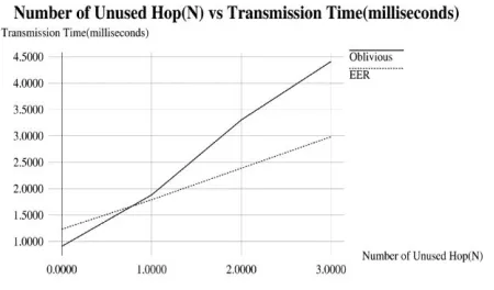
4.2. Time Delay
RESEARCH ARTICLE
No of unused Hop (N)
Time Delay (Millisecs)
0.00 0.25 0.50 0.75 1.00 1.25 1.50 1.75 2.00 2.25 2.50 2.75 0.00737181 0.45788506 0.90839831 1.35891156 1.80942481 2.36390041 2.91837601 3.47285161 4.02732721 4.7963067705 5.565286331 6.3342658915 Table 3 Time delay for oblivious routing
In the Table 3, the time delay in milliseconds for unused hop nodes is illustrated. At the time of plotting these values in the graph this will take more time for routing. So energy aware routing, that is the proposed system is very efficient one.In the Table 4, we illustrate the values of time delay for unused hop nodes for the energy aware routing scheme.
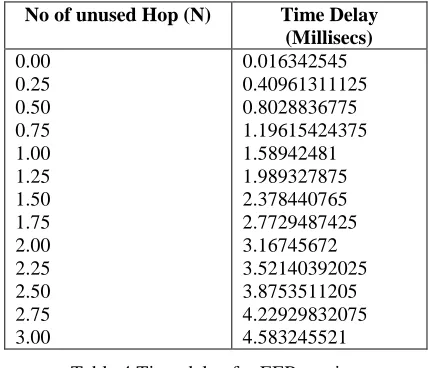
No of unused Hop (N) Time Delay
(Millisecs) 0.00 0.25 0.50 0.75 1.00 1.25 1.50 1.75 2.00 2.25 2.50 2.75 3.00 0.016342545 0.40961311125 0.8028836775 1.19615424375 1.58942481 1.989327875 2.378440765 2.7729487425 3.16745672 3.52140392025 3.8753511205 4.22929832075 4.583245521 Table 4 Time delay for EER routing So the graph will construct according to the above values,
Graph 2 Time Delay
From the graph 2, we know the EER time delay is lower than the oblivious routing algorithm.
4.3. Energy Consumption
Energy Consumption means, how the energy can be saved at the time routing. That can be monitored and compared energy efficient routing scheme with the oblivious routing. At the time of comparing, the proposed system will give the best result. In that energy can be more efficient when we compared to oblivious routing scheme. So the values in Jules for comparing oblivious and energy efficient routing. From that the proposed system proved the energy efficient routing is the best scheme for routing.
No of unused Hop (N) Energy Consumption
for Source (Jules)
0.00 0.25 0.50 0.75 1.00 1.25 1.50 1.75 2.00 2.25 2.50 2.75 3.00 0.8 1.1 1.4 1.7 2.0 2.4 2.8 3.2 3.6 3.95 4.3 4.65 5.0
Table 5 Energy Consumption for oblivious routing The table 6 illustrates the values of energy consumption for unused hop nodes for the energy aware routing scheme.
No of unused Hop (N) Energy Consumption for
source (Jules) 0.00 0.25 0.50 0.75 1.00 1.25 1.50 1.75 2.00 2.25 2.50 2.75 3.00 1.4 1.45 1.5 1.55 1.6 1.65 1.7 1.75 1.8 1.85 1.9 1.95 2.0
RESEARCH ARTICLE
Graph 3 Energy Consumption
From the graph 3, we know the EER energy consumption is lower than the oblivious routing algorithm; so the energy can be saved for each node.
4.2. Simulation Results
4.2.1. Oblivious Normal Routing
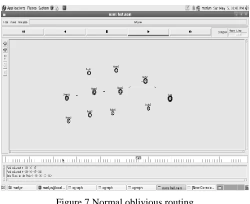
Figure 7 Normal oblivious routing
In the Figure 7, data forwarding from source to destination at the time of normal forwarding that means no problem will occur while data forwarding.
4.2.2. Oblivious Routing at the Time of Problem Occurred In the Figure 8, data forwarding at the time of problem that means congestion occurs within the source to destination packets. So Source node waits for some time and then sends the message to destination. So time can be delayed.
Figure 8 Oblivious routing at the time of problem 4.2.3. Normal Energy Efficient Routing
Figure 9 Normal EER
In the Figure 9, data forwarding from source to destination at the time of normal forwarding that means no problem will occur while data forwarding.
4.2.4. Protested Routing Of EER
RESEARCH ARTICLE
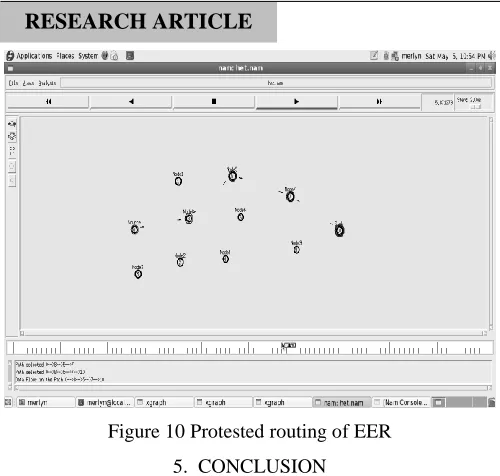
Figure 10 Protested routing of EER 5. CONCLUSION
In the EER algorithm energy will be more efficient than the existing system. In EER, if one node has less energy for forwarding the node means the source node automatically select next node for forwarding the packet. So the energy can be more efficient. Then the time delay problem also solved by Energy Efficient Routing. In the EER system, if any problem occurs while data forwarding then the source node will not stop forward the packet just protest to send in any way. So there is no data loss in the proposed system. Then the main thing is, in the EER system, RTS and CTS message can be used for forwarding the packet. For this reason, the packet sending time can be very less. By using this mechanism, the timing can be very low because if any sleeping node is there as an intermediate node then that node cannot reply, that means that node do not send CTS message to the source node. So time can be very efficient for forwarding the packet because the source node need not wait for the reply from the sleeping intermediate node. The eligible node only sends the reply as a CTS message. The last problem solved by EER system is Congestion. In the proposed work, that will be solved by using the timing mechanism. According to that, the packet can be forward through the intermediate node. When comparing the oblivious routing scheme with energy efficient scheme the EER system is the best and efficient one.
REFERENCES
[1] Jamal N. Al.Karaki, Ahamed E. Kamal, "Routing Techniques in Wireless Sensor Networks: A Survey" IEEE Wireless Communications, December 2004.
[2] Tayseer AL-Khdour, UthmanBaroudi, "Literature Review of MAC, Routing and Cross Layer Design Protocols for WSN", Wireless Sensor Network, ISBN: 978-953-307-325-5, June 2011.
[3] Shio Kumar Singh, M.P.Singh, and D.K.Singh, "Routing Protocols in Wireless Sensor Networks-A Survey",International Journal of Computer Science & Engineering Survey(IJCSES) Vol.1,No.2, November 2010.
[4] ElhamHajian and Kamal Jamshidi and Ali Boholooli, "Improve Energy Efficiency Routing In WSN By Using Automata", International Journal of Ad-hoc, Sensor & Ubiquitous Computing(IJASUC) Vol.1, No.2, June 2010.
[5] Faith Celik,AhmetZengin and SinanTuncel, "A Survey on swarm intelligence based routing protocols in wireless sensor networks", International Journal of the Physical Sciences Vol.5(14), pp.2118-2126,4 Nov,2010.
[6] AratiManjeshwar and Dharma P. Agarwal, "TEEN: A Routing for Enhanced Efficiency in Wireless Sensor Networks",IEEE Explore,pp.2009,2015, 2001.
[7] Hannes Frey, Stefan Ruhrup, and Stojmenovic, "Routing in Wireless Sensor Networks", Wireless Sensor Network, Computer communications and Networks, DOI: 10.1007/978-1-84882-218-4_4, 2009.
[8] Zhang Jin,YuJian-Ping,Zhou Si-Wang,LinYa-Ping and Li Guang, "A Survey on Position-Based Routing Algorithms in WirelessRouting",IJCCT Vol.1 Issue 2,3,4;2010 for International Conference [ACCTA-2010],3-5 August 2010.
[9] SinchanRoychowdhury,ChiranjibPatra, "Geographic Adaptive Fidelity and Geographic Energy Aware Routing in Ad HocSensor Networks",www.mdpi.org/algorithms,ISSN 1999-4893,2,158-182, 2009.
[10] Costas Busch and Malik Magdon-Ismail and Jing Xi, "Oblivious Routing for Sensor Network Topologies",SprinjerAricle, Chapter 13, Pages 381-406,2011.
Authors
Mrs.A.Anuba Merlyn received M.C.A. degree from Anna University, Tamil Nadu, India, in 2012 and received M.Phil in Computer Science from Vels University, Tamil Nadu, India. Her research interests covers cloud computing and networking.