* To whom all correspondence should be addressed.
The Basics of Controlling a Free Piston Stirling Engine
Lev Y. Lezhnev1, Denis Alekseevich Ivanov1 and Dmitriy V. Zaletov2
1Federal State Educational Institution of Higher Professional Education “Moscow state University
of Mechanical Engineering (MAMI)”, Russian Federation, 107023, Moscow, st. Bolshaya Semenovskaya, 38.
2Mobil GazService Ltd, 603000, Russian Federation, Nizhny Novgorod Region,
Nizhny Novgorod, Holodny side str. 10a. doi: http://dx.doi.org/10.13005/bbra/2220
(Received: 01 May 2015; accepted: 05 August 2015)
This paper presents an algorithm to control the motion of the displacer and the working piston of a free-piston Stirling engine (FPSE). An active control method is used to correct the motion of the pistons, which allows to adjust the pressure in the gas spring (GS) of the displacer, compression space and the buffer chamber (BC) for each operating cycle. The pressure changes inside the spaces fit in a narrow range. They are aimed to compensate the working fluid (WF) flow-over between the inner spaces of FPSE due to leakages through the sealings. The proposed algorithm and means for its implementation allow to adjust the range of the displacer and working piston travel and keep the phase angle and average WF pressure in the inner spaces within a calculated range. Combination of these parameters ensures stability of the self-oscillating process in FPSE.
Key words: Free-piston Stirling engine, Working fluid, Algorithm, Displacer, Linear electric machine.
The main focus of economic development in the XXI century is the search for promising energy conversion technologies and manufacture of engines based on high-performance thermodynamic cycles, which use renewable energy resources1. Search for energy efficient solutions in the field of autonomous power plants has led to investigation of engines with an external feed of heat (EEFH) for use in low and medium scale power plants.
One of the promising directions of EEFH development is a free piston Stirling engine (FPSE), which does not have a drive mechanism serving as a transmitter of reciprocal motion of the working pistons into rotary motion at the EEFH output. FPSE is an engine with potentially longer lifetime, because it has only two moving elements (working
piston and displacer) and it is possible to use contactless gas bearings2.
The design of FPSE provides for easy integration with a linear electric machine (LEM) to build a sealed structure. Nowadays there is a large variety of LEM types for different purposes: inductor, reactive, with permanent magnets etc. However, it is the permanent magnet machines that demonstrate high specific energy parameters, e.g. for cylindrical LEMs discussed in papers3 and4.
Improvement of LEM control algorithms leads to reduced weight and dimensions of the generator, as well as lowers internal electromagnetic losses5.
Importance of the research problem
displacer is determined by the balance of the gas and inertial forces6.
There are certain difficulties associated with assumptions commonly made in the analytical study of FPSE, which requires mandatory comparison of calculated data with experimental values and refinement of the mathematical model based on empirical coefficients. Paper7 offers an analysis of FPSE stability. A comparison of the results with data gained from experimental studies of an RE-1000 engine showed, that most of the parameters contributing to the high mechanical power output of the engine cause deviations of the load parameters. It complicates control of the FPSE self-oscillations.
Thus, it is an important task to create an algorithm and a control system, which can affect cyclic parameters of the engine.
Earlier studies, which concerned tuning and development of an algorithm to control the movement of displacer working piston in an FPSE
Development of FPSE control algorithms and systems as well as actuators to be used by the control algorithm has been an object of research and development for many years.
Paper8 reviews six methods to control an FPSE, which is used to drive a heat pump:
1) Control of medium-pressure of the displacer GS; 2) Control of displacer GS damping;
3) Control with the help of the displacer generator; 4) Control of the medium WF pressure in the
engine;
5) Control of the average compression space volume;
6) Control of the compressor dead volume.
The best target efficiency of the engine was predicted for options 4 and 6, and the worst for options 2 and 3. However, when choosing a method for controlling the engine power, we have to consider several other factors, which include technical complexity, costs of hardware, delay of the system’s response to actions of the control system and peculiarities of the engine start.
Paper9 describes control electronics of a portable charger, which is based on a low power FPSE. The engine management system, which consists of an AC-DC converter, resistive load, capacitors and DC-DC converter, controls the working piston displacement ensuring balance between the generated power and external load.
Paper10, which is dedicated to dynamic analysis of FPSE, tells that the motion range of the displacer and working piston can be controlled by parameters associated with the electrical load from an electric generator. It is an interesting solution, because most FPSEs are used in power plants to drive generators directly.
Thesis11 proposes a method to control FPSE, which is based on direct adjustment of mutual positions of the displacer and the working piston. A direct control of pistons movement provides instant control of the engine. Effective management of FPSE requires independent displacement control of the displacer and the working piston in real time. The main requirement here is an ability to control instantaneous forces introduced by linear electric machines attached to the displacer and the working piston.
Paper12 considers a controller for an FPSE-based power plant, which was successfully tested at low loads in a power plant with a dual opposed FPSE.
The reviewed works reflect a high level of interest towards addressing the issues of FPSE management, including motion control of the displacer and working piston.
Importance of the research problem
Some leakage of WF between the working spaces of the engine is inevitable during its operation. WF leaks through the displacer and working piston sealings and the displacer GS lead to deviations of the mean WF pressure in the engine spaces from calculated values.
Leakage of this kind can cause deviation of the phase angle between the displacer and the working piston from the calculated values, which alters the FPSE’s self-oscillation process up to a complete stop of the engine.
Thus, to obtain a stable output performance of FPSE and create an efficient engine, it is necessary to maintain constant phase angle and oscillation amplitude of the displacer and the working piston, which is possible by adjusting the mutual position of the pistons at each cycle.
Solution
This problem requires development of a control system, designed for seamless integration into the engine. The control system should consist of an electronic control unit and actuators operating in accordance with an established algorithm.
METHOD
To ensure stable operation of FPSE in the self-oscillatory mode it is necessary to keep the displacer and the working piston within the required oscillation field. There are several possible ways to do it based on the principle of compensatory bypassing of WF when the piston goes beyond the preset limits.
Condition for FPSE oscillatory system operation
A prerequisite for the FPSE oscillatory system operation is a dynamic balance of inertial and gas forces, acting on the displacer and the working piston. The vector sum of all applied forces must be equal to the force which causes the necessary acceleration.
The movement of the displacer and the working piston of an FPSE is governed by the sum of the following forces:
• inertia of the pistons;
• elastic force exerted by the displacer PP and the working piston PP;
• resistance (damping) force, which consists of friction, hydraulic resistance of heat exchangers and electrical load;
• force of WF pressure on the pistons from the compression and expansion space.
Besides, it is necessary to maintain constant WF temperatures in the heater and the cooler in order to obtain the calculated levels of efficiency and power. The temperature values are determined analytically and are constants for each operating mode.
Basic principles of the displacer and working piston position adjustment
Gradual shift of the center position of the displacer and working piston towards the common
working space (compression space) is possible during FPSE operation. It is a characteristic feature of this type of engine13. Such shift causes a decrease of the oscillation amplitude and reduces power at a comparable frequency of oscillations.
One of the possible solutions to this problem is the use of highly rigid diaphragm springs, designed to hold the pistons in their operating positions and limit the oscillation amplitude, within the oscillating system of the displacer and the working piston. However, the use of springs has a side effect of probable occurrence of high amplitude parasitic oscillations during the springs return motion.
Further analysis of FPSE operation established the cause of the parasitic oscillations, which is the non-linear nature of the working fluid mass flow rate in the circular gaps between the cylinder and the pistons, when the flow rate is proportional to the squared pressure difference, and deviation of the high pressure wave from the sine law14.
There are several methods of adjusting the positions of the displacer and the working piston.
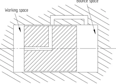
1) Controlled WF bypass, based on a controlled flow of WF between the compression space and the buffer chamber, developed by Sunpower Inc. 15, is the simplest solution for controlling the position of the working piston. Implementation of the method requires a bypass channel in the cylinder and a special hole in the central part of the piston, through which the WF rapidly flows from a compression space with a higher pressure into the buffer chamber, where the pressure is lower16. Figure 1 demonstrates the bypass method of control14.
This control system should be considered to be a single-mode system, which provides efficient control only for one single operation mode of the engine and a certain average WF pressure. 2) Another solution is a passive method of adjusting the position of the piston14. Its scheme is shown in Figure 2. This method is also based on bypassing of the WF flow when the working piston reaches a certain position.
In engines with a tight fit of the working piston and the displacer in the cylinder the pistons are used as slide valves to ensure overlap of the gas channels. In this case, the displacement of the pistons from their working positions can be prevented with a single gas control circuit. Two control circuits are necessary if the pistons are equipped with sealing rings, which complicates the system.
Thus, the second method is preferable with tight fit of the pistons, which inevitably increases the mechanical friction losses.
3) The active method of piston centering has a high accuracy and a wide range of adjustment, but it is more complex14. This method provides precise control over the compensating
WF bypass by using a bypass valve under microprocessor control. Scheme of the active regulation of the working piston position is shown in Figure 3.
The active method of control is rather complicated to be used in low-power FPSEs, but it is justified for medium and high power engines, which may require to control the piston motion when load modes change. Change of the FPSE output power may require adjustment of the center position and amplitude of the working piston oscillations as well as adjustment of the WF pressure in the buffer chamber. Microprocessor control is used to solve these problems simultaneously.
Fig. 1. Scheme of adjusting the piston position using the WF bypass method
Fig. 2. Scheme of adjusting the position of the piston using the passive method
Fig. 3. Active working piston position adjustment
In this paper we propose an active method for adjusting the position of the displacer. The piston position is corrected by LEM.
The system which controls the displacer position consists of the displacer and the working piston motion sensors, a control unit and two control valves (Figure 4).
The control system provides WF flow control between:
- displacer gas spring (GS) and compression space; - compression space and buffer chamber (BC) of the working piston.
The system is capable of constant monitoring and adjustment of the displacer position. This significantly reduces vulnerability
to changes of WF properties and WF leakage through the seals and the ignition gaps.
Controlling the engine
The purpose of the engine operation management is to regulate the motion of the displacer and the working piston, which is necessary to maintain the phase angle and stroke values of the displacer and the working piston at the required level. These parameters are supposed to be constant during steady-state operation. Tolerances for the above parameters are determined experimentally.
Implementation of the adjustment reduces the number of collisions of the displacer and the working piston with fixed elements of the engine.
Additionally, the level of WF leakage through the seals of the engine, determined by the analytical method, has an inevitable error margin, because it is hard to consider all details of internal processes.
Cyclic adjustment of the WF pressure in the working spaces is necessary during the engine operation. It is aimed to compensate for WF leakage through the inner loop seals to maintain the design parameters required to sustain the self-oscillation process.
Basic modes of engine operation
This section discusses the operating modes of FPSE, which require adjustment of a number of current parameters and the sequence of actions carried out during the adjustment. The presented algorithm involves maintenance of steady-state operation of the engine and does not consider any transitional states.
Starting and stopping the engine
The process of starting an FPSE employs its ability to autostart under influence of an external disturbing force and high WF temperature difference between the heater and the cooler.
Starting the engine requires to set the design parameters, including WF temperature in the heater and the cooler, WF pressure in the inner circuit, displacer GS and BC of the working piston. In the initial state of the system the displacer, which
is affected by a force from the GS, is at the top dead center (TDC) and the working piston is in the bottom dead center (BDC). The external disturbing force is generated by the LEM, acting as an electric motor during the engine start. Combination of the required start frequency, amplitude and power is determined by calculation and verified experimentally.
To stop the engine in order to prevent development of the residual self-oscillations and reduce the time required to stop, an algorithm is used, which creates conditions helping to reduce the amplitude of the displacer and working piston oscillations.
Maintenance of a constant phase angle
A constant phase angle value or its slight deviations within the set limits during a series of cycles is a prerequisite for a stable and constant self-oscillation process and stable output parameters of the engine.
Causes of deviations of the phase angle are:
• Delayed/advance motion of the working piston; • Delayed/advance motion of the displacer; • Combination of both factors.
The function of controlling the motion of the working piston is assigned to the LEM. Surplus electricity is discharged to an energy storage buffer through an energy converter.
Position Encoder Acquisition Block LEM Control Block Valve Conrol Block Xd, Xp, Angle Xd, Xp,
S Currents and Voltages
Acquisition Block Iu, Iw, Idc, Udc Si g n al s f ro m P o si ti on se n so rs Si g n al s f ro m c u rr en t an d v o lt ag e se n so rs IG B T C on tr o l S ig na ls Si g na ls t o v al ve s Блок управления реального времени Graphical User Interface
Data Logging Block Windows RT: 9074 FPGA: 9074 RT: 9074 Si g nal s f ro m t e m p e ra tu re an d m as s f lo w r at e s en so rs Pressure Acquisition Block Si gn al s f ro m P re ss u re Sen so rs
Realtime control block
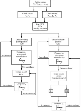
Further we describe events that occur during the engine operation and a control algorithm for each of them. A block diagram with the control algorithm is shown in Figure 5.
Working piston moves in the direction of TDC, but the displacer starts to move toward BDC with a delay. Such development of the process leads to an increase of the phase angle.
Cause: displacer GS too rigid.
Solution: let some WF pass from the displacer GS into the working piston BC through the K-1 valve. It is possible, because while the piston moves towards the TDC, the pressure in the working piston’s BC lowers and it creates enough pressure difference to initiate a free flow of a sufficient amount of WF into the working piston’s BC.
Movement of the working piston toward TDC and early start of the displacer movement toward BDC reduces the phase angle
Cause: displacer GS too soft.
Solution: let some WF flow from the compression space into the displacer GS through the K-2 valve. When the piston moves toward TDC, the pressure in the compression space increases and creates enough pressure difference to initiate a free flow of a sufficient amount of WF into the displacer GS.
Delayed start of the displacer movement from BDC reduces the phase angle
Cause: displacer GS too soft.
Solution: let some WF flow from the compression space into the displacer GS through the K-2 valve. Reducing the volume of the compression space increases the pressure inside and the pressure difference drives the adjustment volume of WF to the displacer GS.
Early start of the displacer movement from BDC leads to an increase of the phase angle
Cause: displacer GS too rigid.
Solution: let some WF pass from the displacer GS into the working piston BC through the K-1 valve. When the working piston is near the TDC, the pressure in the working piston BC drops and creates a pressure difference against the displacer GS, which is sufficient to drive the adjusting volume of WF into the working piston BC.
Operation of the K-1 and K-2 valves
After the control unit receives a signal from the displacer position sensor (PS) it compares
the received coordinates with a value corresponding to the calculated harmonic motion law. The control unit can access a data array in the form of a function of the displacer and working piston motion from the time.
If the received coordinates fail to comply with the law, a process of adjustment starts following one of the options described in p. 2.2.1 - 2.2.4.
Valves K-1 and K-2 with needle closure members, equipped with a high-speed piezoelectric actuator serve to bypass the WF. The needle closure members with a low flow coefficient ensure fine adjustment step. Length and period of the control signal are set during the adjustment process.
Piezoelectric valve actuators are fast enough to control the WF bypass. This provides the technical capability to control the displacer.
One control step is taken to be a 1 ms long valve opening. At the next working cycle the actual movement is compared with the harmonic motion law. If a mismatch is detected, the control unit selects which valve, K-1 or K-2, must be activated. A control impulse is sent to the chosen valve and another comparison with the motion law is made.
The duration of a single complete cycle at the operating frequency of 50 Hz is 20 ms. Thus, the control valve response time of 1 ms allows make the adjustment process flexible.
Ensuring constant motion of the displacer and the working piston
The design of the displacer includes buffer elements that prevent destruction of engine parts if the working stroke length is exceeded. However, long-term engagement of the buffer elements is not acceptable and the engine control algorithm incorporates measures to maintain constant stroke of the displacer and the working piston.
Two position sensors, which send data to the PS processing unit, are used to determine the positions of the displacer and the working piston. Several types of displacement sensors became widespread: inductive17, capacitive18, magnetostrictive, ultrasonic, digital optical, magnetic encoders and other19.
because the working fluid, which movement must be measured, is put in an isolated area without free access. Ultrasonic position sensors lack the necessary speed.
A displacer PS consists of two coils around the cylinder with an overall height of two piston strokes. Their principle of operation is based on inductance change when a magnetically conductive material is put inside the contours. The chamber walls are made of a non-magnetic material, but a part of the cylinder is magnetic. Inductance of the loops formed by the coils change as it moves. The change of inductance is converted into a proportional voltage in the range from -10 V to +10 V. The PS signal goes to the processing unit, where it is compared with the coordinate required by the law of displacer motion relative to the working piston. The PS data are processed and allow to calculate acceleration of the displacer.
Probability of the displacer amplitude deviation from the set limits in both possible directions is determined after analyzing the data from the displacer PS.
Then, a signal of the required length is sent to the control valve, which controls the amount of WF entering or leaving the respective space.
The algorithm used to control the displacer stroke is similar to the process discussed in pp. 2.2.1 - 2.2.4.
The position of the working piston is determined by the PS integrated into the LEM and producing a digital two-phase pulse signal with a zero position. Adjustment of the working piston movements is performed using the LEM, which operates either as a generator to brake the piston, or as a motor to accelerate the piston.
Thus, the PS signal processing unit is an ADC and a dual-channel bidirectional counter. Its output signals indicate the current positions of the displacer and the piston, full stroke (oscillation amplitude) and the phase angle between them.
Engine power control
We should also touch upon the issue of regulating the engine power, which is normally adjusted by changing the following parameters20:
• Maximum temperature of the working fluid; • Pressure of the working fluid;
• Phase angle between the displacer and the working piston.
The power control method based on changes of the WF temperature has significant drawbacks, because hot parts of the engine have great thermal inertia. This method cannot provide high reaction speed following the temperature changes.
It is not possible, to achieve quick engine power adjustment based on heater temperature changes. Besides, using heater temperature to control the engine is undesirable since this will reduce the temperature ratio in the engine, reduce its thermal efficiency and lessen the power output21. The fastest way to regulate the power of the engine is to change the WF pressure.
Power control by adjusting the displacer and working piston stroke.
FPSE power can be controlled by changing the displacer and working piston stroke. This method of adjustment better suits engines with free displacer and working piston than crank engines. Changing of external load of an FPSE can lead to a deviation of the working piston:
So, when the load from the LEM decreases, the working piston stroke increases to the maximum, and when the LEM load drops the working piston stroke decreases.
Reducing the displacer stroke facilitates reduction of the mass WF flow between the compression and expansion spaces of the engine and lowers the amplitude of pressure variation for a cycle.
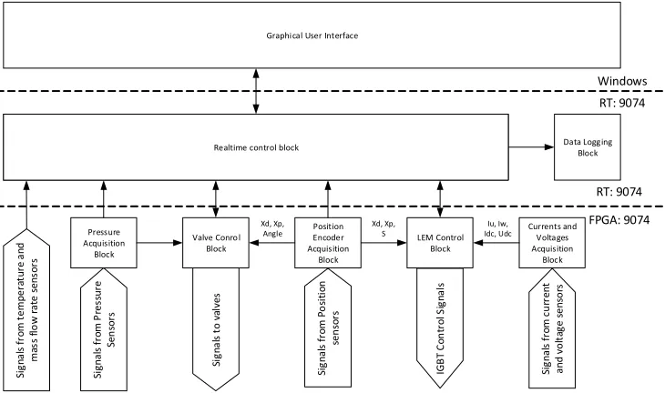
Structure of the engine control software
The software, the block diagram of which is shown in Figure 6, is designed for a real-time system based on NI CompactRIO controller and runs in LabVIEW 2014. The source programming language is a visual typed stream language G/ LabVIEW. Labview and CompactRIO are widely used for a variety of tasks requiring quick and accurate control, for example22 and23. The development of the software involved wide use of modern software development tools, as well as algorithm development modules in the form of finite automata - Statechart Module.
EHSE_FPGA.VI software module and runs in the field programmable gate array (FPGA) system module. At the same time, the code responsible for high level control and interaction with the operator’s shell belongs to the EHSE_RT.VI a software module and runs at the real-time system level on cRIO-9074 RT. The operator’s shell EHSE_Win.VI runs on a personal computer of the operator and accesses the control system through a network connection.
The valve control unit receives at its input the actual and nominal phase angles and information about the pressure in the spaces, which become the basis for making decision to open one of the valves.
The control unit is a high-level real-time control system. It serves as the main system controller and performs the following functions:
1. Running of the basic system algorithm in the form of a finite state machine that determines the engine operation mode and issues commands for the FPGA block;
2. Interaction with the operator shell;
3. Processing and transmission of data from temperature sensors;
4. Logging of the current system operation parameters into protocol file.
Operator’s shell runs on a personal computer and provides a graphical user interface, which allows to manage and configure the parameters of FPSE operation.
RESULTS
The results of this work include an overview of existing methods of adjusting the displacer and working piston position. On the basis of this analysis we propose an active method of adjusting the displacer position, based on WF bypass between the compression space, displacer GS and the working piston BC.
A control algorithm was developed to implement the active method. The algorithm provides cyclic displacer position control. implementation of this algorithm allows to maintain the required phase angle during FPSE operation. Two valves with needle closure members and piezoelectric actuators, capable of providing sufficient speed, are used for cyclic control of the WF bypass.
The software implementation of the control system is presented in a block diagram, showing interaction of different software modules. Processing the data from the sensors and the generation of control signals is done at the FPGA module level of the CompactRIO FPGA block. The main engine control algorithm is implemented at the level of the CompactRIO RT real-time module. At the same time, all interaction between the equipment and the operator is supported by a software module developed for PC.
The software that we developed fully implements the required FPSE control algorithms.
DISCUSSION
Experimental studies play important role during research and development of FPSE-based power plants. Operation of the engine involves a lot of non-stationary processes, parameters of which are hard to obtain by analytical method. Furthermore, FPSE should be regarded as a single dynamic and thermodynamic system, consisting of moving masses (displacer and working piston) and working spaces for compression and expansion, heat exchange circuit (heater, regenerator and cooler), displacer GS and working piston BC, filled with WF.
The data obtained during experimental studies allow to introduce empirical coefficients to refine the mathematical model, developed to calculate the FPSE under development.
Implementing the algorithm required to solve several technical problems. It is necessary to use displacement sensors to determine the movement of the displacer. The choice of the PS type and location causes certain difficulties, because the bottom of the displacer during engine operation is always very hot. In this work we decided to use an inductive displacer PS, capable of operating at a frequency of at least 1000 Hz. The design of the PS and applied engineering solutions must ensure reliable operation of the sensor in close proximity to the displacer bottom.
actuators will allow to adjust the pressure in the engine spaces during each operating cycle.
CONCLUSION
Information and design principles of the control algorithm, discussed in the analysis of the displacer and working piston motion control methods, were used to create the active FPSE control system.
The algorithm of the control system operation was developed on the basis of the requirements for engine management and technical specifications of the actuators used in the system. In order to implement the FPSE control algorithm we developed engine management software, which consists of several software modules.
The problem of creating the algorithm and FPSE control system, that maintain the phase angle and oscillation amplitude of the displacer and the working piston within the calculated range, is important for development of medium- and high-power FPSEs.
To implement the main stages of regulation, provided for in the developed algorithm, in the FPSE control system we used technical solutions that can offer high speed and precision of control.
The results of this work can be used in the development of hardware and software to manage a test bench for experimental studies of FPSEs.
The importance of experimental studies of the engine during its creation is obvious, because there is no universal method for calculating FPSE, that would allow to design an engine without bench tests.
ACKNOWLEDGMENTS
This paper has been written in the framework of a grant agreement from June 5, 2014 No 14.577.21.0071 (Unique ID of applied research (project) RFMEFI57714X0071) with financial support of the Ministry of education and science of the Russian Federation.
REFERENCES
1. Kirillov, N.G. Production of the Stirling engine -a new br-anch in mech-anic-al engineering of the XXI century. Turbines and diesel engines, 2010;
#2 (29): 2-5.
2. Shaltens, R.K. Solar powered Stirling cycle electrical generator. National Aeronautics and Space Administration. Lewis Research Center, Cleveland, OH, 1991; 1: 269-278.
3. Akhondi, H., Milimonfared, J. Design and Optimization of Tubular Permanent Magnet Linear Motor for Electric Power Steering System. Journal of Asian Electric Vehicles, 2009;
7: #2.
4. Ryzhkov, A.V. Analysis and choice of reasonable constructions of the cylindrical linear motor with electromagnetic excitation (Dissertation presented for the degree Doctor of Philosophy in the Faculty of Engineering). Voronezh state technical university. Voronezh 2008.
5. Bagg, S.D. Linear alternator technologies used for free piston Stirling engines. Nuclear and Emerging Technologies for Space 2012. 6. Lewandowski, E.J., Regan, T.F. Overview of
the GRC Stirling Convertor System Dynamic Model. AIAA–2004–5671: 2004.
7. B´egota S., Layes G., Lanzetta F., Nika Ph., Stability analysis of free piston Stirling engines.
The European physical journal applied physics,
2013; 61: 30901. DOI: 10.1051/epjap/ 2013120217.
8. Griffin, F. P., Domingo, N., Chen, F. C., Evaluation of power control methods for free-piston Stirling engine driven heat pumps. Oak Ridge National Laboratory, Oak Ridge, Tennessee 1987.
9. Holliday, E., Keiter, D.E. Control Electronics for Palm Power 35W Free-Piston Stirling Engine. International Energy Conversion Engineering Conference. San Francisco, California 2005. 10. Ulusoy, N. Dynamic analysis of free piston
Stirling engines (Ph.D. thesis). Case Western Reserve University, Cleveland, OH: 1994. 11. Strauss, J. M. Direct piston displacement
control of free-piston Stirling engines (Dissertation presented for the degree Doctor of Philosophy in the Faculty of Engineering). Stellenbosch University, South Africa 2013. 12. Gerber, S. S. Advanced Controller Developed
13. Walker, G. Stirling engines. Clarendon Press. Oxford; 1980.
14. Walker, G., Senft, J.R. Free Piston Stirling Engines (Lecture Notes in Engineering), Springer-Verlag Berlin, Heidelberg, 1985; DOl: 10.1007/978-3-642-82526-2.
15. Wood, G. Lecture Notes for Stirling Engine Workshop. Sunpower Inc., 6 Byard St., Athens, Ohio 45701, 1980.
16. Van der Woude, R.R., Zutt , J.G.M., Vriesema, B., Beckers, G.J.J. Limitations of piston centre shift in free piston Stirling engines. Published in the Conference Proceedings of the International Stirling Forum, Osnabriick 2006.
17. Sysoeva, S. Automotive position sensors. Modern technology and prospects. Part 9. The classic inductive transducers - a reliable supply. Components & Technologies, 2005; #9.
18. Sysoeva, S. Automotive position sensors. Modern technology and prospects. Part 11. Capacitive sensors - new devices at the
automotive market. Components & Technologies,
2006; #4.
19. Sysoeva, S. Automotive position sensors. Modern technology and prospects. Part 13. The final comparative analysis. Conclusions and updates. Components & Technologies, 2006; #7. 20. Reader, G.T., Hooper, L.C. Stirling engines. Trans. from eng. Mir Publishers. Moscow 1986. 21. Danilichev, V.N., Efimov, S.I., Zvonov, V.A., Kruglov, M.G., Shuvalov, A.G. Stirling engines. Edited by Kruglov, M.G. Mashinostroenie Publishers. Moscow 1977.
22. Tian, Y., Jiang, L., Ming, L., Bin, H. LabVIEW and CRIO Linear Control of a Coaxial Two-wheeled Mobile Robot. Third International Conference on Measuring Technology and Mechatronics Automation (ICMTMA). Shangshai; 2011. 23. Zia, M., Curley, A., Duran, O., è Razmkhah, O.