Themed Section : Engineering and Technology
Optimization of Wireless Power Transfer System for
Implantable Biomedical Devices Using Firefly Method
1Karan Kamboj, 2Neha Gupta
1M.Tech Scholar, 2Assistant Professor, Department of EE, OITM, Hisar, India
ABSTRACT
The paper presents analysis of the transferred power of an inductive link circuit with different network configurations of capacitors connected to primary and secondary coils. The performance for both objective functions is observed using four capacitor, two capacitors connected to the input coil and two capacitors connected to the output coil. However, the output in this circuit configuration for both efficiency and output power are very complex and a numerical method is applied to calculate the capacitors values. Since an in-depth search would be long therefore, some simplifications is assumed to reduce the search space and the time. Therefore, an algorithm based on a optimizer method is developed and successfully applied. The results for both efficiency and output power of four capacitors configuration are compared with other approaches, such as the single and two capacitors compensation. Finally, a basic prototype is built and the theoretical results are validated. Both simulated and experimental results of the four capacitor configuration showed a significant improvement on the efficiency and output power of the inductive link.
Keywords : Electromagnetic Coupling, Optimization.
I.
INTRODUCTIONElectronic devices have seen substantial lowering in energy consumption with the integrated circuit technology advances. Hence, the batteries did not become less important or dispensable, but they turned into one of the heaviest components in modern portable electronic devices [1]. For instance, in implantable devices, the small size of batteries is essential. In such systems, the battery has a direct effect on the user‟s life and some malfunction is a serious threat to the patient‟s health [2]. In addition, as an alternative to batteries, the use of a power cord becomes a problem due to reliability and maintenance [3]. One possible replacement to batteries or power cords is powering through magnetically coupled coils. This alternative was already broadly employed in many different applications, where a contactless
power system is a necessity, such as biomedical devices [2], [4], [5] and instrumentation systems [6], among others [7]–[9]. The magnetically coupled system is usually represented by two inductances, L1
(primary side) and L2 (secondary side), and a low
compensated with more than two capacitors.[8], [13], and [14] presented four circuit topologies to power transfer through inductive coupling that make use of only two capacitors. The topologies are: compensation by a capacitor in series with the primary and secondary coils (SS), a capacitor in series with the primary and another capacitor in parallel with the secondary coil (SP), a capacitor in parallel with the primary and another capacitor in parallel with the secondary coil (PP), and a capacitor in parallel to primary coil with another capacitor in series with the secondary coil (PS). The term compensation is about the utilization of a capacitor in series or parallel with the respective coil to reach resonance, or the cancelation of the inductive reactance.
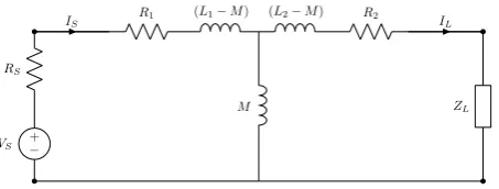
Fig. 1. Transformer model equivalent circuit
This paper analysis of an inductive link connected to two capacitor on both input as well as output coils [15].
The flow of paper is as section I discusses about the introduction with survey. Section II develops and presents the system of equations necessary to implement the full four capacitor circuit‟s compensations for both objective functions: output power and efficiency. The results are presented and compared with other useful configurations in Section III. Then, the conclusion, discussion, and future works are exposed in Section IV.
II.
METHODOLOGYThe basic wireless power transfer system composed by two coils, L1(primary) and L2(secondary), the
equivalent losses in the coil, R1(primary) and
R2(secondary), and mutual inductance M = k√L1L2 can
be represented by an equivalent T circuit of a transformer model (Fig. 1), where VS is a sinusoidal
source with an internal resistance RS and ZL is the
load.One should notice the behavior of the circuit from Fig. 1 when the coupling coefficient k is very small. In these cases, analyzing the primary side only, the inductance M can be simplified to a short circuit because jωM jωL1and jωM jωL2. Therefore, the
primary is not influenced bythe secondary load.
Considering a steady state RS = 0 and the load ZL = RL
(For analysis simplifications), the total efficiency (β) of the circuit of Fig. 1 and the output power on RL are
given by
(1)
Where
(2)
It is clear, from (1), that the only way to improve the total efficiency (β) of the basic wireless transfer system shown in Fig. 1 without a circuit modification is to increase the frequency ω. When k, L1, L2, R1, R2,
and RL are constants, the maximum theoretical
efficiency will be reached when ω →∞ (3). However, the power on the load goes to zero in this situation and the resulting circuit is useless, as can be observed with (2).
(3)
Fig. 2. Transformer model equivalent circuit
A very basic and intuitive analysis is supposing the circuit of Fig. 1 composed by ideal inductors (without loss resistancesR1 and R2) and with a resistive load. In
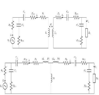
this particular case, four ideal capacitors would cancel all the inductances (Fig. 2). This would lead the load directly connected to the input voltage source by way of the resonance.
At resonance, the capacitance c2cancels the inductance (L1–M), c3 cancels the inductance (L2–M),
and c1and c4cancel the inductance M.
However, when lossy resistors are added to the voltage source (RS), capacitors (RC1 to RC4), and
inductors (R1 and R2), the analytical equations for the
objective functions (efficiency or output power) become very complicated. In this case, the optimization model is highly nonlinear and has more than one local minimum, as shown in Fig. 3, which represents the output power as a function of only two capacitors with the remaining variables held constant. The inclusion of additional variables and simultaneously accounting for the discrete nature the capacitor values makes the optimization model more complex and non-convex. Therefore, the use of classical methods of optimization becomes unattractive and a numerical method is suitable to find the capacitors values that improve power output and efficiency of the inductive link. The simplest method would be an exhaustive search [17] , but computationally very costly. Thus, we adopted a simple approach based on a firefly method. Taking samples from the search space would lead to the optimal point if there are an infinite number of trials [18]. With a finite number of trials, one can get as near as necessary to the optimal point, depending only on the computational power available.
Although there may be many solutions to the optimization problem, its practical implementation can only be performed to a limited set of capacitors. This set of capacitors (disregarding associations) is composed by commercial values of capacitances. Indeed, this is a constraint of the optimization problem. Thus, the search space of possible values of capacitance was limited to 216 commercial components (based on the IEC 60063 E24 series [19] multiplied by 10−12 up to 10−4), which give a total of
2176782336 possibilities. The basic idea is to pick up four capacitors from the 216 possible values (a discrete and uniform distribution) and calculate the objective function (output power on the load and efficiency). This procedure is repeated a reasonable number of times (107 trials in this paper or 0.46% of
the total search space). Since the problem is defined by NcC (where Nc is the total number of different
capacitances and C is the number of capacitors used in the circuit), it is clear that the circuit compensated by two capacitors can be calculated with all the possible values (46656) with a low computational cost.
As a simplification to the problem, all series lossy resistances are considered equal RC = 0.1 (based on the
experimental setup).
The basic algorithm employed to find the best set of four capacitors is as follows:
1) initialize best β = 0 and best Po= 0;
2) store n constants in a vector (in this paper represents 216 different values of capacitances);
3) Select a number from one to n (n = 216) using firefly optimization technique. These numbers are used as indexes of the array of capacitances. This procedure is repeated to generate the values for C1, C2, C3, and C4;
4) calculate β and Pout;
5) Test if β and Pout are better than best βand best
Pout, respectively. If one test is true, store the
6) Go to step 3 until the limit number of iterations is reached.
Fig. 3. Prototype variable coupling measurements.
In addition, the method proposed in this paper provides a simple way to accomplish a multiobjective search (efficiency and output power) and find the Pareto frontier from the calculated points with a very little increase on computational costs.
In the following section, the results of the circuit with four capacitors compensation are presented and compared with other useful circuit configurations for efficiency (β) and output power (Pout).
III.
RESULTSThis section presents the results of computed values Fig. 4. Inductive link circuit and the equivalent T model with four capacitors configuration.
Simulations are carried out based on the circuit parameters from the prototyped inductive link shown in Fig. 4. As described in the previous section, the solutions are discrete, arranged to a set of arrount 216 possible values of capacitances. The parameters of the experimental circuit are: RS = 0.1 , R1 = 1.8 , R2 = 2.28 ,
L1 = 218.4 μH, and L2 = 311.4 μH. All capacitors, even
if not mentioned in the text, are assumed to have a series lossy resistance RC = 0.1 . The voltage source VS
is sinusoidal with Vpeak = 5 V and f = 50 kHz. Again,
the load was simplified with ZL = RL. The main
objective of this section is to present a comparison of the efficiency and output power (power on the load) of the circuit from Fig. 1 with Randomization and Firefly Algorithm against the results of the configurations with only one compensation capacitor: series with the input (1Cap-SI), parallel with the input (1Cap-PI), series with the output (1Cap-SO), and parallel with the output (1Cap-PO); with two compensation capacitors (2Cap-SS, 2Cap-SP, 2Cap-PS, and 2Cap-PP); and the ideal circuit compensated by four ideal capacitors and the full four capacitor compensation considering all lossy resistances. To reduce the amount of data, the circuits output are evaluated with only five resistive loads values RL (6.8,
47, 270, 470, and1k) and only four coupling coefficient k (0.004, 0.04, 0.46, and 0.88). These first two values of k represent weak coupling such as two loosely coupled coils. One should notice that both solutions of circuits compensated by one and two capacitors were computed with exhaustive search. The compensation capacitors of the ideal circuit were calculated with and approximated with the E24 series. Finally, the solutions of the full compensated circuit considering all.
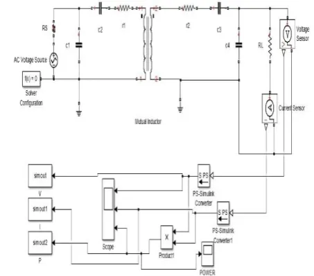
Fig. 5. Simulink model of 4 capacitor system.
Where VIN (VP) and VOUT (VP), phase between VIN and
VOUT, φ (rad) were monitored to compute the output
power on the load and the efficiency of the inductive link. These parameters were also used to generate the simulation results. Table 1 shows both measured and simulated results for output power & efficiency of the inductive link with randomized algorithm
Results are computed using the randomized method. Fig.6 shows the flow chart of randomized algorithm which describe the step by step computation of output power and efficiency by selected randomly a no. from 1 to n and generate the value for capacitor C1,C2,C3 and C4 . After that it will test the efficiency and output is better or not. If yes then capacitor values are stored if not then again give a call for random selection of capacitor value. The flow chart of randomized method is given Ahead.
Fig.6 Flow chart of Randomized Method
Start
Parameter initializations (Rs,Vs,..)
And Initialize best-
𝛈
=0 and best-Pout=0
Store n constants in a vector
Randomly select a no from 1 to n and
generate the values for C1, C2, C3, C4
Calculate
𝛈
and Pout
test if
η
and
P
out are better than best
η
and best
P
out, Respectively.
Store the capacitors values and update
that best value variable. Also update the
max Power and max. Efficiency
Fig.7 Output power with 4 capacitor using Randomized Method
Fig.8 Efficiency with 4 capacitor using Randomized Method
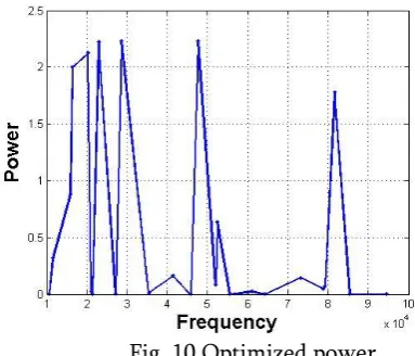
Results are computed using Randomized method using algorithm at different values of capacitor using random values from 1 to n. Now we will compute using Firefly algorithm with four capacitor simulink model used same in Randomized method with different technique. In this method the behavior of fireflies is used. All possible capacitor combination formation is taken as firefly then call firefly optimization function to find optimized parameters and compute the efficiency and power with each combination. Flow chart for optimization is drawn ahead in fig 9. And the results of power and efficiency is computed in fig10 and fig.11 respectively.
Fig. 9: Flow chart of firefly method for optimization
Fig. 10 Optimized power
Start
Parameter initializations (Rs,Vs,..)
Capacitor table formation
All possible capacitor combination
formation as fireflies
Call firefly optimization
function to find
optimized parameter
Update solution set accordingly to max.
power selection condition and again
calculate the max. power and max.
efficiency for different parameters
Check the results and plot the graph for
max. efficiency v/s frequency
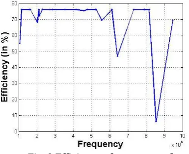
Fig. 9 Efficiency of power transferred
By comparing the measured and simulated results presented in figures, one can observe that most of the cases match. This circuit was also simulated by SPICE presenting practically the same results. The small differences in results can be assigned to measurement errors of parameters or variables, as well as possible non-idealities of the ac source. Thus, we believe that the experimental values found in this paper serve to validate the presented theoretical
IV.
CONCLUSIONThis paper presents different configurations of circuit‟s compensations as means of improving the efficiency and the energy available to the load in power transmission systems that use inductively coupled coils by using firefly algorithm. The performance of these configurations was compared with a proposed and implemented four-capacitor compensation method.
Initially, we made a theoretical analysis of the efficiency and power delivered to a load by the inductive link featuring four capacitors and it became clear that in both cases, the analytical equations are very complicated. Furthermore, the values of the discrete components are natural constraints of experimental circuits, generating a discrete space of solutions. Thus, the capacitors values were computed using a search method based on a limited number of trials. The results of this paper represent the optimal values for both (not simultaneous) objective functions in 107 trials. The efficiency and output power from
this circuit were computed with the application of the capacitor‟s values found by the algorithm in each trial. Thus, the best results for each load resistor with a set
of capacitors were chosen and compared with the results of the inductive link compensated with other usual approaches, such as one and two capacitors connected on the input or output.
Table 1 Analysis based on results calculated from
different techniques PARAM ETER VAL UE VOLT AGE PO WER EFFICI ENCY FREQU ENCY INC R.
DEC. DEC. INCR.
FREQU ENCY DEC . INCR. INC R. DEC. LOAD RESIST ANCE INC R.
INCR. DEC. DEC.
LOAD RESIST ANCE
DEC DEC INC R INCR COUPLI NG FACTO R INC R.
INCR. INC R INCR COUPLI NG FACTO R DEC .
DEC. DEC. DEC.
The compensation method presented in this paper was the only one to have a good performance, for both efficiency and output power, for all combinations of load RL and tested coupling
In addition, the inductive link compensated with four capacitors using firefly algorithm obtained a significative improvement of efficiency when compared with the results of the same inductive link with four capacitors using randomized algorithm. In addition, the secondary efficiency of the inductive link, a serious issue considering implantable devices, hits 75% with a coupling coefficient of only 0.004 in one specific case simulated with SPICE using the four-capacitor compensation.
The capacitor values determined by the described fireflymethod were compared with other usual optimization methods. The most of values are very close to the values obtained by classical optimization methods (reduced gradient). Such methods are especially sensitive to initialization on nonconvex problems. We also observed that the results have different sensibilities with the capacitors. For instance, the power on the load has weak dependence on C1
and efficiency has weak dependence on C1 and C2.
The power on the load and the efficiency of the circuit was also simulated by SPICE presenting practically the same results. Finally, the simulated results were confronted and validated with measurements made with an inductive link prototype and most of the results match.
V.
REFERENCES[1] Anil Kumar RamRakhyani, ShahriarMirabbasi, and Mu Chiao,„‟Design and Optimization of Resonance-Based Efficient Wireless Power Delivery Systems for Biomedical Implants‟‟ in IEEE Transactions On Biomedical Circuits And Systems, Vol. 5, No. 1, February 2011
[2] Hussnain Ali, Talha J Ahmad, and Shoab A Khan,”Mathematical Modeling of an Inductive Link for Optimizing Efficiency,” 2009 IEEE Symposium on Industrial Electronics and Applications (ISIEA 2009), October 4-6, 2009, Kuala Lumpur, Malaysia, October 4-6, 2009. [3] Hussnain Ali, Talha J Ahmad, and Shoab A
Khan,” Inductive Link Design for Medical Implants,” 2009 IEEE Symposium on Industrial Electronics and Applications (ISIEA 2009), October 4-6, 2009, Kuala Lumpur, Malaysia, October 4-6, 2009.
[4] TakehiroImuraand Yoichi Hori, “Maximizing Air Gap and Efficiency of Magnetic Resonant
Coupling for Wireless Power Transfer Using Equivalent Circuit and Neumann Formula,”IEEE Transactions on Industrial Electronics , February 2011.
[5] Wenshan Hu,Qijun Deng and XingranGao, “Optimization Algorithm and Practical Implementation for 2-coil Wireless Power Transfer Systems,”2014 American Control Conference (ACC)June 4-6, 2014. Portland, Oregon, USA.
[6] Ho Yan Leung,Aiguo Patrick Hu, “Design methodology for Inductive Power Transfer systems targeting high power Implantable Devices,” Crown978-1-4673-5762-3/13, 2013. [7] KanberMithatSilay, Catherine Dehollain, and
Michel Declercq,”Inductive Power Link for a Wireless Cortical Implant with Biocompatible Packaging,” IEEE SENSORS Conference, 2010. [8] Alexey Denisov and Eric Yeatman,”Ultrasonic vs.
Inductive Power Delivery for Miniature Biomedical Implants,”IEEE International Conference on Body Sensor Networks, 2010. [9] Juseop Lee, Yong-Seok Lim, Woo-Jin Yang, and
Seung-Ok Lim, ”Wireless Power Transfer System Adaptive to Change in Coil Separation,”IEEE Transactions On Antennas And Propagation, Vol. 62, No. 2, February 2014.
[10] Y.-H. Chao, J.-J. Shieh, C.-T. Pan, W.-C. Shen, and M.-P. Chen, “A primary-side control strategy for series-parallel loosely coupled inductive power transfer systems,” in Proc. 2nd IEEE ICIEA, May 2007, pp. 2322–2327.
[11] M. Kiani and M. Ghovanloo, “The circuit theory behind coupled-mode magnetic resonance-based wireless power transmission,” IEEE Trans. Circuits Syst., vol. 59, no. 8, pp. 2065–2074, Aug. 2012.
[12] R. Azambuja, V. J. Brusamarello, S. Haffner, and R. W. Porto, “Full four capacitor circuit compensation for inductive power transfer,” in Proc. IEEE Int. Instrum. Meas. Technol. Conf., May 2013 , pp. 183–187.
[13] V. J. Brusamarello, Y. B. Blauth, R. Azambuja, I. Muller, and F. R. de Sousa, “Power transfer with an inductive link and wireless tuning,” IEEE Trans. Instrum. Meas., vol. 62, no. 5, pp. 924– 931 , May 2013.
[14] H. A. Taha, Operations Research: An
[15] J. S. Bendat and A. G. Piersol, Random Data: Analysis and Measurement Procedures, 4th ed. New York, NY, USA: Wiley, 2010.
[16] J. O. Mur-Miranda, G. Fanti, Y. Feng, K. Omanakuttan, R. Ongie, A. Setjoadi, et al., “Wireless power transfer using weakly coupled magnetostatic resonators,” in Proc. IEEE ECCE, Sep. 2010 , pp. 4179–4186.
[17] R. Harrison, “Designing efficient inductive power links for implantable devices,” in Proc. IEEE ISCAS, Jun. 2007, pp. 2080–2083.