© 2016 IJSRSET | Volume 2 | Issue 1 | Print ISSN : 2395-1990 | Online ISSN : 2394-4099 Themed Section: Engineering and Technology
Compare and Contrast the Packet Loss between Different Nodes
within Same Link at Particular Interval of Time and at Specific Time
Dr. Rajdev Tiwari, Parul Sirohi
Department of Computer Science and Engineering, Noida Institute of Engineering and Technology. Uttar Pradesh, India
ABSTRACT
Measurement and estimation of packet loss characteristics are challenging due to the relatively rare occurrence and typically short duration of packet loss episodes. While active probe tools are commonly used to measure packet loss on end-to end paths, there has been little analysis of the accuracy of these tools or their impact on the network. The objective of our study is to understand how to measure packet loss episodes accurately within same link within particular interval of time. We begin by testing the capability of standard end-to-end measurements of loss in a controlled laboratory environment using network simulator 2.35. Our tests show that loss characteristics reported from different nodes within same link at different interval of time can be quite accurate over different nodes within same link at specific interval of time. Motivated by these observations, we introduce a new algorithm for packet loss measurement that is designed to overcome the deficiencies in standard tools.
Keywords: TCP Congestion Window, Front End Server, Congestion Control, Droptail Mechanism, Source Code.
I.
INTRODUCTION
TCP Congestion Control
TCP uses a round-trip delay estimate for its adaptive windowing scheme to transmit data reliably over an unreliable network with time varying bandwidth. Similarly a smoothed variance (estimated as mean difference to avoid square root calculations in the kernel) is also maintained (Tahoe TCP). If an acknowledgement for a segment is not received within the timeout, it is re-transmitted. TCP uses a congestion window in the sender side to do congestion avoidance. The congestion window indicates the maximum amount of data that can be sent out on a connection without being acknowledged. TCP detects congestion when it fails to receive an acknowledgement for a packet within the estimated timeout. In such a situation, it decreases the congestion window to one maximum segment size (MSS), and under other cases it increases the congestion window by one MSS. There also exists a congestion window threshold, which is set to half the congestion window size at the time when a re-transmit was required.
The inherent assumption in this mechanism is that lack of an acknowledgement is due to network congestion. If a packet, however, is lost by the network for reasons other than network congestion, then waiting for the timer to run out is wasteful. This is a situation that may happen quite frequently in wireless networks, and so to improve TCP performance, it is needed to pempt re-transmissions before waiting for the timer to run out.
To guard against this scenario, Reno TCP [7] uses Fast Re-transmit and Fast Recovery algorithms. Both these algorithms depend on counting duplicate acknowledgements sent by the data receiver in response to each additional segment received following some missing data. Fast Re-transmit detects loss of a segment when three duplicate acknowledgements are received, and re-transnits it. Fast Recovery algorithm attempts to estimate how much data is outstanding in the network by counting duplicate acknowledgements.
II.
METHODS AND MATERIAL
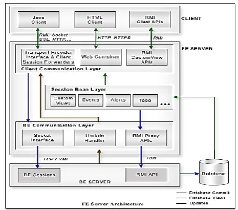
The front-end server is an extension of the back-end server and is designed to provide scalability. Multiple FEs can be connected to a BE and each FE can have multiple clients connected to it in a distributed setup. The main function performed by the FE is to channel the requests received from the clients. The FE takes care of generating the database views through database read operations using a completely stateless architecture. This helps in providing the accurate information at all times.
Components Overview
Client Communication Layer
The client communication layer provides option to choose from a range of transport protocols, such as TCP, RMI, HTTP, HTTPS, SSL, etc. To support various set of clients, such as the Java (session based) client, the HTML client, the RMI (Client API based) clients, etc., the client communication has a rich set of components with each receiving and decoding the requests from the corresponding clients and forwarding them to the Session Beans.
Transport Provider interface & Client Session Forwarders Interacts with the Java client and redirects the read requests to the Session Beans and the database commit requests to the back-end server.
Web Container interface: Provides Web access to the clients and handles all the requests from the HTML client and forwards the request to the Session Beans.
RMI server API interface: Provides APIs for generation of custom views and handles all read operations for the RMI Client APIs using the Session Beans.
Session Bean Layer
The Session Bean layer forms the core business logic of the front-end server. This stateless EJB deployable Session Bean layer generates views from the database (Custom Views) based on the client requests. Forwards the commit requests to the back-end server using the front-end RMI proxy APIs.
Back-End Communication Layer
The back-end communication layer forwards the database commit request generated from the clients to the back-end server and notifies the subscribed clients for any updates from the back-end server. This layer too has different set of interfaces for communicating with the back-end server.
Updates Handler handles all the updates or notifications from the back-end server and forwards them to the clients subscribed for receiving such notifications.
Back-end Socket Interface forwards the database commit requests to the corresponding back-end server through the socket connection.
RMI Proxy API forwards the write requests to the corresponding back-end server module RMI API counterpart.
Figure 1: End Server
Maintaining Security Between Front-End and Back-End Servers
These parameters are optional and by default are not included in the ics. conf file. To use authentication for DWP connections, you must add the required parameters to the ics. conf file on each front-end and back-end server.
Table 1 Back-end Configuration Parameters for Authentication of a DWP Connection
Parameter Description
service.dwp.admin.userid On a back-end server, specifies the user ID that is used to authenticate a DWP connection. If a back-end server does not specify a user ID, no authentication is performed.
service.dwp.admin.cred On a back-end server, specifies the password that is used to authenticate a DWP connection. If a back-end server does not specify a password, no authentication is performed.
Table 2 Front-end Configuration Parameters for Authentication of a DWP Connection
Parameter Description
caldb.dwp.server. back-end-server.admin
On a front-end server, specifies the user ID that is used for authentication for a DWP connection to a back-end server, where back-end-server is the name of the server.
caldb.dwp.server. back-end-server.cred
On a front-end server, specifies the password that is used for authentication for a DWP connection to a back-end server, where back-end-server is the name of the server.
Figure 2 : Server Architecture
2.2 Congestion Control
The final main aspect of TCP is
congestion control
. TCP uses a number of mechanisms to achieve high performance and avoidcongestion collapse
, where network performance can fall by several orders of magnitude. These mechanisms control the rate of data entering the network, keeping the data flow below a rate that would trigger collapse. They also yield an approximatelymax-min fair
allocation between flows.[13]Acknowledgments for data sent, or lack of acknowledgments, are used by senders to infer network conditions between the TCP sender and receiver. Coupled with timers, TCP senders and receivers can alter the behavior of the flow of data. This is more generally referred to as congestion control and/or network congestion avoidance.
Modern implementations of TCP contain four intertwined algorithms:
Slow-start
,congestion
avoidance
,fast retransmit
, andfast recovery
(RFC
5681
).In addition, senders employ a retransmission timeout (RTO) that is based on the estimated
round-trip time
careful when calculating RTT samples for retransmitted packets; typically they use
Karn's Algorithm
or TCP timestamps (seeRFC 1323
). These individual RTT samples are then averaged over time to create a Smoothed Round Trip Time (SRTT) usingJacobson
's algorithm. This SRTT value is what is finally used as the round-trip time estimate.Enhancing TCP to reliably handle loss, minimize errors, manage congestion and go fast in very high-speed environments are ongoing areas of research and standards development. As a result, there are a number of
TCP congestion avoidance algorithm
variations.1) Maximum segment size
The
maximum segment size
(MSS) is the largest amount of data, specified in bytes, that TCP is willing to receive in a single segment. For best performance, the MSS should be set small enough to avoidIP
fragmentation
, which can lead to packet loss and excessive retransmissions. To try to accomplish this, typically the MSS is announced by each side using the MSS option when the TCP connection is established, in which case it is derived from themaximum
transmission unit
(MTU) size of thedata link layer
of the networks to which the sender and receiver are directly attached. Furthermore, TCP senders can usepath MTU discovery
to infer the minimum MTU along the network path between the sender and receiver, and use this to dynamically adjust the MSS to avoid IP fragmentation within the network.[15]MSS announcement is also often called "MSS negotiation". Strictly speaking, the MSS is not "negotiated" between the originator and the receiver, because that would imply that both originator and receiver will negotiate and agree upon a single, unified MSS that applies to all communication in both directions of the connection. In fact, two completely independent values of MSS are permitted for the two directions of data flow in a TCP connection.
[17]
This situation may arise, for example, if one of the devices participating in a connection has an extremely limited amount of memory reserved (perhaps even smaller than the overall discovered Path MTU) for processing incoming TCP segments.[4]2) Selective acknowledgments
Relying purely on the cumulative acknowledgment scheme employed by the original TCP protocol can lead to inefficiencies when packets are lost. For example, suppose 10,000 bytes are sent in 10 different TCP packets, and the first packet is lost during transmission. In a pure cumulative acknowledgment protocol, the receiver cannot say that it received bytes 1,000 to 9,999 successfully, but failed to receive the first packet, containing bytes 0 to 999. Thus the sender may then have to resend all 10,000 bytes.
To alleviate this issue TCP employs the selective acknowledgment (SACK) option, defined in
RFC 2018
, which allows the receiver to acknowledge discontinuous blocks of packets which were received correctly, in addition to the sequence number of the last contiguous byte received successively, as in the basic TCP acknowledgment. The acknowledgement can specify a number of SACK blocks, where each SACK block is conveyed by the starting and ending sequence numbers of a contiguous range that the receiver correctly received. In the example above, the receiver would send SACK with sequence numbers 1000 and 9999. The sender would accordingly retransmit only the first packet (bytes 0 to 999).A TCP sender can interpret an out-of-order packet delivery as a lost packet. If it does so, the TCP sender will retransmit the packet previous to the out-of-order packet and slow its data delivery rate for that connection. The duplicate-SACK option, an extension to the SACK option that was defined in
RFC 2883
, solves this problem. The TCP receiver sends a D-ACK to indicate that no packets were lost, and the TCP sender can then reinstate the higher transmission-rate.3) Window scaling
Main article: TCP window scale option
For more efficient use of high bandwidth networks, a larger TCP window size may be used. The TCP window size field controls the flow of data and its value is limited to between 2 and 65,535 bytes.
Since the size field cannot be expanded, a scaling factor is used. The TCP window scale option, as defined in RFC 1323, is an option used to increase the maximum window size from 65,535 bytes to 1 gigabyte. Scaling up to larger window sizes is a part of what is necessary for TCP tuning.[4]
The window scale option is used only during the TCP 3-way handshake. The window scale value represents the number of bits to left-shift the 16-bit window size field. The window scale value can be set from 0 (no shift) to 14 for each direction independently. Both sides must send the option in their SYN segments to enable window scaling in either direction.[5]
Some routers and packet firewalls rewrite the window scaling factor during a transmission. This causes sending and receiving sides to assume different TCP window sizes. The result is non-stable traffic that may be very slow. The problem is visible on some sites behind a defective router.[18]
2.3 DROP TAIL
Tail Drop, or Drop Tail, is a very simple queue management algorithm used by Internet routers, e.g. in the network schedulers, and network switches to decide when to drop packets. In contrast to the more complex algorithms like RED and WRED, in Tail Drop the traffic is not differentiated. Each packet is treated identically. With tail drop, when the queue is filled to its maximum capacity, the newly arriving packets are dropped until the queue has enough room to accept incoming traffic.[5]
The name arises from the effect of the policy on incoming datagrams. Once a queue has been filled, the router begins discarding all additional datagrams, thus dropping the tail of the sequence of datagrams. The loss of datagrams causes the TCP sender to enter slow-start,
sender begins to receive acknowledgements again and increases its congestion window. A more severe problem occurs when datagrams from multiple TCP connections are dropped, causing global synchronization; i.e. all of the involved TCP senders enter slow-start.[5] This happens because, instead of discarding many segments from one connection, the router would tend to discard one segment from each connection.
III.
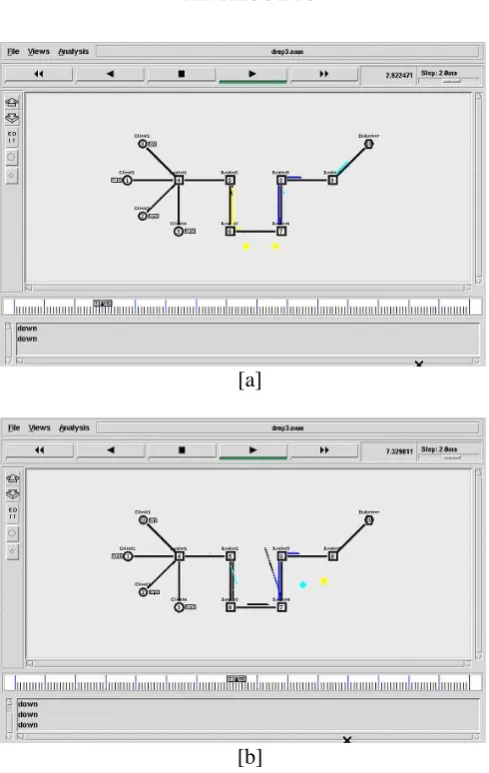
RESULTS
[a]
[b]
Figure 3: Snapshot of the System
Source Code
#---Event scheduler object creation---#
set ns [ new Simulator]
#--- CREATING NAM OBJECTS ---#
set nf [open drop3.nam w] $ns namtrace-all $nf
$ns trace-all $nt set proto rlm
#---COLOR DESCRIPTION---#
$ns color 1 red $ns color 2 blue $ns color 3 yellow $ns color 4 cyan $ns color 5 maroon
# --CREATING CLIENT - ROUTER -ENDSERVER NODES----#
set Client1 [$ns node] set Client2 [$ns node] set Client3 [$ns node] set Client4 [$ns node] set Router1 [$ns node] set Router2 [$ns node] set Router3 [$ns node] set Router4 [$ns node] set Router5 [$ns node] set Router6 [$ns node] set Endserver1 [$ns node] #set Endserver2 [$ns node]
# ---CREATING DUPLEX LINK ---#
$ns duplex-link $Client1 $Router1 5Mb 50ms DropTail $ns duplex-link $Client2 $Router1 5Mb 50ms DropTail $ns duplex-link $Client3 $Router1 5Mb 50ms DropTail $ns duplex-link $Client4 $Router1 5Mb 50ms DropTail $ns duplex-link $Router1 $Router2 5Mb 50ms DropTail $ns duplex-link $Router2 $Router3 150Kb 50ms DropTail $ns duplex-link $Router3 $Router4 300Kb 50ms DropTail $ns duplex-link $Router4 $Router5 100Kb 50ms DropTail $ns duplex-link $Router5 $Router6 300Kb 50ms DropTail $ns duplex-link $Router6 $Endserver1 300Kb 50ms DropTail #$ns duplex-link $Router6 $Endserver2 300Kb 50ms DropTail
#---CREATING ORIENTATION ---#
$ns duplex-link-op $Client1 $Router1 orient down-right $ns duplex-link-op $Client2 $Router1 orient right $ns duplex-link-op $Client3 $Router1 orient up-right $ns duplex-link-op $Client4 $Router1 orient up $ns duplex-link-op $Router1 $Router2 orient right $ns duplex-link-op $Router2 $Router3 orient down $ns duplex-link-op $Router3 $Router4 orient right $ns duplex-link-op $Router4 $Router5 orient up $ns duplex-link-op $Router5 $Router6 orient right $ns duplex-link-op $Router6 $Endserver1 orient up-right #$ns duplex-link-op $Router6 $Endserver2 orient right
# ---LABELLING ---#
$ns at 0.0 "$Client1 label Client1" $ns at 0.0 "$Client2 label Client2" $ns at 0.0 "$Client3 label Client3" $ns at 0.0 "$Client4 label Client4" $ns at 0.0 "$Router1 label Router1" $ns at 0.0 "$Router2 label Router2" $ns at 0.0 "$Router3 label Router3" $ns at 0.0 "$Router4 label Router4" $ns at 0.0 "$Router5 label Router5" $ns at 0.0 "$Router6 label Router6"
$ns at 0.0 "$Endserver1 label Endserver" #$ns at 0.0 "$Endserver2 label Endserver2"
# --- CONFIGURING NODES ---#
$Endserver1 shape hexagon $Router1 shape box $Router2 shape square $Router3 shape square $Router4 shape square $Router5 shape square $Router6 shape square
# ---ESTABLISHING QUEUES ---#
$ns duplex-link-op $Client1 $Router1 queuePos 0.1 $ns duplex-link-op $Client2 $Router1 queuePos 0.1 $ns duplex-link-op $Client3 $Router1 queuePos 0.5 $ns duplex-link-op $Client4 $Router1 queuePos 0.5 $ns duplex-link-op $Router1 $Router2 queuePos 0.1 $ns duplex-link-op $Router2 $Router3 queuePos 0.1 $ns duplex-link-op $Router3 $Router4 queuePos 0.1 $ns duplex-link-op $Router4 $Router5 queuePos 0.1 $ns duplex-link-op $Router5 $Router6 queuePos 0.5 $ns duplex-link-op $Router6 $Endserver1 queuePos 0.5
# ---ESTABLISHING COMMUNICATION ---#
#--- CLIENT1 TO ENDSERVER ---#
set tcp0 [new Agent/TCP] $tcp0 set maxcwnd_ 16 $tcp0 set fid_ 4
$ns attach-agent $Client1 $tcp0
set sink0 [new Agent/TCPSink] $ns attach-agent $Endserver1 $sink0
$ns connect $tcp0 $sink0
set ftp0 [new Application/FTP] $ftp0 attach-agent $tcp0
$ns add-agent-trace $tcp0 tcp $tcp0 tracevar cwnd_
$ns at 0.5 "$ftp0 start" $ns at 28.5 "$ftp0 stop"
# --- CLIENT2 TO ENDSERVER ---#
set tcp1 [new Agent/TCP] $tcp1 set fid_ 2
$tcp1 set maxcwnd_ 16 $ns attach-agent $Client2 $tcp1
set sink1 [new Agent/TCPSink] $ns attach-agent $Endserver1 $sink1
set ftp1 [new Application/FTP] $ftp1 attach-agent $tcp1
$ns add-agent-trace $tcp1 tcp1 $tcp1 tracevar cwnd_
$ns at 0.58 "$ftp1 start" $ns at 28.5 "$ftp1 stop"
# --- CLIENT3 TO ENDSERVER ---#
set tcp2 [new Agent/TCP] $tcp2 set fid_ 0
$tcp2 set maxcwnd_ 16 $tcp2 set packetsize_ 100 $ns attach-agent $Client3 $tcp2 set sink2 [new Agent/TCPSink] $ns attach-agent $Endserver1 $sink2 $ns connect $tcp2 $sink2
set ftp2 [new Application/FTP] $ftp2 attach-agent $tcp2 $ns add-agent-trace $tcp2 tcp2 $tcp2 tracevar cwnd_
$ns at 0.65 "$ftp2 start" $ns at 28.5 "$ftp2 stop"
#---CLIENT4 TO ENDSERVER---#
set tcp3 [new Agent/TCP] $tcp3 set fid_ 3
$tcp3 set maxcwnd_ 16 $tcp2 set packetsize_ 100 $ns attach-agent $Client4 $tcp3
set sink3 [new Agent/TCPSink] $ns attach-agent $Endserver1 $sink3
$ns connect $tcp3 $sink3
set ftp3 [new Application/FTP] $ftp3 attach-agent $tcp3
$ns add-agent-trace $tcp3 tcp3 $tcp3 tracevar cwnd_
$ns at 0.60 "$ftp3 start" $ns at 28.5 "$ftp3 stop"
#---Creating drops---#
$ns rtmodel-at 2.880511 down $Router3 $Router4 $ns rtmodel-at 2.880511 up $Router3 $Router4
$ns rtmodel-at 7.299242 down $Router5 $Router6 $ns rtmodel-at 7.299242 up $Router5 $Router6
# --- FINISH PROCEDURE ---# proc finish {} {
global ns nf nt $ns flush-trace close $nf
puts "running nam..." exec nam drop3.nam &
exit 0 }
#Calling finish procedure $ns at 15.0 "finish" $ns run
IV.
CONCLUSION
This paper is implement by using network simulator tool 2.35 version to show that how packet loss is measured between 2 network circuit and which one is better by comparing the trace file of both the result such that 2 networks are created namely 1- packet loss within same link at particular interval of time and 2- packet loss between different nodes within same link at specific interval of time. Finally we are able to prove that packet loss at particular interval of time is much more effective as compare to specific interval.
V.
REFERENCES
[1] Kompella, K., Rekhter, Y., Berger, L., Link
Bundling in MPLS Tra_c Engineering (TE) IETF Request for Comments: 4201, 2005.
[2] Vasseur, JP., Leroux, JL., Yasukawa, S., Previdi,
S., Psenak, P., Mabbey, P.Routing Extensions for Discovery of Multiprotocol (MPLS) Label Switch Router(LSR) Traffic Engineering (TE) Mesh Membership IETF Request for Comments:4972, 2007
[3] Andersson, L., Asati, R., Multiprotocol Label
Switching (MPLS) Label Stack Entry: "EXP" Field Renamed to "Tra_c Class" Field. IETF Request for Comments:5462, 2009.
[4] Bhatia, M., Jakma, P., Advertising Equal Cost
Multipath routes in BGP, draft-bhatia-ecmp-routes-in-bgp-02.txt IETF Internet Draft, 2006.
[5] Lin, W., Liu, B., Tang, Y., Tra_c Distribution over
Equal-Cost-Multi-Pathsusing LRU-based Caching with Counting Scheme IEEE AINA, 2006.
[6] Martin, R., Menth, M., Hemmkeppler, M.,
Accuracy and Dynamics of Hash-Based Load Balancing Algorithms for Multipath Internet
Routing. IEEE Conference on Broadband
[7] Kandula, S., Katabi, D., Sinha, S., Berger, A., Dynamic Load Balancing With-out Packet
Reordering ACM SIGCOMM Computer
Communication Review 54 Volume 37, Number 2, 2007.
[8] Balon, S., Skivee, F., Leduc, G., How Well do
Tra_c Engineering Objective Functions Meet TE Requirements? IFIP Networking, LNCS 3976, pp. 75{86, 2006.
[9] Lada A. Adamic, Rajan M. Lukose, Bernardo
Huberman, and Amit R. Puniyani Search in Power-Law Networks, Phys. Rev. E, 64 46135 (2011)
[10] Dejan Kostic, Adolfo Rodriguez, Jeannie
Albrecht, and Amin Vahdat, Bullet: High Bandwidth Data Dissemination Using an Overlay Mesh, In Proc. ACM SOSP 2013
[11] Russ Cox, Frank Dabek, Frans Kaashoek, Jinyang
Li, and Robert Morris Practical, Distributed Network Coordinates HotNets 2013
[12] Ayalvadi J. Ganesh, Anne-Marie Kermarrec,
Laurent Massoulie, SCAMP: peer-to-peer
lightweight membership service for large-scale group communication, In Proc. 3rd Intnl. Wshop Networked Group Communication (NGC’01), pages 44–55. LNCS 2233, Springer, 2010
[13] Ayalvadi J. Ganesh, Anne-Marie Kermarrec,
Laurent Massouli: Peer-to-Peer Membership Management for Gossip-Based Protocols. IEEE Trans. Computers 52(2):139-149 (2013)
[14] Q. Lv, P. Cao, E. Cohen, K. Li, and S. Shenker.
Searchand replication in unstructured peer-to-peer networks In ICS’02, New York, USA, June 2012
[15] Christos Gkantsidis, Milena Mihail, and Amin
Saberi, Random Walks in Peer-to-Peer Networks, to appear in IEEE Infocom 2014
[16] Yatin Chawathe, Sylvia Ratnasamy, Lee Breslau,
Nick Lanham, and Scott Shenker, Making Gnutella-like P2P Systems Scalable, In Proc. ACM SIGCOMM 2003, Karlsruhe, Germany, Aug 2013.
[17] C. Law and K.-Y. Siu, Distributed construction of
random expander networks, In Proc. IEEE Infocom 2013
[18] Gopal Pandurangan, Prabhakar Raghavan, and Eli
Upfal, Building low-diameter p2p networks, In STOC 2011, Crete, Greece, 2011
[19] I. Clarke, O. Sandberg, B. Wiley, and T.W. Hong,
Freenet: A distributed anonymous information
storage and retrieval system, In Proc. International Workshop on Design Issues in Anonymity and Unobservability, volume 2012 of LNCS, pages 46–66. Springer-Verlag, 2012
[20] Ziv Bar-Yossef, Alexander Berg, Steve Chien,
Jittat Fakcharoenphol, and Dror Weitz,
Approximating Aggregate Queries about Web Pages via Random Walks, In Proc.VLDB 2014.
VI.
Author’s Profile
Dr. Rajdev Tiwari having work experience of more than 16yr. Completed phd from Computer Science in 2012 from Dr. B.R ambedkar University AGRA. Completed Master of Computer Application in 2005 from Indra Gandhi National Open University. Also completed Master of Science in 1997 from Dr. Rammanohar Lohia Awadh University Faizabad