R E S E A R C H
Open Access
Bounded model checking for fixed-point
digital filters
Renato B. Abreu
1, Mikhail Y. R. Gadelha
2, Lucas C. Cordeiro
3*, Eddie B. de Lima Filho
4and Waldir S. da Silva Jr
3Abstract
Background: Currently, digital filters are employed in a wide range of signal processing applications, using fixed- and floating-point processors. Regarding the former, some filter implementations may be highly prone to errors, due to problems related to finite word-length. In particular, signal processing modules may produce overflows and unwanted noise, which are caused by quantization and round-off effects, during accumulative-addition and multiplication operations. As a consequence, the system output may overflow or even keep oscillating, which compromises the expected system performance.
Methods: The present paper addresses this problem and proposes a new methodology for verifying digital filters, called digital systems verifier, which is based on state-of-the-art bounded model checkers that support full C and employ solvers for boolean satisfiability and satisfiability modulo theories. In addition to verifying overflow and limit-cycle occurrences, the present approach can also check output errors and time constraints, based on discrete-time models implemented in C.
Results: Experiments conducted during this work show that the proposed methodology is effective, when finding realistic design errors with respect to fixed-point implementations of digital filters.
Conclusions: Going further than previous attempts, the present results suggest that the proposed method, in addition to helping designers in determining the number of bits for fixed-point representations, can also aid in defining details about filter realization and structure.
Keywords: Digital filters, Finite word-length, Formal methods, Bounded model checking
Introduction
In digital signal processing, a digital filter is a system that performs operations on discrete signals, in order to modify or improve some of their aspects. It can be clas-sified into two types: infinite impulse response (IIR) or finite impulse response (FIR), differing by the presence or absence of feedback, respectively. One of the most com-mon procedures performed by digital filters, for instance, is to narrow or shape signal bandwidths, with the goal of discarding undesired information.
Digital filters have been used in a great variety of applications, mainly due to their reduced computational complexity and flexibility, which is reinforced by the avail-ability of digital signal processor (DSP) and field pro-grammable gate array (FPGA) devices. Regarding the first,
*Correspondence: [email protected]
3Federal University of Amazonas, Manaus, Amazonas, Brazil Full list of author information is available at the end of the article
they are split into two categories: fixed- and floating-point, which refer to the format used for storing and processing numerical-data representations. In fixed-point arithmetic, gaps between adjacent number representa-tions are normally equal; floating-point arithmetic, in turn, results in nonuniform gaps, which are about ten million times smaller than a given number magnitude, depending on the floating point precision [1].
Typically, dynamic range, precision, ease of develop-ment, and cost considerations are used for determining the most interesting approach. For example, fixed-point devices provide low-cost products and normally incur higher development costs, which are suitable for high-volume applications; however, floating-point devices result in higher product costs, while presenting shorter development cycles and higher precision, which may be acceptable for high-value applications. In summary, the
data to be processed and the target application define the need for fixed- or floating-point processors.
It is worth noticing that even with the current increased-availability of floating-point devices, which may also include optimized modules for complex-number manipu-lation, the high speed of fixed-point processors, in com-bination with their reduced cost, still make them a good choice for embedded digital filter design.
Both fixed- and floating-point implementations suf-fer from quantization errors; however, the latter nor-mally presents better precision and higher dynamic range. Indeed, larger gaps in fixed-point approaches result in smaller signal-to-noise ratio (SNR) figures, and, due to that, nonlinearities, round-off errors, and overflows are much more pronounced, all caused by consecutive mul-tiplication and addition operations using finite word-length, which might affect the desired filter behavior. For instance, regarding direct form realizations, only a small change on filter coefficients, due to quantization, has the potential to cause large changes in pole and zero locations [2].
In addition, different filter types present different prob-lems. For example, IIR filters might suffer from serious oscillations in their outputs, even for zero input signals,
which is a phenomenon known as limit cycle [3–6]. In
summary,limit cyclesare oscillations that appear due to
rounding, truncation or overflow (nonlinearities), regard-ing internal filter computations, even if a given filter is stable, due to the feedback branch. FIR filters, in turn, do not suffer from such limit cycle effects, but might have other issues caused by finite word-length limitations (e.g., frequency response modification).
There are many studies about quantization and limit cycle effects in digital filters, along with techniques to reduce their effects [7] or guarantee their absence [8–11]. Generally, limit cycles can be avoided by increasing the system word-length or applying scaling and saturation; however, those solutions present some drawbacks. The first may extrapolate the representation provided by the underlying architecture, and the second has the potential to decrease the SNR. As a consequence, the related error magnitude should then be verified, in order to ensure that it is at an acceptable level. It is also possible to use noise shaping [12], where quantization errors go through a feed-back loop and, consequently, a very high SNR ratio is obtained, which greatly reduces limit cycle occurrences.
Another important property, which arises when imple-menting digital filters for real-time applications, is the time constraint [13]. In a real-time system, which may consist of other tasks beyond simple filtering, high sam-ple rates will require more processing resources; there-fore, the use of high sample rates may be insufficient to execute tasks and may also degrade the expected sys-tem performance. Indeed, time constraints verification
is of paramount importance for real-time systems and, although not directly related to digital filters, it is often addressed during their design, in order to ensure the desired system behavior.
Normally, filter designers employ advanced tools for defining filter parameters, according to the desired oper-ation in time and frequency domains, and use simuloper-ation software for validating their behavior, along with extensive testing. However, in most cases, floating-point arithmetic is considered during calculations, which can lead to wrong assumptions about filter performance.
There are a few tools for simulating systems using fixed-point arithmetic [14–16], which can be employed during filter design. As an example, Sung and Kum [17] proposed search algorithms to determine the min-imum word-length bound, through a simulation-based approach. Nguyen, Menard, and Sentieys [18] also pro-posed faster word-length optimization algorithms, when compared to Sung and Kum’s approach, which are based on iterative stochastic local searches. However, simulation (and testing) can lead to a limited number of scenarios and inputs, which normally do not exploit all possible behaviors that a system can exhibit and take long to com-plete. Analytical approaches may also be employed [19], which significantly reduces evaluation times. Hence, just performing frequency domain graphical analysis and sim-ulations might not be enough to discover possible prob-lems related to finite word-length, as well as filter time constraints.
Recently, Cox et al. [20, 21] proposed the verification of fixed-point implementations of IIR digital filters, which is based on bounded model checking (BMC) [22] and applies modern satisfiability modulo theory (SMT) [23] solvers, in order to check for verification conditions. The main idea behind SMT-based BMC approaches is to
con-sider counterexamples of a particular length kand then
generate an SMT formula, which is satisfiable if and only if such a counterexample exists [24, 25].
Contributions
The present paper addresses the digital-filter verifica-tion problem and describes the use of a general purpose SMT-based bounded model checker for C programs, in order to verify potential problems caused by fixed-point arithmetic, on recursive filters.
be embedded into micro-controllers and DSPs. It is worth noticing that the latter is closer to real implementations, where specific C constructs (e.g., pointer arithmetic and comparisons) are used for implementing digital filters. The resulting C code also gives the possibility to apply other (state-of-the-art) model checking techniques (for C programs) to general filter verification.
Additionally, the application of SMT-based BMC approaches, regarding digital filter design, is not well known amongst DSP developers, which also opens a great opportunity, since SMT-based BMC approaches do not require proof (i.e., they are algorithmic methods rather than deductive) and are very fast, if compared with other rigorous methods, such as theorem proving. Besides, one can easily specify a large number of digital filter proper-ties and realization forms, in order to ensure correctness in computer-based systems (e.g., DSP and FPGA).
This article is a substantially revised and extended version of the work published in previous conferences [26, 27]. The major differences are the following: (1) in this version, an enhanced fixed-point library for arith-metic operations was implemented, in order to decrease verification-time figures, (2) other filter structures in cascade, parallel, and transposed direct forms are sup-ported, (3) a maximum-error verification procedure was added, (4) a unified tool, named as digital systems
veri-fier (DSVeriveri-fier1), which developed for checking different
design problems in fixed-point digital filters, was built, (5) two different state-of-the-art BMC tools were used in DSVerifier as back-ends (i.e., CBMC [28] and ESBMC [24]), and (6) the performed experiments are based on a set of publicly available benchmarks. All benchmarks, tools, and results of the present evaluation are available on
a supplementary web page2.
The remainder of this paper is organized as fol-lows. “Verification of digital filters” Section gives a brief introduction about digital filter realizations, emphasiz-ing some aspects related to implementation in fixed-point processors, along with state-of-the-art verification schemes presented in the related literature. Fundamen-tals about SMT-based BMC approaches, which were used in this work to the verification of digital filters, are tackled in “Bounded model checking (BMC)” Section. “Research design and methodology” Section describes the research design and respective methodology, while “Methods” Section presents the implemented methods to verify overflow, limit cycle, time constraint, and maximum error. Then, some experimental results for a set of digital filters, obtained with the proposed approach, are shown in “Results and discussion” Section. Finally, “Conclusions” Section presents the conclusions of this work, highlighting the importance of SMT-based BMC approaches for the verification of fixed-point filters.
Background and literature review Verification of digital filters
As already mentioned, finite word-length effects are of paramount importance for digital filter design, given that numerical implementations of the related algorithms may suffer from deterioration in performance. The follow-ing sections will tackle filter implementation structures and some state-of-the-art verification algorithms, with the goal of introducing the basic problem.
Fixed-point filters realization
Digital filters can be defined as linear time-invariant discrete-time systems, which are described by a difference equation as
y(n)= − N
k=1
aky(n−k)+ M
k=0
bkx(n−k), (1)
wherey(n)is the output in instantn,y(n−k)is the output
ksteps in the past,x(n−k)is the inputksteps in the past,
akare the coefficients for the past outputs,bkare the
coef-ficients for the past inputs,Nis the feedback filter order,
andMis the feedforward filter order. The proper design of
a digital filter consists in finding suitable values for
coef-ficientsakandbk, which produce the expected frequency
response.
Digital filters are usually classified according to their ideal frequency domain characteristics, whose basic forms are low-pass, high-pass, band-pass, and band-reject. It is out of scope for this paper to show IIR and FIR filter design methods, because this is a huge topic that is covered in standard digital signal processing books [2, 29].
There are many ways to implement (1) in hardware, using FPGA and application-specific integrated circuits, or in software, through a programmable digital computer, depending on the desired realization structure for the tar-get system. The commonly known Direct Form I, Direct Form II, and Transposed Direct Form II structures are
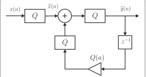
shown in Fig. 1, where z−1 is defined as the
backward-shift operator, that is, a unit delay. These second-order structures are often employed as basic building blocks of high-order systems, in cascade and parallel [2].
When implementing fixed-point digital filters, coef-ficients and results of intermediate computations are affected by quantization and round-off errors. Here, the
round-off quantizerQ(x)was considered [2, 29], whose
maximum error caused by rounding is defined to be
2−b−1, wherebis the number of bits of the fractional part.
If the result from an addition or multiplication exceeds the amount of bits available for the number
representa-tion, it is assumed that anoverflowoccurs. However, for
Fig. 1Second-order modules
Fig. 2Round-off quantizer oflprecision bits, with wrap around overflow
behavior of the round-off quantizer and the effect of a two’s complement overflow wrapping around.
In order to obtain a realistic model of the finite precision system, each numeric value in the system is quantized, which includes inputs, coefficients, and results of arith-metic operations. Figure 3 shows this approach for a single-pole filter.
Typically, numbers in fixed-point format are repre-sented with a pair of digits, which are separated by a decimal point. The digits to the left and right repre-sent the integer and fractional parts, respectively, and the two’s complement is used to represent signed num-bers, in fixed-point processors. In this system, the real
number X, described by the k,l fixed-point position
number bk−1bk−2 . . . b1b0 · b−1b−2 . . .b−l, can be
represented as
X= −bk−12k−1+
−l
i=k−2
bi2i. (2)
The most significant bit −bk−1 is used for the sign.
Thus, the maximum representable value, which consists
of an integer part with k bits and a fractional part with
l bits, is 2k−1− 2−l, and the minimum value is−2k−1.
In Fig. 3, the quantizer Q rounds numbers inside this
range. If a number does not fit into this interval, then it
indicates anoverflow, which can be handled in the follow-ing ways, by the verification module: detect it as failure, wrap around results, or saturate to a maximum/minimum value. Although saturating implementations are popu-lar in DSPs, we handle both saturating and wrap-around math.
Given that fixed-point implementations introduce quantization effects and reduce dynamic range figures, traditional simulation and test steps for system verifica-tion may not be enough, because they normally exploit only a limited number of scenarios and variable values. Moreover, filter designers usually adopt floating-point tools for evaluating their projects, which has the poten-tial to let some failures go unnoticed. As a result, one can argue that detecting problems caused by fixed-point implementations, regarding digital filters, is a challenge that deserves formal verification-methods.
Finite word-length effects in digital filters
Target systems for implementing digital signal processing applications, like DSP and FPGA devices, are not capa-ble of computing with infinite precision and commonly use finite word length, which leads to deterioration in performance. Such an effect has two separate origins: quantization and roundoff errors during computations [30].
One of the most known problems related to finite word-length is the overflow/underflow condition, which can compromise results in recursive filters. As stated in the related literature [2, 29], a filter output can be computed with the convolution sum, given as
y(n)= ∞
k=−∞
x(n−k)h(k), (3)
where x(n) is the input, h(k) is the impulse response
of the filter, and y(n) is the output. Given that the
present approach addresses input
bounded-output (BIBO) stable systems, and that the input is in
the interval [−xmax,xmax], the output is then limited in
amplitude [2, 29], according to
|y(n)| ≤xmax ∞
k=−∞
|h(n)|, (4)
which implicitly employs the L-1 norm, given by
||h||1=
∞
k=−∞
|h(n)|. (5)
This way, overflows can be avoided by using a rep-resentation capable of accommodating the signal range
related toy(n). Since such a rule is very conservative and
the roundoff noise may be unnecessarily increased [31], for instance, the L-2 norm may also be employed, but
it does not guarantee the complete absence of overflow conditions [32].
It is worth noticing that even taking into account what was presented above, any intermediate addition, in a dig-ital filter, may still overflow; however, as long as two’s complement arithmetic is used, it does not affect the final result of summations. Indeed, since the 2’s complement is a modulo math, if intermediate operations overflow, the associated system will still produce correct outputs, as long as the final result falls into the expected range, even if one of the operands has overflowed, due to a mul-tiplication. That implies the addition of more than two numbers, as long as their output is representable. Such a property is commonly known as the Jackson’s rule [33, 34] and is extensively used in digital filters, in order to sim-plify designs and minimize word lengths, given that all quantizers are configured to wrap around.
Regarding Fig. 1, an important observation must be made. Parts (a) and (c) of the same figure show that multi-plier outputs are directly fed to unique equivalent adders (disregarding delays), which means that Jackson’s rule is valid. Part (b), in turn, shows two equivalent adders (input
and output), connected through a multiplier (b0), which
also means that Jackson’s rule is valid; however, the out-put of the equivalent inout-put adder must not overflow. If that is not avoided, the result of the equivalent output adder may be incorrect. Indeed, each adder result may be seen as the output of a separate filter, which will pro-duce correct results as long as its final computation does not overflow.
In summary, if each component filter is correctly designed and two’s complement with wraparound is employed, Jackson’s rule will apply (as done here). Indeed, practical designs take into consideration the output of existing equivalent adders, in such a way that the resulting filter will not suffer from overflow, independently of inter-mediate operations. Nonetheless, if the result saturates [9], such an assumption is no longer applicable and each node must be evaluated for avoiding overflow conditions [20, 21].
In an ideal stable filter, the output should asymptoti-cally approach a steady-state level, which is determined by the filter transfer function [35]. However, if a limit cycle problem exists, it manifests itself either as a steady oscil-lation or a nonzero level in the output, even for a zero level input. Such an effect is normally caused by round-off errors and overflows, during filter operation, when a feed-back loop is present. Limit cycles may be dominant for low inputs, but their importance is diminished with increasing amplitudes [36].
Limit cycles can be avoided, for instance, when
min-imum L2 sensitivity realizations are employed [37], by
works, available in the related literature, that tackle this problem specifically for saturation arithmetic [11].
Another approach for dealing with fixed-point imple-mentations relies on word-length optimization, in such a way that hardware requirements are minimized, while trying to maintain a desired performance measure. Sung and Kum [17] used search algorithms that keep a desired signal-to-quantization-noise ratio (SQNR); how-ever, results are dependent on the signal input samples, which must be carefully chosen.
Nguyen, Menard, and Sentieys [18] also proposed word-length optimization algorithms, in which the absence of overflows is ensured, in the first step of the algorithm, through analytical determination of data behavior.
There has been great interest also in the computation [41] and analysis [42, 43] of the roundoff noise, in order to study its interaction with the filter output and even provide design tools for minimizing noise power or pole sensitivity.
The finite word-length problem can also be treated by means of a unifying approach [32], which is capa-ble of describing equivalent realizations and measures for designing optimal systems. Although it addresses both implementation- and realization-level, a great deal of effort must still be employed, for the development of suitable optimization algorithms.
Indeed, there is a great deal of techniques available for digital filter analysis and design, which can be applied to many scenarios; however, only a few works (e.g., Hildare’s approach [32]) present a more general methodology, as proposed here.
Bounded model checking (BMC)
The bounded model checking (BMC) techniques, based on Boolean satisfiability (SAT) [22] or satisfiability mod-ule theories (SMT) [23], have been successfully applied for verifying single- and multi-threaded programs, and also for finding subtle bugs in real programs [24, 25, 28, 44]; however, applications aiming to ensure correctness of digital filters are only recent [20, 21].
The basic idea of BMC is to check (the negation of ) a given property at a given depth. Supposing a transition
systemM, a propertyφ, and a boundk, BMC unrolls the
systemktimes and translates it into a verification
condi-tion (VC)ψ, in such a way thatψis satisfiable if and only
ifφ has a counterexample, of depth less than or equal to
k. Given that, standard SMT/SAT solvers can be used to
check whetherψis satisfiable.
In BMC of digital filters, the boundklimits the
num-ber of loop iterations and recursive calls in the filter implementation. BMC thus generates VCs that reflect the exact path in which a statement is executed, the context in which a given function is called, and the bit-accurate representation of expressions [24]. It is worth noticing
that the validity proof, for VCs arising from programs, is still a major performance bottleneck, despite attempts to cope with increasing system complexity, by applying SMT solvers.
In this work, the efficient SMT-based bounded model checker (ESBMC) tool is used as the verification engine, since it was one of the most efficient BMC tools, for bit-vector programs, in the last software verification com-petitions [45–47]. In ESBMC, the associated SMT-based BMC problem is formulated by constructing the logical formula
ψk=I(s0)∧
k
i=0
i−1
j=0
γ (sj,sj+1)∧φ(si), (6)
where φ is a safety property (e.g., overflow represented
as an assert-statement in the C source-code level), I is
the set of initial states ofM, andγsj,sj+1
is the
transi-tion relatransi-tion ofMbetween time stepsjandj+1. Hence,
I(s0)∧ i−j=10γ
sj,sj+1
represents executions of the
fil-ter function, unrolling up to lengthi. The above VCψk
can then be satisfied if and only if, for somei ≤ k, there
exists a reachable state, at time stepi, in whichφ is
vio-lated. If (6) is satisfiable, then the SMT solver provides a satisfying assignment, from which values of program variables can be extracted, in order to construct a
coun-terexample. The latter, for a propertyφ, is then defined as
a sequence of statess0,s1,. . .,sk, withs0∈S0andsk ∈S,
andγ (si,si+1), for 0 ≤i < k. If (6) is unsatisfiable, then
one can concluded that no error state is reachable, ink
steps or less.
Related work on model-checking
There are some model-checking tools that have been used for verifying real-time systems, but not digital filters. An example is UPPAAL [48], which is a model checker based on the timed automata theory, that is, it is applied to real-time systems modeled via a timed automata network. Another similar tool is Open-Kronos [49], which is able to check reachability of timed automata and emptiness of timed Büchi automata. The CPN tools [50] are also applied to the verification of real-time systems, which are modeled via a colored (timed and untimed) Petri net.
they did not exploit different filter design techniques in their benchmarks; there is no check related to the actual C implementation that is going to be embedded into the hardware platform; and finally, they do not exploit dif-ferent state-of-the-art BMC tools for C programs, which have considerably evolved over the last years. Indeed, Cox et al. use the ABC model checker [51], which incorporates a BMC implementation as part of the portfolio solver; however, ABC does not noticeably change results [21].
Research design and methodology
The main goal of the present work is to provide a general scheme for digital filter verification, based on DSVeri-fier [52]. Such an approach is composed of digital-filter verification rules and the verification engine itself.
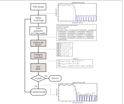
The following steps for design and verification of dig-ital filters are proposed, as shown in Fig. 4. First, filter
parameters are designed, using the preferred methods [2, 29] and tools [53] (cf. Filter design). After that, the output range for a given input is estimated (e.g., based on the cri-teria proposed by Carletta et al. [54]), in order to define the word-length for representing fixed-point numbers (cf. define word length). Once the word-length is defined, the respective design parameters are fed to the filter model implemented in C language, which include number of bits, realization, and sample time (cf. feed parame-ters to C filter-model). Then, one can perform a time analysis regarding filter operations, considering a spe-cific microprocessor architecture, including instruction-set architecture and CPU clock (cf. analyze the WCET). Finally, assertions are added to the given model, in order to check properties related to time constraints, overflow, limit cycle, and output errors (cf. configure assertions). The unwinding bound to run the BMC procedure is
determined according to the filter function, based on the computation of output samples (cf. run BMC).
If any property violation is found, then DSVerifier reports a counterexample, which contains system inputs that lead to the respective system failure (cf. counterex-ample). A successful verification result is reported if the
system is safe with respect toφ, up to boundk(cf. success).
In Fig. 4, white boxes represent actions to be per-formed by the filter designer, while gray boxes represent actions to be performed automatically by DSVerifier (i.e., without filter designer interventions). One can notice that if an under or overflow occurs, a high output error is found. Such information is extracted from a coun-terexample, which is provided by the verification engine, and then the word-length is increased, which is fol-lowed by another call to the verification engine. Alter-natively, if a time constraint violation is found (which is also extracted from the counterexample), then it indi-cates that the filter complexity and the word-length must be decreased, in order to achieve a performance improvement.
It is worth noticing that the timing verification is performed inside the DSVerifier context, by exploiting exhaustive checking via non-deterministic inputs. Indeed, such a verification is very important and must be included in the tool set, since it aids in determining the tradeoff among filter property conformance, fixed-point represen-tation, and hardware requirements.
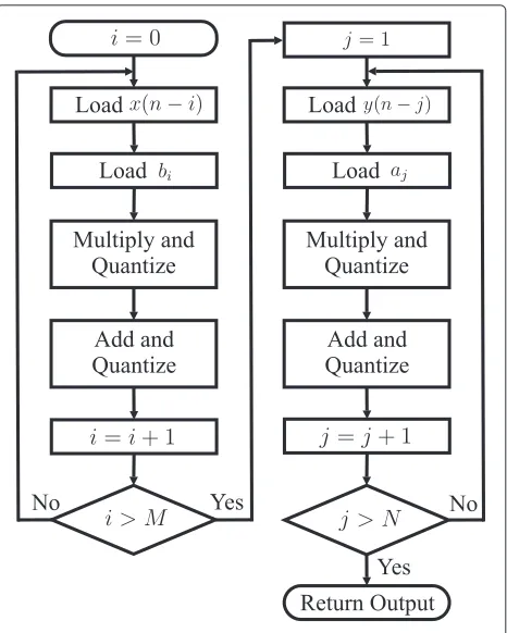
Figure 5 shows an algorithm for a Direct Form I filter, which is implemented as C source-code in DSVerifier, as shown in Fig. 6, so that Eq. 6 can be derived in ESBMC (or CBMC) and checked by an SMT (or SAT)
solver. In Fig. 6, the functions fxp_add, fxp_mult,
andfxp_subtake two input arguments and return the respective addition, multiplication, and subtraction result infxp32_tformat, which is internally defined in
DSVer-ifier asint32_t. The addition and multiplication blocks
also include the quantization effect on the result, consid-ering the fixed-point representation used for the system. The quantizer can be configured to saturation, wrap-around or throw an error, when the result of an operation exceeds its representable limits. Similarly, DSVerifier also implements the filter functions in Direct Form II and Transposed Direct Form II, using the C language and a
fixed-point library3.
In addition, one may notice that the code in Fig. 6 employs pointer arithmetic, instead of normal indexing. From the verification point of view, pointers correspond directly to memory addresses, thus avoiding indexing complexity, while array indexing involves multiplying indexes by the element size and adding such a result to the array base address, which has a higher cost, in terms of verification time. Currently, ESBMC, CBMC, and other state-of-the-art verifiers, regarding C programs, are able
Fig. 5Algorithm of a Direct Form I filter
to efficiently and effectively support pointer arithmetic and comparisons [55].
The main goal of the present study is not proposing advanced methods for digital-filter parameter verifica-tion, but instead incorporating (some) techniques and then provide a general framework for system verification, based on DSVerifier. This way, the employed verification is robustly implemented and enables an iterative scheme for designing and testing digital filter modules.
Illustrative example
As a toy example, which is supposed to fail for illus-trative purposes, a single-pole system, described by the difference equation
y(n)= −a y(n−1)+x(n), (7)
is presented. This is a bounded-input bounded-output
(BIBO) stable system [2, 29], in which the output is lim-ited in amplitude, according to (4). Regarding (7), with
a = −1/2, it can be shown that the summation of the
impulse response norm converges to 2 using geometric
series (i.e.,|hk| = 1−10.5 = 2). In this particular
exam-ple, if an input in the range [−1, 1] is considered, the
output will be [−2, 2] (i.e., the input range is simply
multi-plied by|hk|). Given that one could choose to represent
Fig. 6C code for a Direct Form I filter
according to the classical method described by Carletta et al. [54], it is worth noticing that this is not the only criteria, since there may be restrictions regarding the tar-get hardware, which may even allow a larger number of bits. As a result, the designer must take into account sys-tem restrictions and minimum required number of bits. The resulting range for this particular format would then
be [−2, 1.9375], with an error of±0.03125.
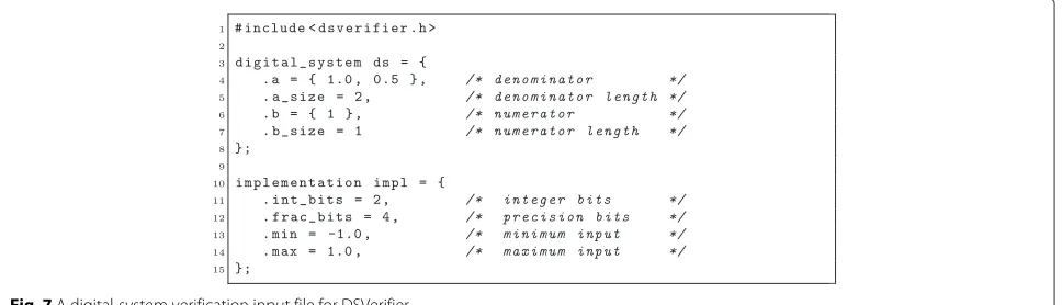
The proposed method can then be employed for veri-fying the proposed setup. The coefficients of (7) are used for the filter model in C language, with the previously defined numeric representation. In DSVerifier, the user must provide the specification in a ANSI-C file, as shown in Fig. 7. This file contains the digital-system specification
(ds), with numerator (ds.b = {1}) and denominator (ds.a=
{1.0, 0.5}), and the implementation specification itself (impl), which contains the number of bits in the integer (impl.int_bits = 2) and fractional (impl.frac_bits = 4) parts, and the input range (impl.min = -1 and impl.max = 1).
The user must also define the realization form (e.g., DFI) and the verification configuration parameters (e.g., solver and timeout). As an example regarding the verification of overflow occurrences, with a timeout of 1 h and a bound
of 10 cycles, the following parameters must be provided to DSVerifier:
dsverifier <filename> -realization DFI -property OVERFLOW
-x-size 10 -timeout 1h -solver boolector
If DSVerifier is run, by taking into account the input
range [−1, 1], then it quickly shows a counterexample
in which the system gets an overflow, for a particular sequence of inputs. For instance, it can be easily shown
that an input sequence x = {1, 1, 1, 1, 1, 1} leads to an
overflow in the output, as reported in Table 1.
The solver adoption depends basically on its cover-age and verification speed. In tests performed with many applications, Boolector [56] and Z3 [57] presented large coverage and reasonable verification times. In addition, all C/C++ language structures used in filter implementations are handled by Boolector and Z3, which makes them good choices. Of course, if filters are developed with different tools or libraries, which are deeper supported by another solver, the designer has the flexibility to change it.
Additionally, an unwinding bound ofk = 10 to unroll
all loops and recursive functions is set, so that a property
Table 1Overflowoccurrence in the toy example
n 1 2 3 4 5 6
x(n) 1 1 1 1 1 1
y(n) 1.0000 1.5000 1.7500 1.8750 1.9375 1.96875
violation is exposed for this particular digital filter imple-mentation; however, since DSVerifier entirely relies on the BMC technique, it is susceptible to exhaustion of time (or memory) limits, when checking digital filters whose unwinding bounds are too large (see our experimental evaluation). Finally, the timeout is an optional parameter to limit the verification time.
Once again, there may be hardware and application restrictions, which will influence the choice regarding realization forms. For example, if there are time restric-tions and many logic cells are available, one may choose to use a parallel structure. Besides, if truncation noise is a concern (i.e., the associated SNR), e.g., when process-ing audio, a DFI is preferred. Finally, if memory cells are a scarce resource, TDFII and DFII are viable options.
For this particular case, one could easily infer about overflow conditions by simply analyzing the impulse response summation or simulating a constant step input; however, it is worth noticing that impulse response summations are useful to infer about intermediate operations.
As a consequence of the overflow reported by DSVeri-fier, the designer then has to re-define the word length. In this particular example, if the number of bits in the inte-ger part (e.g., impl.int_bits = 2) is increased, then the user can rectify the single-pole system implementation and, for this particular word length, the verification is successfully completed.
DSVerifier might also be used via graphical user
inter-face (GUI), which is available in the DSVerifier website4.
More details about the DSVerifier GUI and command-line can be found in the article written by Ismail et al. [52].
The next section presents the methods, which were employed in the proposed approach, for implement-ing the digital filter verifications shown in Section “Finite word-length effects in digital filters”. In addition, there is a deeper discussion about specific features of each verification procedure.
Methods
Arithmetic underflow and overflow verification
During the design of fixed-point filters, one needs to specify the number of integer and fractional bits. First, the output range of the filter, for a given input, must be estimated; such a procedure typically relies on analytical- [58] or simulation-based approaches [7, 17, 18]. Thus, the designer should specify a suitable word-length
for representing variables, considering also quantization errors in the system response.
In the present work, assertions are coded in the quan-tizer block and the verification engine is configured to use non-deterministic inputs, in the specified range, in order to detect overflows in digital filters, for a given fixed-point word-length. For any addition or multiplication results, during filter operation, if there exists a value that exceeds the range representable by the fixed-point approach, an assert statement detects that as an under or overflow
vio-lation. As a consequence, a literal loverflow is generated,
with the goal of representing the validity of each addition and multiplication operation, according to the constraint
loverflow⇔(MIN ≤FP)∧(FP≤MAX), (8)
where FP is the fixed-point approximation [24], for the
result of adders and multipliers, andMIN andMAXare
the minimum and maximum values representable for the given fixed-point bit format, respectively (as previously described in Section “Fixed-point filters realization”). One can notice that constraints are typically included into the
verification engine simply as anassert-statement in the C
source-code level (e.g., assert((MIN ≤ FP) && (FP ≤
MAX))).
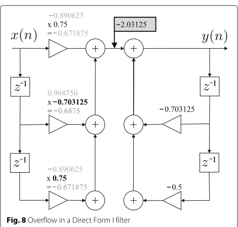
In contrast to our toy example, regarding cases where intermediate operations cause overflow, the filter defined by
y(n)=0.703125y(n−1)−0.5y(n−2)+
0.75x(n)−0.703125x(n−1)+0.75x(n−2) (9)
can illustrate such situations. In this example, it is consid-ered that the fixed-point values are represented with 2 bits for the integer part and 6 bits for the fractional one. The
summation|hk|for this filter converges to 1.8279; this
way, if inputs in the range [−1, 1] are applied to this
sys-tem, it then provides output values that are representable
in the fixed-point range [−2, 1.984375]. When a bounded
verification of this system is performed, with implemen-tations in Direct Form I and Transposed Direct Form II structures, the proposed tool issues a counterexam-ple that causes an overflow on an intermediate operation. Figure 8 illustrates the overflow on the summation after the first stage on the Direct Form I implementation, when the counterexample input is applied to the filter. For the Direct Form II filter, the verification successfully finishes without issuing any overflow failure, due to operation execution-order in this particular case. As a consequence, such observations then reinforce the application of BMC to digital filters, as an auxiliary verification tool.
Fig. 8Overflow in a Direct Form I filter
will still arrive at the correct result. This way, if wrap-around is used, overflow assertions for intermediate operations are simply disabled.
Limit cycle verification
In order to verify the presence of limit cycles, in a par-ticular fixed-point filter realization, the quantizer block routine is configured by setting a flag variable on it, in order to enable wrap around on overflows. The expected behavior will be as shown in Fig. 2, which means that the verification engine is not expected to detect over-flow failures, as in the previous case. Additionally, the filter is configured to use a zero input signal and a non-deterministic initial state, for previous outputs. The filter execution is then unrolled, for a bounded number of entries, and an assert statement is added to detect a fail-ure, if a set of previous outputs states (that repeats during the zero-input response) is found. One can notice that this method is different from the one presented by Cox et al. [20, 21], which aims at finding a limit cycle by compar-ing input and output windows, within a bounded number of steps.
As an example, the same system described by (7) is con-sidered. Here, such a filter is also modeled using 2 bits for the integer part and 4 bits for the fractional one (as in the previous case), but with a zero input signal. If the ver-ification engine is executed for the implemented model, then it finds a particular initial condition that leads the system to a limit cycle. In Table 2, the system response,
for that particular condition, is presented. Columns y2
andy10represent the filter response, in binary and
deci-mal formats, respectively. Due to the rounding procedure, which was applied to the fractional part of the fixed-point
number, one can notice that, in Table 2 and fora = 0.5,
Table 2Limit cycle in the toy example
a=0.510=0.10002 a= −0.510=1.10002
n y2 y10 n y2 y10
–1 0.0010 0.125 –1 0.0010 0.125
0 1.0001 –0.0625 0 0.0001 0.0625
1 0.0001 0.0625 1 0.0001 0.0625
2 1.0001 –0.0625 2 0.0001 0.0625
3 0.0001 0.0625 3 0.0001 0.0625
the output starts repeating after n = 2. Similarly, for
a = −0.5, the output keeps in a nonzero steady-state
value, instead of decaying towards zero.
Time-constraint verification
There are efficient structures for implementing digital fil-ters, such as the Lattice form and filtering methods based on the Fast Fourier transform [59], which aim to reduce the number of arithmetic operations and computational costs. However, the time-domain convolution methods, based on direct forms, are still prevalent, both in hardware and software implementations, due to their simplicity.
In real-time applications, a given filter receives data at the same rate it processes and outputs it. As a result, time constraints verifications become necessary, espe-cially in high-order filters, which present many arithmetic operations and higher group delays.
Differently from Cox et al. [20, 21], in which time constraint verifications are not supported, the proposed approach uses filter models for verifying the maximum acceptable time for filter operations, in order to tradeoff among filter property conformance, fixed-point represen-tation, and hardware requirements.
As an example, an IIR filter function was implemented and compiled to run on a MSP430G2231, which is an ultra-low-power 16-bit RISC-CPU-based microcontroller [60]. Since the filter implementation in such architec-ture is straightforward, it is assumed here that the timing behavior is repeatable and predictable.
So, with the assembly file generated from the compila-tion, this can be compared with the source code using the __asm(“block identifier”)function5[61], with the goal of identifying instructions for each program segment. After that, a worst case execution time (WCET) analysis (using BMC) can be performed in the filter function, considering the number of cycles required to execute instructions and iterations.
The code fragment shown in Fig. 9a is used to
per-form multiplications involving coefficientsbk and
previ-ous entries, in (1). Figure 9b shows the code in Fig. 9a converted into some assembly instructions, using the compiler CCS v4 [63].
One can then realize that each instruction takes a dif-ferent number of clock cycles to execute and, based on that information, it is possible to compute the number of clock cycles that will be needed for each operation. For MSP430G2231, the internal frequency is up to 16 MHz, which gives a cycle time of 2187.5 ns. Once the total pro-cessing time for associated instructions is available, then it can be used to increment a timer variable and add an assert statement, in order to detect any time-constraint violation.
The constraint value can be easily estimated, based on the sample rate of the system; for instance, if it oper-ates using a sample rate of 48 KHz (which is commonly used in digital audio systems), then it means that after
each 20.8μs window, new data are obtained from the
sys-tem input, and the filter function has to process output
samples within this time. Formally, a literalltiming is
gen-erated to represent the validity of the time response, with a constraint
ltiming⇔((N×T)≤D), (10)
whereNis the number of cycles spend by the filter,T is
the cycle time, andDis the deadline.
Error verification
As widely known, computation using finite word length leads to rounding and truncation errors [29, 64]. In the present work, impairments present on a filter output, due to coefficient rounding and arithmetic-operation results, are considered. As shown in Fig. 2, the quantization error
E, due to the rounding of a number represented withlbits
of precision, is
−2−l−1≤E≤2−l−1. (11)
One may notice that the accuracy on the computation of IIR and FIR filters is limited by the word-length specified in the digital system realization. As already mentioned, coefficient rounding changes pole and zero positions and also modifies the frequency response, which cause varia-tions on the filter output that can also be observed in time domain.
Floating-point variables provide a better approxima-tion of raapproxima-tional numbers, when compared with fixed-point representations presenting the same number of bits, since they cover a larger dynamic range; however, prac-tical implementations of digital filters are typically real-ized in fixed-point representation. Additionally, encoding floating-point arithmetic into the BMC framework leads to large formulas and, consequently, a high time and memory consumption for verification. Considering that, typical verification engines support fixed-point represen-tation, using bit-vector and rational arithmetic. Regarding the bit-vector arithmetic, which was applied to this work, it assumes that integral and fractional number parts have the same bit-widths, before and after the radix point.
Thus, for 64-bitdoublevariables, 32-bits are used for
rep-resenting the fractional part, and the remaining 32-bits are used to represent the integer one, including sign.
Based on what was presented above, the verification of output error bound (defined by the designer) is proposed, as opposed to the framework developed by Cox et al. [20, 21], in which error verifications are not supported. For this purpose, the output of a filter, implemented with reduced-word-length fixed-point representation, is com-pared with a reference output of the same structure, which
was implemented using double precision variables. It is important to notice that both models present
quantiza-tion errors; however, since in reference models fulldouble
variables are used, the error amplitude is much lower than in fixed-point ones. Thus, considering that the number
of precision bitsld in reference models is higher than in
designed models, the quantization errorEris given by
−2−l−1+2−ld−1≤E
r≤2−l−1−2−ld−1. (12)
The expression above shows that the error, computed with the proposed method, is affected by the precision of the reference model. In the implemented system, 64-bit fixed-point variables were used for the reference model, with 32 precision bits. The experiments were executed on models with less than 16 bits for the fractional part, which provides a good approximation for error calculations.
For the reduced fixed-point models, the computed values are saturated to the maximum representable number on overflow, or to the minimum on under-flow; the same input is applied to both models. The input vector uses non-deterministic values from
2k−1−2−l, 2−l, 0,−2−l, 2k−1, that is, values for
maxi-mum and minimaxi-mum amplitudes of the input signal. So, errors due to quantization and saturation are explored.
During filter operation unrolling, the cumulative error can increase beyond the quantization-error interval. The following literal is then generated, in order to check whether the output error is in accordance with an accept-able margin:
lno_error⇔ |y−yd| ≤M·2−l−1, (13)
where yis the output of the designed system, yd is the
output of the double precision system, and M 2−l−1 is
the tolerance margin. The verification process searches for the negation of this literal and, when a counterexample is found, it indicates that the output error is higher than expected for that filter realization.
Results and discussion
This section is split into five parts. The experimental setup is described in “Experimental setup” Section, while the other sections present verification results and considera-tions for digital filter benchmarks, which are all realistic examples extracted from the literature [2, 21, 29, 59].
The proposed methodology checks the actual C code of digital filters, which are intended to be embedded into micro-controllers and DSPs. Such an approach is very close to real implementations, where specific C con-structs (e.g., pointer arithmetic and comparisons) are used to realize (1), which makes VCs harder to be checked. Additionally, the present work innovates on exploring dif-ferent verification techniques, which are used to detect overflows and limit cycles, in digital filters.
It is worth noticing that the present work also pro-poses a set of necessary checks, by exploiting state-of-the-art bounded model checkers, with the goal of aiding the choice of system representation and structure, while meeting the design specifications.
Experimental setup
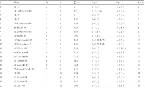
Table 3 describes some filters chosen with different design
types, number of feedback coefficientsN, number of
for-ward coefficientsM, input range, and word length. One
can notice that columnBitsindicates the word-length for
the integer and fractional parts of fixed-point represen-tations, including the sign. Besides, the word-length for fixed-point representations is estimated based on both
the |hk| summation and the input range, in order to
obtain optimized filters, in terms of reduced number of
bits. The columnBound shows the number of
consecu-tive entries applied to the filter (filter function unwinding), which is empirically determined to find violations of the associated property, up to given bound. Indeed, for each applied entry, the filter function is executed, in order to compute output samples. From the verification perspec-tive, all important information about the digital filters benchmarks are described in Table 3.
In Table 3, filters from 1 to 11 are verified in three dif-ferent realizations: Direct Form I (DFI), Direct Form II (DFII), and Transposed Direct Form II (TDFII), in order to investigate how filter structures can interfere in the occur-rence of some failures. Many of the selected test cases use second order structures, because such a realization is widely used and can be applied as a building block to form higher-order systems, as referred in “Fixed-point filters realization” Section.
Regarding the error verification experiments, they were fair enough to define a range larger than the quantization error interval, as given by (11). Due to that, an acceptable margin of two times the precision was fixed, that is, from
−2−l+1to 2−l+1. Note that all filter operations are
repre-sented in our verification engine as fixed-point arithmetic. The error verification only checks whether the output of a filter, implemented with reduced-word-length fixed-point representation, is within certain bounds, when compared to a double-precision reference output.
When evaluating time constraints, restrictions related to a 16 MHz processor, operating on a system with sample rate equal to 48 KHz, were considered. Such a rate was adopted due to its use as a standard audio sampling rate, commonly employed in professional equipment. One can notice that the system sample rate does not interfere in overflow and limit cycle conditions, because this is just a consequence of the fixed-point arithmetic.
Table 3Tested digital filters
# Filter N M |hk| Input Bits Bound
1 LP-IIR 2 1 2 [−1, 1] <2, 4> 6
2 LP-Butterworth-IIR 3 3 1.2 [−1.6, 1.6] <2, 5> 6
3 LP-IIR 3 1 4 [−1, 1] <3, 4> 6
4 LP-IIR 3 1 1.56 [−1, 1] <2, 4> 6
5 HP-ChebyshevI-IIR 3 3 1.33 [−1, 1] <2, 6> 6
6 BP-Elliptic-IIR 3 3 1.24 [−1, 1] <2, 8> 6
7 BS-Butterworth-IIR 3 3 1.81 [−1.1, 1.1] <2, 8> 6
8 BP-Elliptic-IIR 5 5 0.91 [−1.1, 1.1] <1, 7> 10
9 HP-Butterworth-IIR 5 5 1.58 [−1.27, 1.27] <2, 6> 10
10 BP-ChebyshevI-IIR 5 5 1.51 [−1.33, 1.33] <2, 6> 10
11 HP-Elliptic-IIR 7 7 5.39 [−1, 1] <3, 11> 14
12 HP-Cascade-IIR 6 6 12.4 [−1, 1] <5, 5> 14
13 BS-Cascade-IIR 9 9 2.45 [−1, 1] <3, 5> 19
14 LP-Parallel-IIR 6 6 16.6 [−1, 1] <5, 5> 13
15 LP-Cascade-IIR 6 6 7.64 [−1, 1] <4, 4> 13
16 Multiband-Parallel-IIR 9 9 2.75 [−1, 1] <4, 4> 19
17 LP-FIR 1 31 1.94 [−1, 1] <2, 6> 31
18 Multiband-FIR 1 9 2.18 [−1, 1] <2, 6> 13
19 Multiband-FIR 1 25 1.47 [−1, 1] <2, 8> 25
20 LP-WiFi-FIR 1 21 2.92 [−1, 1] <3, 5> 21
FIR filters are completely immune to limit cycles [2] (there is no feedback), and overflows can be prevented by applying a conservative criterion based on the filter-impulse-response absolute sum, in order to determine the word length. Indeed, FIR systems, checked for those prop-erties, finished successfully or timed out without finding a single counterexample. It is worth noticing that over-flow checking for intermediate operations was enabled, in order to guide a possible use of saturation arithmetic. As a result, the number of VCs are substantially increased, since it depends on the filter function unwinding bound.
For instance, if the unwinding bound is set tok, then the
verification engine produceskVCs to check for overflows,
which are harder to be checked by an SMT (or SAT) solver.
Here, DSVerifier6was employed and configured to use
the SMT solver Z3 v4.0 [57], with the bit-vector arith-metic enabled. Cox et al. [20, 21] observed that integer arithmetic is identical to that of bit-vector, in terms of pre-cision; however, there were tradeoffs in performance with (slight) advantage to bit-vector arithmetic.
For each benchmark, the verification engine was invoked by manually setting file name, timeout, and
bit-vector-arithmetic solver7. Note that array bounds,
pointer safety, and division by zero assertions are dis-abled, since the present work is focused on checking finite word-length problems, as previously described in
“Research design and methodology” Section. The above ESBMC call is thus used for checking safety properties
related to arithmetic under and overflow, when<file>
refers, for instance, toverify_overflow.c. In order to check
for limit cycle, timing constraints, and quantization error, the following files can be referenced by the above ESBMC
call, respectively: verify_limitcycle.c, verify_timing.c, and
verify_error.c. Each file contains the necessary filter calls and assertions used for property verification.
All experiments were conducted on an otherwise idle
Intel Core i7−2600, with a clock of 3.40 GHz and 24 GB
of RAM, running Fedora 64-bits. For all digital filters, the individual time limit has been set to 3600 s, except for cas-cade/parallel systems and FIR filters, in which the timeout is 7200 s. The presented elapsed times were measured
using thetimecommand.
General results
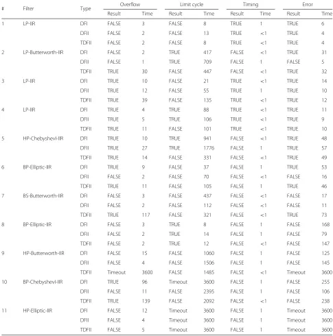
The parameters related to the chosen digital filters are used as inputs to the C filter-model. Tables 4, 5 and 6 summarize the results obtained with DSVerifier, by
pre-senting them asTRUEorFALSE, i.e., whether the
verifi-cation has finished successfully or not, respectively. The verification time is also shown for each type of failure assertion, and, when a particular verification exceeds the
Table 4Summary of results for the tested IIR filters
# Filter Type Overflow Limit cycle Timing Error
Result Time Result Time Result Time Result Time
1 LP-IIR DFI FALSE 3 FALSE 8 TRUE 1 TRUE 6
DFII FALSE 2 FALSE 13 TRUE <1 TRUE 4
TDFII FALSE 2 FALSE 8 TRUE <1 TRUE 4
2 LP-Butterworth-IIR DFI FALSE 2 TRUE 417 FALSE <1 TRUE 31
DFII FALSE 1 TRUE 709 FALSE 1 FALSE 5
TDFII TRUE 30 FALSE 447 FALSE <1 TRUE 32
3 LP-IIR DFI TRUE 10 FALSE 21 TRUE <1 TRUE 14
DFII TRUE 12 FALSE 55 TRUE 1 TRUE 10
TDFII TRUE 39 FALSE 135 TRUE <1 TRUE 12
4 LP-IIR DFI TRUE 4 TRUE 88 TRUE <1 TRUE 11
DFII TRUE 5 TRUE 106 TRUE <1 TRUE 9
TDFII TRUE 11 FALSE 101 TRUE <1 TRUE 10
5 HP-ChebyshevI-IIR DFI TRUE 10 TRUE 941 FALSE <1 TRUE 48
DFII TRUE 27 TRUE 1776 FALSE 1 TRUE 57
TDFII TRUE 14 FALSE 331 FALSE <1 TRUE 49
6 BP-Elliptic-IIR DFI TRUE 9 FALSE 37 FALSE 1 TRUE 53
DFII FALSE 2 FALSE 70 FALSE <1 FALSE 16
TDFII TRUE 11 FALSE 105 FALSE 1 TRUE 46
7 BS-Butterworth-IIR DFI FALSE 3 FALSE 437 FALSE <1 FALSE 17
DFII FALSE 2 FALSE 112 FALSE <1 FALSE 11
TDFII TRUE 117 FALSE 321 FALSE <1 TRUE 73
8 BP-Elliptic-IIR DFI FALSE 3 TRUE 8 FALSE 1 FALSE 168
DFII FALSE 2 TRUE 14 FALSE 1 FALSE 79
TDFII FALSE 2 TRUE 12 FALSE <1 FALSE 147
9 HP-Butterworth-IIR DFI FALSE 15 FALSE 1060 FALSE 1 FALSE 125
DFII FALSE 4 FALSE 1506 FALSE 1 FALSE 145
TDFII Timeout 3600 FALSE 1485 FALSE <1 Timeout 3600
10 BP-ChebyshevI-IIR DFI TRUE 96 Timeout 3600 FALSE 1 FALSE 255
DFII FALSE 11 FALSE 2395 FALSE 1 FALSE 106
TDFII TRUE 139 FALSE 2092 FALSE <1 FALSE 238
11 HP-Elliptic-IIR DFI FALSE 12 Timeout 3600 FALSE 1 Timeout 3600
DFII FALSE 4 Timeout 3600 FALSE 1 Timeout 3600
TDFII FALSE 5 Timeout 3600 FALSE 1 Timeout 3600
Table 5Summary of results for the tested cascade and parallel filters
# Filter Type Overflow Limit cycle Timing Error
Result Time Result Time Result Time Result Time
12 HP-Cascade-IIR TDFII Timeout 7200 Timeout 7200 FALSE 2 FALSE 1584
13 BS-Cascade-IIR DFII FALSE 259 Timeout 7200 FALSE 7 Timeout 7200
14 LP-Parallel-IIR DFII TRUE 911 FALSE 3656 FALSE 3 Timeout 7200
15 LP-Cascade-IIR DFII FALSE 261 FALSE 4059 FALSE 3 FALSE 189
Table 6Summary of results for the tested FIR filters
# Filter Type Timing Error
Result Time Result Time
17 LP-FIR DFI FALSE 1 Timeout 7200
18 Multiband-FIR DFI FALSE 1 TRUE 7915
19 Multiband-FIR DFI FALSE 1 Timeout 7200
20 LP-WiFi-FIR DFI FALSE 1 Timeout 7200
One can notice that the proposed system is able to detect failures in various digital filter types, which are implemented with different structures, orders, or fixed-point formats. However, the verification time tends to be higher for high-order filters and long word-length for-mats, since those lead to harder VCs. In particular, the verification time tends to be higher when checking over-flows, in filters that contain a high number of forward and feedback coefficients, as can be seen from test case 9 onward. In addition, timeout events occurred when checking for limit cycles, with digital filters that present long word-length for the fractional part representation (e.g., test case 11). The error verification also leads to high verification times, since it needs to calculate the output twice, that is, for fixed- and floating-point arithmetic for-mats. Apart from that, time constraints are easily verified, since this procedure consists of only checking the time response of a sequential piece of code.
Another important observation regarding verification times, as noted during tests conducted for validating the proposed methodology, is that failing test cases tend to be quickly checked. The main reason is that the model-checking algorithm stops a verification procedure when-ever it finds a counterexample; howwhen-ever, cases where no defect is found tend to have high verification times, or even produce a timeout. In such scenarios, a wide set of non-deterministic inputs is applied, which generates veri-fication conditions that are hard to be checked and makes this procedure very time-consuming. That can be noticed, for instance, on the limit cycle verification procedure for test cases 9, 10, and 11, and also in test case 9, during the overflow check. In the error verification of test case 9, the result indicates a failure for Direct Form I and Direct Form II implementations, in less or equal to 15 s; for the Trans-posed Direct Form II, the verification gets a time-out, without finding an error beyond the fixed limits. It indi-cates that it is hard to find an input that produces a high error value for this particular structure, which suggests that such a realization may properly operate most of the time; however, it cannot be guaranteed, since the model checking did not finish.
The timing verification reported failures for all cases with order higher than 2, which present more than 3 for-ward or feedback coefficients. Actually, considering the modeled structures implemented in C, only filters 1, 3, and
4 meet the time constraint requirements, when running on the specified platform.
Filter-structure considerations
Although different filter structures lead to the same final filters, as long as the same coefficients are used, the internal computation procedures are completely different. It can be seen, especially in overflow and limit cycle ver-ifications, that a filter may fail or pass according to its implementation structure. That occurs due to the order of intermediate operations, which changes from one struc-ture to another. The timing constraint verification is also affected by the filter structure, since the number of addi-tions and multiplicaaddi-tions are different in each form. For instance, test case 4 should not be implemented using the Transposed Direct Form II, in order to avoid limit-cycle occurrences. Regarding test cases 6 and 7; however, there is no viable option, unless the designer uses some tech-nique (see Section “Finite word-length effects in digital filters”), in order to prevent limit cycles.
For instance, in test case 2, the verification detects over-flow failures for the Direct Form I and Direct Form II structures, in addition to a limit cycle failure for the Transposed Direct Form II structure; the remaining prop-erties finished successfully. On this particular case, the designer intending to implement this filter, in Direct Form I or II, would need to use an accumulator with a higher number of bits for the integer part, two’s complement arithmetic, or other technique, when saturation arith-metic is employed, for preventing overflow. When using the Transposed Direct Form II, the designer could mod-ify the overflow mode of the system, in order to perform saturation arithmetic for solving limit cycle oscillations. The techniques to prevent overflow and limit cycle, as referred by Proakis et al. in [2], generally increase noise levels. As a result, after performing such modifications, the designer should necessarily run the verification engine another time, in order to ensure that the output error is within an acceptable margin.
FIR filter results
The results collected from the FIR filter experiments are described in Table 6. The high-order systems cause long verification times, due to the search for a counterexample that produces a high-output error. The timing verifica-tions are also quickly performed, as in the other presented cases. Multiband filters 18 and 19 were also verified for these properties and, as can be seen in test case 19, the timing failure indicates that the particular implementation must be simplified.
Final considerations
Figure 10 shows a summary of all obtained results, clas-sified by verification category. Figure 10a presents results regarding arithmetic under- and overflows, which show that DSVerifier was able to find property violations in 50 % of the benchmarks. In addition, only 8 % of the cases timed out, due to the high number of generated VCs, regarding the system under verification. In particular, a VC is generated for each arithmetic expression of the dig-ital filter implementation, considering non-deterministic inputs.
Figure 10b presents results regarding limit cycle verifi-cation. In summary, DSVerifier was able to find property violations in 60 % of the benchmarks and timed out in 16 % of the them, given that limit cycle verifications of high-order filters, with long word lengths, led to a large state-space to be explored by the chosen SMT solver. One can notice that the results of both categories do not include verification of FIR filters, due to the already stated reasons.
Figure 10c presents results regarding timing-constraint verifications, which show that DSVerifier was able to find timing violations in 79 % of the benchmarks. The ver-ification of timing constraints is fast (in some cases, it takes less than 1 s), and no benchmark, in this category, timed out.
Finally, Fig. 10d presents results regarding quantiza-tion errors, where DSVerifier was able to find property violations in 33 % of the benchmarks and timed out in 24 % of them, for reasons previously stated for overflow verification.
In summary, the presented results show that the pro-posed verification methodology covers a large set of checks, which are required by common designs, in order to define the fixed-point representation format. Besides, it is also useful in determining the filter structure for system realization, i.e., in observing whether the system implementation is feasible, given the project constraints.
It has also been shown that DSVerifier can be a very effective tool for verifying digital filters, aiding DSP engineers to automatically discover low-level properties violations, which are hard to found by traditional sim-ulation tools (e.g., MATLAB [65]), since they depend on a set of input stimuli, in order to improve the state space coverage, and require a significant manual inter-vention from designers. In particular, simulations tools [17, 66] might neglect some failures, due to low cov-erage achieved during simulations (covcov-erage problem) [20, 21]. Our verification methodology then replaces typical validation processes currently used by DSP engineers.