This item was submitted to Loughborough’s Institutional Repository (https://dspace.lboro.ac.uk/) by the author and is made available under the
following Creative Commons Licence conditions.
For the full text of this licence, please go to: http://creativecommons.org/licenses/by-nc-nd/2.5/
Modelling and Real-Time Control of a High
Performance Rotary Wood Planing Machine
By
Philips S. Ogun
A doctoral thesis submitted in partial fulfilment of the requirements
for the award of Doctor of Philosophy of Loughborough University
July 2012
ii
Abstract
_________________________________________________________________________ Rotary planing is one of the most valuable machining operations in the timber processing industry. It has been established that cutting tool inaccuracy and forced vibration during the machining process are the primary causes of surface quality degradation. The main aim of this thesis is to design a control architecture that is suitable for adaptive operation of a wood planing machining in order to improve the quality of its surface finish.
In order to achieve the stated goal, thorough understanding of the effects of machine deficiencies on surface finish quality is required. Therefore, a generic simulation model for synthesising the surface profiles produced by wood planing process is first developed. The model is used to simulate the combined effects of machining parameters, vibration and cutting tool inaccuracy on the resultant surface profiles.
It has been postulated that online monitoring of surface finish quality can be used to provide feedback information for a secondary control loop for the machining process, which will lead to the production of consistently high quality surface finishes. There is an existing vision-based wood surface profile measurement technique, but the application of the technique has been limited to static wood samples. This thesis extends the application of the technique to moving wood samples. It is shown experimentally that the method is suitable for in-process surface profile measurements.
The current industrial wood planing machines do not have the capability of measuring and adjusting process parameters in real-time. Therefore, knowledge of the causes of surface finish degradation would enable the operators to optimise the mechanical structure of the machines offline. For this reason, two novel approaches for characterising defects on planed timber surfaces have been created in this thesis using synthetic data. The output of this work is a software tool that can assist machine operators in inferring the causes of defects based on the waviness components of the workpiece surface finish.
The main achievement in this research is the design of a new active wood planing technique that combines real-time cutter path optimisation (cutting tool inaccuracy compensation) with vibration disturbance rejection. The technique is based on real-time vertical displacements of the machine spindle. Simulation and experimental results obtained from a smart wood planing machine show significant improvements in the dynamic performance of the machine and the produced surface finish quality.
Potential areas for future research include application of the defects characterisation techniques to real data and full integration of the dynamic surface profile measurements with the smart wood planing machine.
iii
Acknowledgements
_________________________________________________________________________
I give glory to the Almighty God for his grace and protection over my life throughout the period of this research.
I owe my deepest gratitude to Loughborough University and the EPSRC Innovative Manufacturing and Construction Research Centre for awarding me a scholarship.
I am thankful to my supervisors, Professor Mike Jackson and Professor Rob Parkin for their encouragements, guidance and supports. Your feedbacks during our several meetings helped me to develop more confidence in myself and also gain broader knowledge of the subject area. I will also like to thank the technical and administrative staff of the Wolfson School of Mechanical and Manufacturing Engineering for their help.
I do appreciate my friends and colleagues at the Intelligent Automation Research Centre for their contributions, especially Mathavan, Matt, Tuss and Luk.
I am very much indebted to all my family members for their prayers. I thank my father, Mr Pascal Ogun for his love. To my uncle and his wife, Mr and Mrs Thomas M. Ogun, I say a big thank you for your kindness and generosity towards me. My God will reward you.
How can I forget the ladies in my life? I say a big thank you to my wife, Bukola (olo emi). It would have been much more difficult without your help, understanding, cooperation, love and care. Nido my daughter, we can now visit the parks and all the beautiful places.
iv
This thesis is dedicated to my late mother. She
was not formally educated but she would
definitely be proud of my achievement.
v
Table of Contents
_________________________________________________________________________ Abstract ... ii Acknowledgements ... iii Table of Contents ... v List of Figures ... x List of Tables ... xv Notations ... xvii Glossary of Terms ... xx 1 Introduction ... 1 1.1 Project Background ... 11.2 Research Aim and Objectives ... 5
1.3 Project Work Breakdown Structure ... 6
1.4 Existing Facilities for the Project ... 8
1.5 Research Scope and Methodology ... 10
1.6 Proposed Control Architecture ... 10
1.7 Overview ... 13
2 Literature Review ... 17
2.1 Rotary Wood Planing – A Brief Review ... 18
2.1.1 Surface Waviness Quality ... 18
2.2 Waviness Simulation Algorithms ... 19
2.3 Surface Quality Improvements ... 22
2.4 Real-time Optimisation of Process Kinematics ... 23
2.5 Vibration Control ... 26
2.5.1 Passive Vibration Control Method ... 28
2.5.2 Active Vibration Control ... 30
vi
2.6 Surface Quality Assessments ... 39
2.7 Signal and Data Processing Techniques ... 45
2.8 Adaptive Control ... 49
2.9 Intelligent Control ... 54
3 Simulation Model for the Rotary Wood Planing Process ... 58
3.1 Justification for the New Algorithm ... 58
3.2 Description of the Algorithm ... 60
3.3 Generalised Model for the Circular Arc Theory ... 63
3.4 Model for the Extended Circular Arc Theory ... 68
3.4.1 Cutting Tool Kinematics Modelling ... 68
3.4.2 Cutterhead Vibration Modelling ... 70
3.4.3 Cutterhead Inaccuracy Modelling ... 73
3.5 Extraction of the Surface Profile ... 76
3.6 Depth of Cut Consideration ... 81
3.7 Simulation Examples ... 82
3.8 Summary and Conclusions ... 90
4 Dynamic Wood Surface Profile Measurements ... 91
4.1 Background ... 91
4.2 Theory of Photometric Stereo and Shape from Shading ... 93
4.2.1 Surface Albedo Recovery using PS ... 94
4.2.2 Surface Gradients Recovery using PS ... 95
4.2.3 Surface Gradients Recovery using SFS ... 98
4.2.4 Height Recovery from the Surface Gradients ... 99
4.3 Camera Calibration ... 99
4.4 Determination of the Optimum Light Source Positions ... 101
4.5 Recovery of Wood Surface Reflectance Properties (Albedo) ... 103
vii
4.6.1 Test Rig Setup ... 109
4.6.2 Challenges with the DPS ... 110
4.7 Experimental Results ... 112
4.8 Summary and Conclusions ... 115
5 Characterisation of Defects on Planed Timber Surfaces ... 117
5.1 Introduction ... 117
5.2 Empirical Mode Decomposition ... 119
5.2.1 Physical Significance of the IMFs ... 123
5.2.2 Apriori Knowledge Requirements ... 128
5.3 Comparisons between EMD and Fourier Analysis ... 129
5.4 Principal Component Analysis Method ... 132
5.4.1 Procedure for Applying PCA ... 133
5.4.2 Significance of the Principal Components ... 135
5.4.3 Classification of the Principal Components ... 144
5.5 Considerations for Practical Applications ... 147
5.6 Summary and Conclusions ... 149
6 Test Rig Characterisation and System Identification ... 151
6.1 Sensors and Actuators Arrangement ... 151
6.2 Spindle Support Operation ... 156
6.3 Characteristics of the Piezoelectric Actuators ... 158
6.4 Feed and Cutting Motors Tests ... 161
6.5 Plant Modelling ... 164
6.5.1 Background ... 164
6.5.2 System Identification and Parameter Estimation ... 167
6.5.3 Input-Output Data Collection ... 169
6.5.4 Model Parameters Estimation and Validation ... 175
viii
7 Optimal Controller Design for the Active Machining System ... 180
7.1 Principles of the Cutter Run out Compensation ... 180
7.2 Structure of the Proposed Control System ... 184
7.3 The Optimal Control Problem ... 187
7.3.1 Optimal Tracking Controller Design ... 188
7.3.2 Optimal Observer Design (Kalman Filter) ... 191
7.3.3 Optimal Linear Quadratic Gaussian (LQG) Compensator Design ... 192
7.4 Vibration Disturbance Feedforward Compensation ... 196
7.5 Simulation and Rapid Control Prototyping ... 201
7.5.1 Control System Simulation ... 201
7.5.2 Real-Time Testing Environment ... 204
7.5.3 Real-Time Controller Performance Test ... 205
7.6 Knowledge-Based Adaptive Control Strategy ... 213
7.7 Summary and Conclusions ... 217
8 Experimental Results and Discussions ... 218
8.1 Planer Rig Closed-loop Performance Tests – Engineering Tests ... 218
8.2 Influence of cutterhead displacement on the surface form ... 228
8.3 Wood Machining Experiments - Two-Knife Tests ... 229
8.4 Wood Machining Experiments - Four-Knife Tests ... 233
9 Conclusions and Recommendations ... 242
9.1 Conclusions ... 242
9.2 Recommendations for Further Work ... 245
References ... 247
Appendix A Camera Calibration ... 257
Appendix B Test Rig State-Space Model ... 259
Appendix C Simulink Models for the Tracking Controller ... 260
ix Appendix E Machine Vision Test Rig Components ... 264 Appendix F Alicona InfiniteFocus Instrument ... 271 Appendix G Publications ... 272
x
List of Figures
_________________________________________________________________________
Figure 1.1 Principles of the rotary machining process ... 2
Figure 1.2 Sharp and jointed cutters (Elmas, 2008) ... 4
Figure 1.3 Project work breakdown structure ... 7
Figure 1.4 The small-scale wood planing machine ... 8
Figure 1.5 The vision-based wood surface measurement system ... 9
Figure 1.6 Proposed knowledge-based adaptive control architecture ... 12
Figure 2.1 Non-defective and defective wood surfaces ... 19
Figure 2.2 Circular arc approximation method ... 20
Figure 2.3 Surface quality improvement techniques ... 23
Figure 2.4 Cutterhead advance detail (Brown et al., 2002) ... 24
Figure 2.5 Cutterhead retract detail (Brown et al., 2002) ... 25
Figure 2.6 Modification of rotary machining process (Hynek, 2004) ... 25
Figure 2.7 A structure with three vibration control methods: (a) passive, (b) active, and (c) semi-active configuration (Jalili, 2002) ... 28
Figure 2.8 Hardware setup for the chatter control test rig (Dohner et al., 2004) ... 33
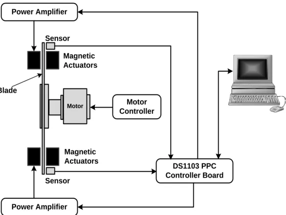
Figure 2.9 Structure of saw blade vibration control test rig (Chen et al., 2003) ... 35
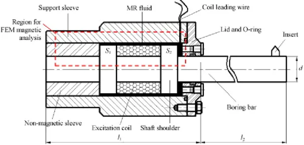
Figure 2.10 Structure of the MR fluid-controlled boring bar (Mei et al., 2009) ... 37
Figure 2.11 Components of the stylus measurement system... 41
Figure 2.12 Image acquisition sequence for the photometric stereo technique ... 42
Figure 2.13 Gain scheduling adaptive control diagram (Karray and De Silva, 2004) .. 50
Figure 2.14 Model reference adaptive control diagram (Karray and De Silva, 2004) .. 51
Figure 2.15 Model identification adaptive control diagram (Karray and De Silva, 2004) 52 Figure 2.16 Structure of the internal model control ... 56
Figure 3.1 Idealised and the actual surface waviness (Hynek, 2004) ... 61
Figure 3.2 Fundamental principles of the surface waviness modelling (Jackson, 1986) 63 Figure 3.3 Assumed movements of the workpiece in circular arc theory model ... 67
Figure 3.4 Assumed cutterhead vibration in circular arc theory model ... 67
Figure 3.5 Instantaneous positions of the knife tip ... 70
xi
Figure 3.7 Effects of coarse sampling of the cutterhead movement ... 77
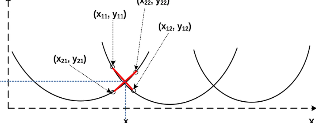
Figure 3.8 Calculating the point of intersection between two adjacent curves ... 79
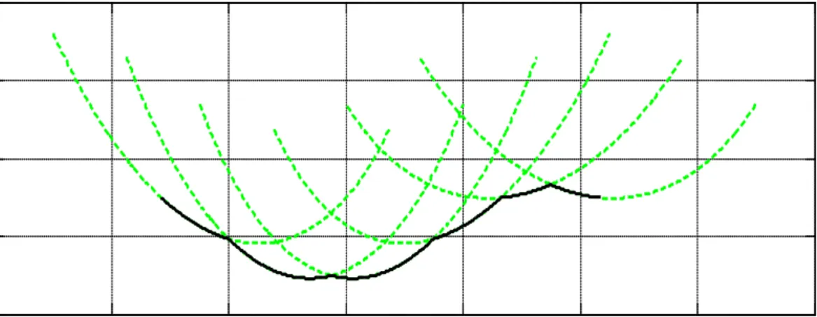
Figure 3.9 Knife tip paths and the extracted surface profile ... 80
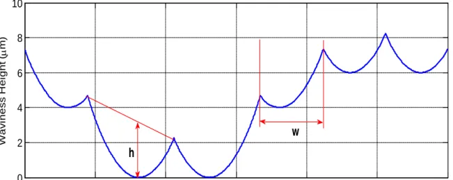
Figure 3.10 Extraction of cuttermarks height and width ... 81
Figure 3.11 Depth of cut consideration ... 81
Figure 3.12 Effect of small depth of cut ... 82
Figure 3.13 Six-knife finish without any defect ... 83
Figure 3.14 The effect of proud knives ... 85
Figure 3.15 Initial cutting conditions of the cutterhead ... 86
Figure 3.16 The effect of once per revolution vibration on two-knife finish ... 87
Figure 3.17 The effect of once per revolution vibration on four-knife finish ... 88
Figure 3.18 The effect of vibration and proud knives on six-knife finish ... 89
Figure 4.1 Geometry of the generalised Lambertian surface photometric function ... 93
Figure 4.2 Schematic of the 2-image photometric stereo setup ... 97
Figure 4.3 Conversion from 3D to 2D profile by column-wise averaging (Yang, 2006) 98 Figure 4.4 Images of wood obtained from different lightening directions ... 103
Figure 4.5 Beech sample captured with light source at azimuth angle of 00 ... 104
Figure 4.6 Beech sample captured with light source at azimuth angle of 1500 ... 104
Figure 4.7 Beech sample captured with light source at azimuth angle of 1800 ... 104
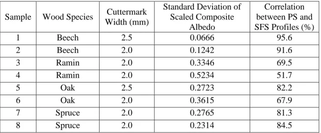
Figure 4.8 PS and SFS profiles of a Beech sample with 2.5mm cuttermarks ... 106
Figure 4.9 PS and SFS profiles of a Spruce sample with 2mm cuttermarks ... 107
Figure 4.10 Interconnections between the components of the machine vision test rig110 Figure 4.11 Skewed cuttermarks due to the rolling shutter effect ... 111
Figure 4.12 Static PS profile vs. Dynamic PS profile for Beech sample ... 112
Figure 4.13 Static PS profile vs. Dynamic PS profile for Oak sample ... 113
Figure 4.14 Perfectly matched and 8 pixels mismatched surface profiles ... 114
Figure 4.15 Perfectly matched and 15 pixels mismatched surface profiles ... 115
Figure 5.1 The data with the upper and lower envelopes ... 121
Figure 5.2 The data with the mean of the upper and lower envelopes ... 121
Figure 5.3 The difference between the data and the mean of the envelopes ... 121
Figure 5.4 Case 1: (a) The original surface profile; (b) The first intrinsic mode function; (c) The second intrinsic mode function ... 124
xii Figure 5.5 Case 2: (a) The original surface profile; (b) The first intrinsic mode function;
(c) The second intrinsic mode function ... 125
Figure 5.6 Case 3: (a) The original surface profile; (b) The first intrinsic mode function; (c) The second intrinsic mode function ... 126
Figure 5.7 Case 4: (a) The original surface profile; (b) The first intrinsic mode function; (c) The second intrinsic mode function ... 128
Figure 5.8 Waviness defect produced by extreme values of the vibration amplitude .. 130
Figure 5.9 Defects caused by varying imbalance mass positions ... 131
Figure 5.10 Vibration recovered from profiles with varying imbalance mass positions 132 Figure 5.11 Four-knife finish with once per revolution vibration defect ... 136
Figure 5.12 Four-knife finish with once per revolution vibration defect (ψ = π/2) .... 137
Figure 5.13 Four-knife finish with once per revolution vibration defect (ψ = π/4) .... 137
Figure 5.14 Four-knife finish with once per revolution vibration defect (ψ = π/6) .... 137
Figure 5.15 Four-knife finish with once per revolution vibration defect (ψ = π/8) .... 138
Figure 5.16 Four-knife finish with twice per revolution vibration defect ... 139
Figure 5.17 Four-knife finish with once per two revolutions vibration defect ... 140
Figure 5.18 Six-knife finish with once per revolution vibration defect ... 141
Figure 5.19 Six-knife finish with twice per revolution vibration defect (ψ = 0) ... 142
Figure 5.20 Six-knife finish with twice per revolution vibration defect (ψ = π /10) ... 142
Figure 5.21 The upper, lower and average envelops of a surface profile ... 144
Figure 5.22 Structure of the competitive neural network ... 145
Figure 5.23 The simulated noisy surface profile ... 147
Figure 5.24 The original and the filtered surface profiles ... 149
Figure 6.1 Actuators and sensors arrangement on the smart spindle unit ... 152
Figure 6.2 Geometry of the spindle unit ... 153
Figure 6.3 Experimental setup for the spindle displacement measurements ... 155
Figure 6.4 Mechanical supports for the spindle ... 156
Figure 6.5 Vibration of the spindle rotating at 3000rpm ... 157
Figure 6.6 The hysteresis curves for piezoelectric actuator B ... 160
Figure 6.7 The hysteresis curves for piezoelectric actuator D ... 160
Figure 6.8 Spindle responses to step voltage inputs ... 162
Figure 6.9 Speed-time graph of the feed motor ... 163
xiii
Figure 6.11 Time-domain response: spindle with cutterhead of mass 106g ... 172
Figure 6.12 Time-domain response: spindle with cutterhead of mass 190g ... 173
Figure 6.13 Time-domain response: spindle with cutterhead of mass 293g ... 173
Figure 6.14 Frequency response function: spindle with cutterhead of mass 293g ... 175
Figure 6.15 Measured and predicted outputs for second order model ... 176
Figure 6.16 Measured and predicted outputs for fourth order model ... 177
Figure 6.17 Measured and predicted outputs for sixth order model ... 177
Figure 7.1 Principle of the cutterhead inaccuracy compensation ... 181
Figure 7.2 Relationship between pulse width and cutting speed ... 183
Figure 7.3 Control system with both feedforward and feedback control ... 186
Figure 7.4 Structure of the LQG tracking controller with integral action ... 193
Figure 7.5 Cutterhead and the attached imbalance mass of 116g ... 197
Figure 7.6 Spindle vibrations against angular positions of the spindle ... 198
Figure 7.7 Real-time measured and generated spindle vibrations ... 199
Figure 7.8 Tracking response obtained without integral action ... 202
Figure 7.9 Tracking response obtained with integral action ... 202
Figure 7.10 Tracking response for the plant with unknown vibration disturbance ... 203
Figure 7.11 Tracking response for the plant with feedforward vibration compensation 204 Figure 7.12 Schematic of the active wood machining control environment ... 205
Figure 7.13 Tracking response of the spindle (2-knife cutterhead rotating at 2000rpm) 207 Figure 7.14 Tracking response of the spindle (4-knife cutterhead rotating at 1000rpm) 208 Figure 7.15 Tracking response of the spindle (4-knife cutterhead rotating at 3000rpm) 208 Figure 7.16 Comparison between uncontrolled and feedback-controlled vibration ... 210
Figure 7.17 Comparison between uncontrolled and hybrid-controlled vibration ... 210
Figure 7.18 Tracking response obtained without vibration compensation ... 212
Figure 7.19 Tracking response obtained with hybrid vibration compensation ... 213
Figure 7.20 The integrated active wood machining system ... 216
Figure 8.1 Trapezoidal pulse ... 219
Figure 8.2 Tracking response of the spindle rotating at 2000rpm ... 220
xiv
Figure 8.4 Tracking response of the spindle rotating at 4000rpm ... 221
Figure 8.5 Tracking response of the spindle rotating at 5000rpm ... 221
Figure 8.6 Controlled and uncontrolled vibration of the spindle rotating at 1000rpm . 223 Figure 8.7 Controlled and uncontrolled vibration of the spindle rotating at 2000rpm . 223 Figure 8.8 Controlled and uncontrolled vibration of the spindle rotating at 3000rpm . 224 Figure 8.9 Controlled and uncontrolled vibration of the spindle rotating at 4000rpm . 224 Figure 8.10 Tracking response of the spindle with imbalance mass at 1000rpm ... 226
Figure 8.11 Tracking response of the spindle with imbalance mass at 2000rpm ... 226
Figure 8.12 Tracking response of the spindle with imbalance mass at 3000rpm ... 227
Figure 8.13 Tracking response of the spindle with imbalance mass at 4000rpm ... 227
Figure 8.14 Two-knife test machined without compensation (Experiment 1) ... 231
Figure 8.15 Two-knife test machined with compensation (Experiment 1) ... 231
Figure 8.16 Two-knife test machined without compensation (Experiment 2) ... 232
Figure 8.17 Two-knife test machined with compensation (Experiment 2) ... 233
Figure 8.18 Four-knife test machined without compensation ... 234
Figure 8.19 Four-knife test machined with 14µm downward displacement of cutter one 235 Figure 8.20 Four-knife test machined with 14µm downward displacement of cutter two 235 Figure 8.21 Four-knife test machined with 14µm downward displacement of cutter three 236 Figure 8.22 Four-knife test machined with 14µm downward displacement of cutter four 236 Figure 8.23 Four-knife test machined with compensation at 1000rpm ... 237
Figure 8.24 Four-knife test machined with compensation at 4000rpm ... 238
Figure 8.25 Four-knife finish with cutterhead inaccuracy and vibration defects ... 240 Figure 8.26 Four-knife finish with cutterhead inaccuracy and vibration compensation
xv
List of Tables
Table 3.1 Surface waviness assessment for example 1 ... 84
Table 3.2 Surface waviness assessment for example 2 ... 85
Table 3.3 Surface waviness assessment for example 3 ... 87
Table 3.4 Surface waviness assessment for example 4 ... 89
Table 3.5 Surface waviness assessment for example 5 ... 90
Table 4.1 Albedo uniformity for various wood samples ... 106
Table 4.2 Percentage correlation between static and dynamic surface profile measurements for some selected wood samples ... 113
Table 5.1 Machining Parameters for EMD ... 123
Table 5.2 Principal components for four-knife finish with once per revolution vibration 136 Table 5.3 Principal components for four-knife finish with once per revolution vibration at varying imbalance positions ... 138
Table 5.4 Principal components for four-knife finish with twice per revolution vibration 139 Table 5.5 Principal components for four-knife finish with once per two revolutions vibration 140 Table 5.6 Principal components for six-knife finish with once per revolution vibration 141 Table 5.7 Principal components for six-knife finish with twice per revolution vibration 142 Table 5.8 Principal components for ten-knife finish with once per revolution vibration 143 Table 5.9 Principal components for ten-knife finish with once per two revolutions vibration 143 Table 6.1 Spindle displacements measurement ... 154
Table 6.2 Spindle vibrations due to mass imbalance ... 157
Table 7.1 Machining parameters for control system simulation ... 201
Table 8.1 Reference spindle position specifications ... 219
Table 8.2 Controller efficiency for cutterhead inaccuracy compensation ... 222
xvi
Table 8.4 Theoretical and actual uncontrolled vibration amplitudes ... 225
Table 8.5 Controller efficiency for cutterhead inaccuracy and spindle vibration compensation ... 228
Table 8.6 Angular positions and static run outs of the two cutting knives ... 230
Table 8.7 Angular positions and static run outs of the four cutters ... 233
xvii
Notations
_________________________________________________________________________ a, b cutterhead centre point
ai, bi cutterhead centre position when the ith knife is engaged with the workpiece
a(t), b(t) instantaneous cutterhead centre point
bi(t) instantaneous cutterhead vertical displacement for the ith knife (mm)
ci(t) instantaneous cutterhead horizontal displacement for the ith knife (mm)
d cutterhead vibration amplitude (mm)
dpixel workpiece displacement in pixel
drev number of displacements per cutterhead revolution
dt distance moved by cutterhead (mm)
e radial position of resultant mass imbalance (mm) F imbalance force (N)
Gs piezoelectric actuator static gain (µm/V)
h cuttermark height (mm) ha cuttermark actual height (mm)
H peak-to-peak amplitude of a surface profile (mm)
i knife index
I image intensity matrix
Ii image intensity matrix for the ith frame
Io intensity of incident light
I(x, y) intensity of light reflected at local point (x, y) j cutterhead revolution index
k effective stiffness of actuators and spindle support (N/m) k1 coefficient of camera lens 2nd order radial distortion
xviii k2 coefficient of camera lens 4th order radial distortion
k3 coefficient of camera lens 6th order radial distortion
kp piezoelectric actuator stiffness (N/m)
ks flexural hinges support stiffness (N/m)
Kx state feedback gain
Ki steady state error integral gain
Kr reference signal feedforward gain
L Kalman filter gain matrix m resultant imbalance mass (kg) N number of cutting knives Nc number of cuttermarks
Np number of peaks in recovered vibration signal
p cuttermark pitch (mm)
p1, p2 coefficients of tangential distortion
p(x) Gradient of a surface at any local point in the x direction
R knife radius (mm)
Ri radius of ith knife (mm)
Rs radius of reference knife (mm)
Rmax maximum peak to valley height of a surface profile (mm) SR camera spatial resolution (pixel/mm)
x, y point on cutterhead circumference
xa, ya spindle displacements in the actuator coordinate system (mm)
xd, yd original location of distorted point
xo, yo image principal point
xix xs, ys spindle displacements measured in the sensor coordinate system(mm)
X spindle vibration amplitude (mm)
t time (s)
T period of cutterhead revolution (s) Tk knife-passing period (s)
vf feed speed (mm/s)
vc cutterhead linear speed (mm/s)
w cuttermark width (mm)
y(t) instantaneous vertical position of the spindle (mm)
α phase shift of cutterhead vibration after each revolution (rad) γ angle between two successive knives on a cutterhead (rad) λc filter cut-off wavelength (mm)
ω cutting speed (rev/s)
ωc cutterhead angular speed (rad/s)
ωosc frequency of cutterhead oscillation (rad/s)
φ angle between sensor axis and actuator axis (degree) ψ angular position of resultant mass imbalance (rad)
ρ surface albedo
τ light source azimuth or tilt angle (rad) θ cutterhead angular position (rad)
θa angular position of resultant imbalance mass (rad)
θi cutterhead angular position at the lowest point of the ith knife (rad)
θo initial cutterhead angular position (rad)
θ(t) instantaneous cutterhead angular position (rad) σ light source zenith or slant angle (rad)
xx
Glossary of Terms
_________________________________________________________________________ Albedo: A measure of the reflectivity of a surface. It is defined as the fraction of
incident light that is being reflected by the surface.
Chatter: Machining vibrations that occur due to the relative movement between the workpiece and the cutting tool
Cuttermarks: Waves produced on a rotary planed timber due to the kinematics of the machining process
Jointing: A term used to describe the dressing of cutting tools in rotary wood planing in order to true all the cutting edges to a common cutting circle
Kerf: The width of a groove made a cutting tool, such as a saw
Stability lobe: A tool used to predict and control vibration (chatter) during machining operations
1
1
Introduction
_________________________________________________________________________
1.1 Project Background
Machining of parts is central to almost every production and manufacturing process. Modern day machining processes are characterised by subtle material and process element variations, inaccurate tooling conditions, and process disturbances, such as vibration. These undesirable conditions are the main causes of reduced product quality. There is an ever increasing desire to produce components with very high surface integrity requirements. Such requirements have not always been met by existing machinery. There is the need for machines to have some level of awareness of these quality deteriorating conditions and also respond appropriately in order to nullify or minimise their effects.
Research and development interests in actively controlled machining have grown over the years within the academic and industrial communities but the main focus has been on metalworking operations. Nevertheless, wood machining has been an area of research within the Mechatronics Research Group at Loughborough University (MRGLU), where the research work reported in this thesis is being undertaken. A number of novel non-conventional machining techniques and surface profile measurement systems have been developed by previous researchers at the MRGLU. The purpose of the research reported in this thesis is to further improve on the existing ideas, investigate new approaches and finally integrate all the ideas in order to support the development of a high performance wood machining system.
2 The wood machining operations can be generally classified into orthogonal and peripheral processes. In the orthogonal process, the cutters are in a straight line and are perpendicular to the workpiece; while in the peripheral process, the cutters are located at the periphery of a rotating cutterhead. Most applications within the woodworking industry make use of the rotary machining operations. Rotary planing and moulding are by far the most valuable machining processes in the value-added woodworking industry (Ratnasingham, 2008).
The basic principle of the rotary machining process is such that wood chips are severed from an advancing workpiece by one or more cutting knives, which are clamped into the rotating cutterhead (Figure 1.1). The process is similar to the milling of metal. The primary differences are that the feed speed and the cutting speed in rotary wood planing far exceed those of metal milling. Wood planing is characterised by high cutting speed typically within the range of 30-80m/s, with corresponding high feed speeds ranging from 0.083-1.67m/s (Brown et al., 2002). In industrial planing machines, the cutting knives are usually between four and eight in number and can be as many as twenty for very high feed speed applications (Jackson, 1986). In contrast to the helical cutting edges used in metal milling, the cutting edges are mostly straight in rotary wood machining.
p h R f
v
ω CutterheadKnife Workpiece3 The surfaces produced by the planing process will first appear to have a flat topography when viewed from far away distance. However, on close and detailed examination of the surfaces, the majority of the machined surfaces exhibit some wave patterns (known as cuttermarks), which are orthogonal to the workpiece feed direction. The waves results from the intermittent engagement of the cutting knives with the timber.
The primary factors that influence the sizes of the cuttermarks are the machining parameters (number of cutting knives, the radius of the cutting knives, cutting speed and feed speed). These machining parameters are selected by the operators in order to produce the desired waviness pitch and height. However, it has been observed in practice that some conditions such as forced spindle vibration and cutting tool inaccuracy introduce significant surface finish defects. These defects manifest in form of inconsistency and non-uniformity of the cuttermarks. Although waviness defects can also be amplified by the type and condition of the wood being machined, they are generally a function of the machine deficiencies (Jackson, 1986; Sitkei and Magoss, 2003). The planing operation can produce various types of defective surfaces, which have been estimated to reduce the processing yield by almost 27% (Ratnasingham, 2008).
The cutting tool inaccuracy is caused by proud knives or eccentric running of the cutterhead relative to the machined timber surface. Traditional mechanical solution to the problem of cutterhead inaccuracy in the woodworking industry is to apply a process known as jointing. Jointing is the term used to describe cutting tool dressing at the spindle speed in order to true all the cutting edges to a common cutting circle (Jackson et. al, 2007). Without the jointing process, the uneven knives produce significant repeating patterns of non-uniform cuttermarks on the workpiece.
4 The disadvantage of the jointing process is that it introduces “joint lands” on the cutting knives thereby removing or decreasing any back clearance angle from the cutter (Figure 1.2). This accelerated tool wear does not only increase the tooling cost, it also increases the normal cutting forces generated during the machining process, and hence increase in power consumption (Jackson et. al, 2007). The jointing can also cause significant variation in cutting forces due to joint land variation from one cutting knife to the other. The resulting cutting force variation will lead to surface defects depending on its severity. In some cases, the jointing device could also modify the cutting tool tracking orbit due to jointer vibration excited by cutterhead imbalance (Jackson et al., 2007). It is noted that this current method used in the woodworking industry to achieve good quality surface finish has disadvantages that defeat its original attractiveness.
Sharp knife
Jointed knife
Joint land Figure 1.2 Sharp and jointed cutters (Elmas, 2008)
Apart from the cutterhead inaccuracy, structural vibration is another major cause of defects in rotary wood machining. Vibration has been a major inhibitor to high-speed machining as its effects become more pronounced at higher rotational speeds. Vibrations can arise from multiple sources, such as mass imbalances and bearing misalignments. The problem of forced vibration could be tackled through mass balancing, proper bearing alignments, dynamic isolation, or modification of the structural characteristics using tuned dampers.
5 However, these approaches are passive and would require repeated corrections as they cannot cope with dynamic changes in the system characteristics.
The current state and operations of industrial rotary planing machines indicate that the natural limits of purely mechanical design solutions have been reached (Jackson et al., 2007). Integrated mechatronic solutions that involve the use of sensors and actuators to monitor and adjust the machining process in real-time are required for high performances. The adoption of such holistic approach to machine system design will transform existing machinery from being just mechanical systems that are limited in performance to intelligent machines, which are capable of performing their tasks in the presence of subtle process element and material variations. This will lead to an increase in production efficiency and quality.
1.2 Research Aim and Objectives
The overall aim of this research is to establish a control architecture that is suitable for adaptive operation of a high performance rotary wood planing machining in order to improve the quality of the surface finish produced by the machine. The specific objectives towards achieving this aim are:
• Surface Form Modelling
o To create a generic and flexible simulation model for rotary wood planing
• Surface Profile Assessments
o To investigate a range of non-contact surface profile measurement techniques
o To determine the surface reflectance properties of wood
6
• Surface Defects Characterisation
o To investigate a range of data analysis and signal processing techniques
o To create novel techniques for characterising defects on planed timber surfaces
• Active Wood Machining
o To create a new active machining technique for wood planing (vibration control and cutting tool inaccuracy compensation)
o To design a suitable controller for implementing the active machining technique
o To implement the active machining technique and the designed control system on a smart wood planing machine
o To perform engineering tests on the smart wood planing machine in order to determine the effects of the active machining technique on the dynamic performance of the machine
o To perform wood cutting experiments on the smart wood planing machine in order to determine the effects of the active machining technique on the quality of the surface finish produced by the machine
1.3 Project Work Breakdown Structure
The work reported in this thesis is part of a team project involving P. S. Ogun (PSO), who is the author of this thesis, and M. R. Chamberlain (MRC). The work packages are listed as follows:
• Formulation of a generic simulation model for rotary wood planing process (PSO)
• Creation of approaches for characterising defects on planed timber surfaces (PSO)
• Dynamic wood surface profile assessments using vision-based techniques (PSO)
7
• Design of an expert system for defect characterisation (MRC)
• Generation of an a-priori knowledge base and a high level reasoning mechanism for an intelligent rotary wood machining system (MRC)
• Development of an adaptive controller gain tuning system for an active wood machining system (MRC)
• Creation of a heuristic process adjustment technique based on real-time product quality assessments (MRC)
• Test rig upgrade (MRC)
• System identification (PSO)
• System integration and experimental validation tests (PSO and MRC)
A view of the work breakdown structure is shown in Figure 1.3. The areas in which the work reported in this thesis contributes to the project are shown in the highlighted blocks.
Synthetic Data Generation for Defect
Characterisation Simulation Model for
Wood Planing
Vision Based Wood Surface Measurement
Test Rig Upgrade
Wood Surface Defect Characterisation System Identification Adaptive Controller Gain Tuning Creation of Heuristic Process Adjustment Technique Controller Design A-Priori Knowledge Base Generation Experimental Testing PSO PSO & MRC MRC
8
1.4 Existing Facilities for the Project
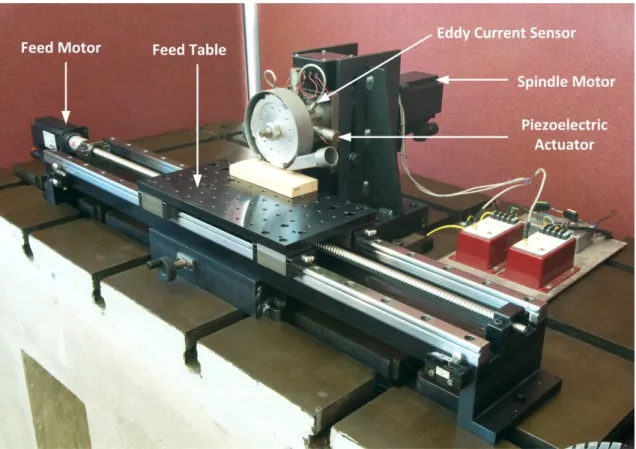
There is an existing small-scale mechatronic wood planing machine, which was originally designed by Hynek (2004). It was used to carry out preliminary investigations into alternative ways of improving the performance of industrial wood planing machines. The machine is equipped with four piezoelectric actuators for actively controlling the spindle unit. It is instrumented with two non-contact eddy current sensors for measuring the position of the spindle in the plane perpendicular to the spindle axis. The spindle is also equipped with an encoder for measuring its angular position. More details of the design and instrumentation of the machine can be found in Hynek (2004). The test rig has been re-designed for more realistic machining conditions (Figure 1.4) and is also used in this research for experimental validation.
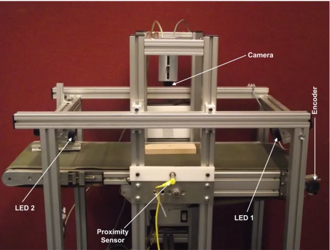
9 It is postulated in Jackson et al. (2002) that in-process surface quality monitoring could be used to provide a secondary control loop for wood machining operations so as to produce consistently high quality surface finish. This led to the design of a vision-based wood surface measurement system by Yang (2006). The system has been constructed to simulate a real machining environment for in-process surface profile assessments (Figure 1.5). Although the test rig was designed to measure dynamic surfaces, only static wood samples were assessed by Yang (2006). Further experiments are performed on the rig in terms of dynamic surface measurements.
10
1.5 Research Scope and Methodology
The research reported in this thesis starts from top level modelling and simulation work in order to examine the fundamentals of mechatronic design and adaptive control approach to the development of a high performance woodworking machine. The model-based approach has been chosen because it allows the design and testing of multiple solutions. Because this approach is software driven, it is possible to explore new concepts, investigate competing designs, and accurately predict the performance and behaviour of the system.
Firstly, a generic simulation algorithm for rotary wood machining process is created. The algorithm is used to investigate the effects of various machine defects on the resultant surface profile. It is also used to generate synthetic data for classification of products quality variation. Further work involves the use of machine vision techniques for in-process assessment of wood surface profile, and initial investigations into established techniques for characterising the defects through the analysis of the surface profile data. It is a well-known fact that there are challenges in using first principles to completely describe the behaviour of dynamic systems. Therefore, data-driven modelling through system identification and parameter estimation is used to develop models of the test rig. Finally, research efforts are directed towards the design of an overall control architecture for achieving an adaptive operation of the machine.
1.6 Proposed Control Architecture
The smart spindle unit of the wood planing machine shown in Figure 1.4 can be used for a number of possible applications. One of them is to achieve a surface waviness height reduction through periodic vertical movement of the cutterhead (Hynek, 2004). Secondly, it can be used to implement an active vibration control system in order to compensate for
11 the effects of disturbances, such as imbalance forces and cutting forces. The active vibration control is the main subject of study in Elmas (2008). The spindle unit can also be used for cutterhead inaccuracy compensation by displacing the cutterhead based on apriori knowledge of the difference between the finishing knives and a common cutting circle. This has not been thoroughly investigated by any of the previous researchers.
It is common knowledge that cutterhead inaccuracy and structural vibration are the main causes of defects on planed wood surfaces. Therefore, the work reported in this thesis is focused on the design of a single control system that is able to compensate for the cutterhead inaccuracy and at the same time minimise the effects of process disturbances, such as vibration. Although real-time cutter path optimisation and active vibration control have been separately studied by Hynek (2004) and Elmas (2008) respectively, this is the first attempt to design a control strategy that is capable of combining the real-time tool trajectory adjustment with process disturbance compensation. The proposed control architecture is shown in Figure 1.6.
12
Cutting Operation
Process Adjustment
High Level Learning/Reasoning
A-Priori Knowledge Machine Vision System
Process Output Samples
Sensors’ Data
Plant Operating Parameters Controller Gains
Surface Profile Recovery (Photometric Stereo) Heuristic Controller Reference
Signal Adjustment
Hybrid Controller
(Feedback + Feedforward Control Signal
Information Exchange Wood surface Images
Reference Adjustment
Secondary Control Loop
Primary Control Loop Reference
Signal
Figure 1.6 Proposed knowledge-based adaptive control architecture
The system consists of a primary and a secondary control loop. The primary control loop is based on real-time monitoring and adjustments of the plant’s process parameters. In the primary loop, sensors are used to measure and estimate the dynamic state of the plant; a controller is then used to drive the dynamic state of the plant to a desired state. The desired
13 state is pre-determined based on apriori knowledge of the machine characteristics and the process disturbances. The only way to ensure that the primary control yields the desired results (improved surface finish) is to have a feedback of the quality of the actual surface finish. The secondary loop then uses the feedback information to adjust the desired state of the plant in a heuristic or algorithmic manner. This approach enables the machine to produce consistently high quality surface finishes because it is able to adjust its actions based on the quality of its outputs.
1.7 Overview
This thesis consists of nine chapters organised as follows:
Chapter 1: The first chapter provides a general introduction to this research. It explains rotary wood machining and the main causes of poor surface quality. It then goes on to discuss the limitations of the current mechanical techniques used in the woodworking industry to improve surface finish quality. The main aim this research and how it is achieved is also discussed in this chapter.
Chapter 2: This chapter presents a review of the research activities that are relevant to the project. Focus is placed on the work related to the development of simulation models for wood machining, surface quality assessments, data processing techniques, and surface quality improvements through vibration control and real-time cutter path optimisation. The review also covers adaptive and intelligent control systems since they are very important elements of this research.
14
Chapter 3: A new simulation model for rotary wood machining is developed in this chapter. A generalised model for the existing circular arc theory is first formulated so that equations would not have to be derived for each defect case. The main purpose of this is to show that the circular arc theory can be used as a general-purpose simulator. This is then followed by the development of a new simulation model termed extended “circular arc theory”. The extended circular arc theory is more flexible and it represents the actual kinematics of the cutting process more accurately than the circular arc theory. Simulation results obtained from the extended circular arc theory are compared with those from the circular arc theory.
Chapter 4: The focus of this chapter is on the in-process measurements of cuttermarks on planed wood surfaces using machine vision techniques. Although this has earlier been investigated by Yang (2006), only measurements of static wood samples were reported. This chapter extends the measurement to moving wood samples and also identifies the key parameters that could possibly introduce measurement errors. One of the recommendations made by Yang (2006) is to find a way to extract the point-by-point albedo of wood samples so as to understand their reflective properties. Consequently, a suitable method that uses a three-image photometric stereo technique is developed to achieve this purpose.
Chapter 5: This chapter is focused on the development of two novel approaches for the analysis and characterisation of defects on planed timber surfaces. The general aim is to develop a software tool that can assist the machine operators to easily infer the machining conditions that produce a particular waviness defect on the workpiece. The two methods investigated are empirical mode decomposition (EMD) and principal component analysis (PCA). Due to the practical difficulty in generating sufficient amount of real machining
15 data, the techniques are applied to synthetic data generated using the simulation algorithm developed in chapter three. Necessary considerations for practical applications of the methods are also presented.
Chapter 6: Some characterisation tests performed to ensure that the improved rig produces the desired performances under operating conditions are reported in this chapter. The adaptive control system designed in chapter seven requires a state-space model of the plant. The previous researchers have modelled the test rig using finite element (FE) method. The problems with the FE approach are that it is time-consuming and may produce less accurate models of the plant. Moreover, it is not suitable for adaptive control of the plant. An experimental system identification method is used in this research to build mathematical models of the plant from measured input-output data.
Chapter 7: An optimal and adaptive control system for the active wood machining system is designed in this chapter. The primary objective of the control system is to compensate for cutting tool inaccuracy and also reject the effect of cutterhead vibration. The principle behind the cutting tool inaccuracy compensation is clearly explained, followed by the design of a suitable controller. The dynamic performance of the control system is tested both in simulation and on the actual test rig using a real-time rapid prototyping environment known as xPC Target.
Chapter 8: The results of further tests performed on the planer rig in order to determine the limits of its dynamic performance in terms of cutting speeds and vibration amplitudes are presented in this chapter. Results of real wood machining experiments performed in
16 order to physically investigate the effect of the real-time compensation on the resultant surface finish are also presented and discussed.
Chapter 9: This chapter summarises and concludes the research work and also identifies possible areas of further work.
17
2
Literature Review
_________________________________________________________________________
Apart from the Mechatronics Research Group at Loughborough University (MRGLU), two other communities conducting research in the area of wood machining have also been identified. These are the Wood Machining Institute, Berkeley, California, and the North Carolina State University Wood Machining and Tooling Research Program (WMTRP). Similarly to the MRGLU, the mission of the centres is to conduct research aimed at improving wood machining efficiency and wood utilisation.
Generally, research in metal machining has gained more attention than wood machining. Nevertheless, there are a number of practical investigations into rotary wood machining and the different types of waviness defects that can be produced. Suitable methods for assessing the quality of machined wood surfaces have also been investigated. A few other recent researches have focused on the improvement of the machined surface quality through dynamic optimisation of the cutter path and active vibration control. The purpose of this chapter is to review some of these research activities that are relevant to the current project. Outlines of the areas that are covered in this review are given below:
• Rotary wood machining
• Simulation and modelling algorithms for wood planing and metal machining
• Wood surface measurements and assessments
• Data and signal processing techniques
• Vibration control in wood and metal machining
18
2.1 Rotary Wood Planing – A Brief Review
The principle of the rotary machining of timber has been shown earlier in Figure 1.1 as a process during which wood chips are removed from an advancing workpiece by one or more knives clamped into the rotating cutterhead. The process would superficially appear to be a straightforward operation, which should not attract any significant research interests. Whereas, it is a complex machining operation that provides as much research challenges as metal machining operations.
2.1.1 Surface Waviness Quality
Planed timber surfaces comprise of waves known as cuttermarks. The surface waviness is primarily dependent upon the machining parameters, tooling conditions and any other shortcomings in the mechanical design of the machine that could lead to excessive vibration. The influence of the machining parameters, cutterhead inaccuracy and vibration on the resultant surface waviness has been studied extensively by Jackson (1986).
Other factors that can affect the waviness quality are the cutting forces generated during the machining process. The highly impulsive forces occur with each cutter engagement, and have been typically found to be of the order of 30N to 1000N. Some of the most significant parameters affecting cutting forces are chip thickness, cutter geometry, cutting direction, and the type of timber material being cut (Jackson, 1986).
The surface waviness is the key parameter used in the woodworking industry to determine the quality and production efficiency of the machine. A high quality surface finish is classified by cuttermarks width typically less than 1.5mm, and cuttermarks width greater than 2.5mm is typically considered to be a lower quality surface finish (Jackson et al.,
19 2002). The more the uniformity and consistency of the cuttermarks, the higher the quality rating of the produced surface finish (Figure 2.1).
Non-defective surface
Defective surface
Figure 2.1 Non-defective and defective wood surfaces
2.2 Waviness Simulation Algorithms
Established surface modelling and simulation algorithms for machining processes are required to investigate the effects of various cutting conditions, such as proud knives, spindle vibration, cutting edge wear, multi-knife cutting, and cutting forces on the resultant surface finish. There are some existing algorithms for simulating the topography of the surface produced by the wood planing process. Many simulation models have also been developed for metal milling operations.
A model termed surface-shaping has been developed by Ehmann and Hong (1994) for predicting the topography of the surfaces generated by metal milling operations. The generalised analytical model is based on the kinematics of the machining operations and the geometries of the cutting tools. The model takes into account errors during the machining process, such as machine vibration (chatter) and higher order motions. Similar
20 models for synthesising surface profile and roughness in high-speed end milling are described in Ismail et al. (1993) and Lee et al. (2001). The algorithms also consider the spindle vibrations, wear and spindle tilt run outs. It is shown that simulated surfaces and actual machined surfaces are in good agreement.
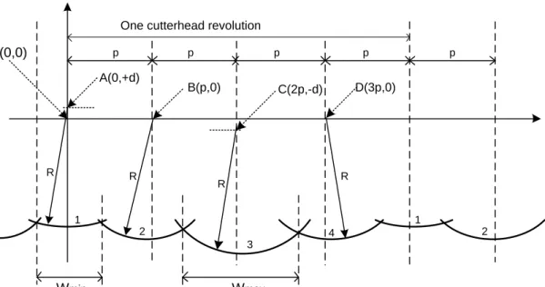
The simulation models that are of more interests are those for surface generation in wood planing. Due to the fact that the cutting edges are usually straight in wood planing compared to the helical shape in metalworking, 2D surface profiles are sufficient to describe the overall surface topography. The first model created for the rotary machining process is based on what is known as the circular arc theory (CAT). It was first used in Goodchild (1963) and later employed extensively in Jackson (1986) and Jackson et al. (2002) to simulate the effects of cutter errors and vertical cutterhead displacements on the quality of the surfaces produced by the wood planing process. The theory approximates the machined surface cuttermarks by using series of intersecting circular arcs with a radius equal to the radius of the cutting knives. The approximation is illustrated in Figure 2.2.
p p y x R R R R R W = p
21 Even though the CAT has the inherent ability to be used as a generalised simulator, it has only been used previously in such a way that different sets of equations are generated for each defect case (Jackson, 1986). This means that the model is not flexible and it cannot be used to simulate generalised defect cases. The CAT makes two simplifying assumptions. Firstly, it assumes that the movement of the workpiece has periodic discontinuities along the feed direction. Secondly, when using the CAT to simulate the effects of cutterhead vibrations, it also assumes that the vibration is a rectangular wave instead of a sinusoidal waveform. This means that the CAT represents periodic snapshots of the machining process rather than its actual kinematics.
More accurate algorithms were developed by Maycock (1993) and Brown (1999) . These algorithms are based on surface extraction from the knife tip path, generated as a series of discrete points. Very fine sampling of the cutterhead movement is required in order to achieve good spatial resolution of the resultant surface. The fine sampling is necessary because only an insignificantly small fraction of the knife tip discrete points produce the resultant surface profile. Sophisticated searching algorithms are employed to select those knife tip loci that form the overall resultant surface. It is worth mentioning that there are certain problems associated with the extraction algorithms as reported by the authors.
A more recent algorithm, which addresses some of the above problems in Maycock (1993) and Brown (1999), has been created by Hynek (2004). The algorithm approximates the machined surface by using a set of cubic splines. The algorithm can easily handle the effects of cutterhead vibration and cutterhead inaccuracy without the need for any complicated procedure to find the intersections between adjacent spline functions. However, the author (Hynek, 2004) clearly stated that further processing of the splines is
22 required in order to obtain information about the sizes of the cuttermarks. Fourier analysis is used to extract information about the frequency contents of the surface waveform. The need for further Fourier analysis of the surface waveform to extract the heights and widths of the cuttermarks is a major limitation of this algorithm. This limitation has motivated the creation of a new algorithm described in chapter three.
2.3 Surface Quality Improvements
A number of possible techniques have been devised to improve the quality of rotary planed timber surfaces. An overview of these techniques is presented in Figure 2.3. The categories in which the techniques explored in this thesis fall into are shown in the highlighted blocks.
The mechanical design and setup of the rotating components is very important because a major cause of vibration during the machining process is mass imbalance. It is a condition that occurs when the mass of any of the rotating components is unevenly distributed around the centre of rotation, generating a sinusoidal forced vibration along the cutting plane. There are always some inherent imbalances in the system, which cause the cutterhead to vibrate during the machining process. An active vibration control technique is investigated in this thesis.
The accuracy of cutter tracking is traditionally being improved by jointing the cutting edges in order to minimise the effects of cutter inaccuracy. This process has some disadvantages mentioned earlier in chapter one. For this reason, a new technique that modifies the trajectory of the cutting tool in real-time is explored in this thesis.
23
Surface quality improvements
Vibration control Tooling accuracy improvements
Real-time optimisation of process kinematics
Improved machine tool design (e.g increased
stiffness)
Passive vibration control (e.g tuned mass dampers,
viscous dampers, dynamic absorbers)
Active vibration control (e.g. active magnetic
bearings, fully active piezo actuator control)
Operating outside the regimes where resonances
are being excited
Semi-active control (e.g.
varying the stiffness of piezoelectric actuators)
Use of appropriate tooling technologies (e.g.
Hydrogrip tooling)
Accurate tooling preparation (e.g grinding
the cutters in the cutterhead)
Jointing the cutters (i.e.
dressing the cutting knifes in the cutterhead Real-time periodic horizontal displacement of the cutterhead Real-time periodic vertical displacement of the cutterhead
Techniques explored in this thesis
Figure 2.3 Surface quality improvement techniques
2.4 Real-time Optimisation of Process Kinematics
Real-time modifications of the rotary machining process have been investigated by earlier researchers. The first one, being the introduction of additional horizontal cutterhead movement, is reported in Brown (1999), Brown and Parkin (1999), and Brown et al. (2002). The principle of the cutterhead horizontal movement is such that when each knife engages with the workpiece, the cutterhead is advanced in a horizontal plane across the timber surface by a magnitude in the order of the cuttermarks width (Figure 2.4). This is
24 followed by a retraction of the cutterhead prior to the next knife contacting the workpiece (Figure 2.5). The frequency of these forward and backward movements is related to the knife passing frequency of the cutterhead.
Results show that the modified machining process produces trough-like cuttermarks instead of the conventional scallop-shaped ones. The cuttermarks have reduced heights compared to the ones produced by conventional planing process under the same tooling and machining conditions. It was reported that a perfectly flat surface would be possible if the cutterhead could be stopped from rotating during the horizontal movement. However, the inertia and the kinetic energy due to the cutterhead mass (20-80kg) and rotational speed in the range of 62-1800rad/s would make this to be impracticable. Moreover, the magnitude of the movement is related to the cuttermarks width and its frequency is related to the cutting speed. Therefore, high-speed machining will require actuator with significantly short response time.
25 Figure 2.5 Cutterhead retract detail (Brown et al., 2002)
The modification of the machining process kinematics was also studied by Hynek (2004), but a vertical cutterhead movement was introduced instead. The principle of the proposed method is that the cutterhead starts moving upward in a sinusoidal manner when the knife tip is at the start of the cutting path. The cutterhead then starts moving downwards in a similar manner immediately after the knife tip reaches the midpoint of the cuttermark. The idea is illustrated in Figure 2.6.
26 The author (Hynek, 2004) pointed out that the proposed method is theoretically capable of completely removing the surface waviness if the vertical cutterhead movement is such that the knife tip follows a straight line for a distance equal to at least the length of the cuttermark. Similarly to the case of additional horizontal movement, the relatively large mass of the cutterhead needs to be controlled within a very narrow time window. The speed of response of commercially available actuators might not be sufficient for high-speed machining. Insertion of the actuators into the knives might provide a more viable solution but this is not the focus of the investigation to be carried out in the current project.
2.5 Vibration Control
Engineers at different levels approach the subject of machine vibration in different ways. From a maintenance engineer’s point of view, vibration standards and guidelines are used to monitor the health of equipment for their timely repair and refurbishment. This has moved industries from preventive and corrective maintenance into predictive maintenance practices, which reduce plant downtimes and premature replacement of machine components considerably.
From a design engineer’s point of view, vibrations have ever since been major limiting factors in the performance of many industrial machines. A machine design engineer has to recognise the potential sources of vibration and control them within acceptable limits. Vibration occurs in any machining process and it has severe implications on surface quality, tool life and process capability. Minor imbalances in rapidly rotating parts can cause significant vibrations and high dynamic loads on the machine tool components (Rojas et al., 1996). Vibration can also be caused by the cutting forces generated as a result of the relative motion between the cutting tool and the workpiece.
27 The presence of vibration during machining operations has made it difficult to attain the much desired requirements of productivity and surface quality. Advances in machine tool materials and spindle motor power have opened the possibility of substantially reducing production time and cost through high-speed machining. However, vibration characteristics of machining systems are major limiting factors preventing the utilisation of these advances to full advantage. In metal cutting, vibrations often lead to cutting instability known as machine tool chatter. A detailed technical insight into the effects of vibration in rotary wood machining is reported in (Jackson et al., 2007).
The control of vibration is very important to improve performance efficiency and productivity. The effects of vibration can be minimised in two ways. The first is through modification of the cutting process and the second approach is through modification of the machine dynamic characteristics (Sims and Zhang, 2003).
In the first approach, models that predict vibration (stability lobes) are used to choose cutting conditions that avoid excessive vibration. This involves online optimisation and variation of the cutting parameters (cutting speed and feed speed) so that the cutting process adapts to the dynamic properties of the structure and the machining process always lies in a stable regime (Rashid and Nicolescu, 2006). Examples of such control approaches can be found in Al-Regib et al. (2003) and Ismail and Ziaei (2002). The cutting parameters variation approach is not suitable for the rotary wood planing where constant speed is required to obtain consistent cuttermarks.
28 In the second approach, the structure of the machine is modified in some ways so as to improve its dynamic characteristics (stiffness and damping). The common classifications of this approach as found in literature are passive, active and semi-active methods. These classifications are based on the amount of external power required for the vibration control system to perform its functions. A simple structure with the three vibration control methods is shown in Figure 2.7.
m c k x m c k x m c(t) k(t) x u(t) Point of attachment (a) (b) (c) Vibration control Primary system
Figure 2.7 A structure with three vibration control methods: (a) passive, (b) active, and (c) semi-active configuration (Jalili, 2002)
2.5.1 Passive Vibration Control Method
The passive methods include the use of dissipative devices, such as viscoelastic materials and viscous dampers, as well as reactive devices, such as tuned mass dampers and dynamic vibration absorbers (Lee et al., 2001). Magnetic dampers and shunted piezoceramic dampers are other elements that are commonly used. Dampers absorb the vibration energy from the primary system and gradually dissipate the energy in form of heat
29 Vibration problem may be solved in part through proper machine design, which stiffens the machine structure (Pettersson et al., 2001). Vibration in circular wood sawing has been minimised by improving the design of the saw blade such that the stiffness can be increased, thereby shifting the resonance frequency to a higher level in order to minimise vibration (Renshaw, 1998). This approach of altering the dynamic characteristics of the saw blades in a passive way restricts the frequency range and the amplitude of vibration that can be controlled.
Tarng et al. (2000) investigated the use of a piezoelectric inertia actuator, mounted on a cutting tool to act as a tuned vibration absorber for the suppression of chatter in a turning operation. For this system to be effective, the vibration absorber must be tuned such that its natural frequency is equal to the resonance frequency of the cutting tool. The passive vibration control method is very effective within the frequency region of its highest sensitivity but may be of little use at lower frequencies unless devices with high masses are used (Moheimani et al., 2004).
A particular feature of the passive method is that there is no feedback between the vibration absorber and the structure to be controlled. A vibration control system is always required to operate over a wide band load and frequency range, which cannot be met with a single choice of stiffness and damping provided by the passive devices (Rojas et al., 1996). A phenomenon known as “de-tuning” often reduces the effectiveness of passive vibration control systems. This occurs due to deterioration of the structural parameters or variations in the excitation frequency of the primary system. Passive vibration control systems lack versatility because they are unable to adapt to changes in the disturbance or structural