Introduction
In the world of telecommunications, the two fastest growing areas are fixed and mobile IP services. The main reasons for this are deregulation, increased competition, mar-ket demand for broadband services, and the introduction of new technology.
New fixed wireless broadband technolo-gies give operators an opportunity to address the issue of bandwidth in present-day access networks. The growing demand for band-width in the access network is mainly due to a surge in Internet and intranet traffic, LAN-to-LAN interconnect, and a mount-ing interest in voice over IP (VoIP). In other words, the market is demanding an access network solution that can carry different
kinds of broadband multimedia service. Nu-merous activities are underway to extend fiber networks and to introduce digital sub-scriber line technologies (xDSL) into exist-ing copper networks. However, by compar-ison, a radio-access alternative offers several significant benefits:
• Time to market—the rapid deployment of new broadband services will be crucial to the success of new operators. By de-ploying an efficient new radio-access sys-tem, operators can reduce time-to-market for new services.
• Ownership of the infrastructure also im-plies “ownership” of the end-user, as well as independence from other operators and from the unbundling process of the local loop.
• Low cost—fiber is expensive to deploy and copper is expensive to maintain. The main cost of radio access is the equipment. Furthermore, this cost is falling in pace with the development of new technology. • Flexibility, pay as you grow—the infra-structure can easily be redeployed as need-ed.
• Efficient use of the radio spectrum— Ericsson’s broadband radio technologies employ statistical multiplexing over the air interface, which allows operators to sell data services that require high peak data rates.
Fixed wireless access for broadband services
Magnus Grandin
Wireless broadband access (WBA) technology is rapidly taking root in a fertile global marketplace. It can easily provide an effective platform from which to expand existing infrastructure, or serve to provide infrastructure in hitherto under-served areas. In the world market, the potential of WBA technology is enormous, in particular, because it allows cable-like multi-media services without the cable.
The author describes Ericsson’s Beewip solution, which uses fixed wireless access to bring broadband services to small office/home office and small enterprise customers.
ATM Asynchronous transfer mode BAE Base station antenna element BOU Base station outdoor unit BRC Base station radio controller BS Base station
BSW Base station switch
BWLL Broadband wireless local loop CATV Cable TV
CDMA Code-division multiple access C/I Carrier-to-interference ratio DSL Digital subscriber line E1 ETSI 2 Mbit/s interface E3 ETSI 34 Mbit/s interface
FDMA Frequency-division multiple access
FH-CDMA Frequency hopping CDMA GFSK Gaussian frequency shift key
GK Gatekeeper
GW Gateway
H.323 ITU recommendation for multi-media applications
IF Intermediate frequency IP Internet protocol
ISDN Integrated services digital network
LAN Local area network
LMDS Local multipoint distribution sys-tem
LOS Line of sight MAC Media access control
OAM Operation, administration and maintenance
OLOS Obstructed line of sight PoP Point of presence POTS Plain old telephone service PSTN Public switched telephone network SIU Subscriber indoor unit
SNMP Simple network management pro-tocol
SOHO Small office/home office SOU Subscriber outside unit SU Subscriber unit
TDMA Time-division multiple access TOS Type of service
VoIP Voice over IP WAN Wide area network WBA Wireless broadband access xDSL Collective term for the family of DSL
technology BOX A, ABBREVIATIONS
• Radio technology permits selective ac-cess; investments do not rely on multi-connections. Furthermore, radio can reach where other technologies cannot, for in-stance, beyond CATV coverage, where fiber is too expensive to deploy and where xDSL is unsuitable.
In 1999, several important developments overlapped and intertwined to create the fiber of a new marketplace:
• licenses in the 3.5 GHz frequency band for fixed wireless access were auctioned in Europe and Latin America;
• end-users began demanding low-cost, “always-on” broadband access;
• the dominance of circuit-switched traffic was eroding in developed countries as were per-minute and by-distance charg-ing schemes;
• deregulation enabled new operators to target high-margin customers and build growth from there;
• technological advances enabled the pro-duction of mass-market radio at 3.5 GHz; and
• previous venture-capital investments in wireless local loop and wireless LAN had created interesting packet-radio plat-forms on which to build complete radio systems.
To meet the market requirements quickly, Ericsson chose to use off-the-shelf technol-ogy and products in all relevant sub-systems. Our focus would be on system in-tegration and radio network performance. Open-standard interfaces and protocols pro-vided a basis for flexibility, scalability, and system migration. The intent was to build a packet-data system that can provide real-time voice services (not the other way around). IP was the obvious choice of core traffic protocol—to provide connectivity and a multiservice system.
Beewip
Beewip provides a transparent access medi-um for different types of IP service. Wire-less Ethernet, based on IEEE 802.11, car-ries IP traffic over the air interface. With its advanced system architecture, Beewip supports dynamic bandwidth allocation and provides continuous (always-on) con-nection at data rates of up to 3 Mbit/s per subscriber. The system makes efficient use of the radio spectrum and offers high qual-ity of service.
Beewip is based on the Internet protocol and open standards, which facilitates
evolu-tion in terms of services, capacity, and func-tionality (Table 1).
System overview
The system contains three main groups of subsystems or nodes (Figure 1):
• The subscriber unit (SU), which consists of a subscriber outdoor unit (SOU) and a subscriber indoor unit (SIU), is located on the end-user premises.
• The base station (BS) includes a base sta-tion radio controller (BRC), a base stasta-tion switch (BSW), base station outdoor unit (BOU), and base station antenna elements (BAE).
• Operation, administration and mainte-nance (OAM) system hardware and soft-ware.
The subscriber unit is connected to the base station over the air interface. At the base sta-tion, the base station switch concentrates traffic and routes it to the point of presence (PoP). However, before traffic is routed, it is converted from the 10BaseT Ethernet for-mat to the appropriate transmission media protocol. Figure 1 shows how the Beewip system is implemented into existing net-works. The PoP concentrates data and voice traffic and controls traffic flows. It also fil-ters traffic at the firewall and shapes traffic.
Frequency band: 3400 - 3600 MHz Duplex spacing: 100 MHz Modulation: Gaussian frequency
shift keying (GFSK) (1, 2 or 3 bits/symbol) Bit rates: 1, 2 and 3 Mbit/s Sub-channel
spacing: 2 MHz
TABLE 1, RADIO CHARACTERISTICS
Beewip™ OAM BSW Pop GW GK Product support services and tools BRC
BOU BAE SIU
SOU
BS SU
Internet
PSTN Figure 1
Telephony-related data packets are for-warded to the appropriate media gateway (GW); similarly, signaling data is forward-ed to the appropriate gatekeeper (GK).
The subscriber unit
Subscribers gain access to services via the subscriber unit located on their premises. Various types of subscriber units are avail-able offering combinations of data and voice connections. The number of data connec-tions is determined by the maximum num-ber of (MAC) addresses that can be con-nected to the subscriber unit.
The subscriber unit consists of an outdoor and an indoor unit. The subscriber outdoor unit includes a directional antenna with 17 dBi antenna gain, which provides a hor-izontal and vertical opening angle of 20°. The antenna must be installed properly and aligned with the base station. The radio front-end, which provides 27.5 dBm output power (0.5 W), is attached to the antenna to minimize feeder cable attenuation. The subscriber indoor unit is connected to the outdoor unit by intermediate frequency (IF) at 440 MHz over cable. The indoor part in-cludes the IF stage and radio baseband modem, a 10BaseT interface, and a tele-phony interface to customer equipment. It also includes a power supply. The radio and interface platforms, based on the wireless Ethernet standard (IEEE 802.11), are taken from wireless LAN.
The subscriber unit was designed to have low installation and network maintenance costs. The use of standard components for the air interface (IEEE 802.11), computer interface (10BaseT), and wireless LAN product platforms ensure cost of scale and rapid time to market. An important feature of the subscriber unit is that it supports phony via a standard (analog) plain old
tele-phone service (POTS) interface. Analog voice is converted in an H.323 client im-plemented in the subscriber unit. Telephony-related signaling and traffic are sent to a media gateway over IP over the air. To control telephone sessions, the H.323 client communicates with the gateway or gatekeeper. The SU client and the gate-way/gatekeeper communicate call set-up, call release, speech coding, and so on.
Voice-related services put requirements on the transmission quality all the way from the interfaces at the subscriber unit to the media gateway in the core network. Since voice and data traffic in most parts of the network—and, in particular, over the radio link—share the same access medium, the al-location of resources must be controlled. Therefore, to handle different traffic classes in the subscriber unit, the IEEE 802.11 pro-tocol has been modified.
Base station
The base station consists of a radio con-troller, a switch, outdoor units, and anten-na elements. The radio controller includes • radio baseband parts;
• the synchronization of sectors—to elimi-nate inter-base-station interference; and • power supply.
IEEE 802.11, which serves as the radio con-troller base for media access, works up to layer 2. As mentioned above, it has been modified to handle different service classes. The base station allocates capacity for voice at call set-up by means of a polling mecha-nism that regularly interrupts data traffic to allow subscriber units with ongoing voice sessions to send voice packets.
An interesting characteristic of the air in-terface is the decentralized MAC layer from Ethernet made for pure data over cable. The MAC layer has been migrated for use in wireless environments via the modified IEEE 802.11 standard. Each base station works independently. Semi-orthogonality (orthogonality reduces interference and col-lisions) is obtained by means of a random frequency-hopping technique called FH-CDMA.
FH-CDMA, which is a combination of time-division multiple access (TDMA), frequency-division multiple access (FDMA) and code-division multiple access (CDMA), is particularly suited to fixed radio net-works. A re-transmission mechanism is also included, since the system presumes that collisions will occur. Indeed, at times, the system actually forces collisions to occur in
Figure 2
certain subscriber units—to prevent dis-crimination in the system.
The base station switch is a very flexible sub-node that can be described as a layer 3 switch, router, or WAN access. The WAN access function is mainly a protocol conver-sion to the appropriate transmisconver-sion inter-face. The main switch functionality, imple-mented at layer 2, pertains to switching and traffic control. Tagging is used to exchange packet-data-related information (for exam-ple, does the packet carry real-time traffic?) between the transmission and radio net-works. The base station switch also provides a wide range of interfaces for transmission. Support for additional interfaces includes Ethernet, fiber, E1, E3, and ATM.
Ordinarily, the antenna arrangement of the base station has six sectors evenly dis-tributed around the horizontal circle. How-ever, because traffic is seldom evenly dis-tributed around base station sites, two kinds of antenna can be used: one with a 60° and another with a 120° horizontal opening angle. The antennas and antenna arrange-ments facilitate flexible migration to sup-port growth in the system or capacity.
The base station is housed in a single 19-inch cabinet that is small enough to be trans-ported by air-freight. The cabinet can be in-stalled indoors and out. An air conditioning unit can be installed in the door (the cabi-net is configured at the factory). The AC door can be detached from the cabinet dur-ing transport, for instance, to allow it to be carried up stairs.
Operation, administration and maintenance
The OAM part enables the operator to re-motely configure the nodes of the entire ac-cess network, to upgrade software, and on the whole, to control and monitor all traffic in terms of fault- and performance-management functions. The OAM part is based on the simple network management protocol (SNMP) and runs on the Windows NT platform.
System performance
Services
The requirements put on a system like Beewip are complex: Expectations change over time, as do services, means, and tools. Users of the Internet have learned to accept that speed and availability are not guaran-teed; they have also learned to accept slow
dial-up access connections. Likewise, users of mobile voice services have learned that coverage is not comprehensive and calls can be dropped. By contrast, users of fixed tele-phony do not accept anything less than (near) total availability and insignificant delay—they do, however, accept a slow emergence/introduction of new services.
In the Beewip system, users must learn to utilize “always-on” and broadband services, which are important features. At the same time, voice services will be different from those of the traditional public switched tele-phone network (PSTN). But the delay, voice coding, and so on cannot be significantly different. In reality, the delay of voice in Beewip will be slightly greater in Beewip than in fixed connections, and availability will not be 99.999%. On the other hand, service evolution and price levels will be very different when IP is used to carry voice and data.
Radio network
Path loss
The building of fixed radio networks at 3.5 GHz with near line-of-sight deployment is significantly different from most other radio networks. Since the subscriber units are fixed, careful placement will create a reliable radio link. However, a car parked on the street next to the house, an open window in
Figure 3
Obstacles in first Fresnel zone—obstructed line-of-sight (OLOS) scenario. The OLOS sce-nario allows for easy and inexpensive installation of the base station antenna element (BAE) and subscriber outside unit (SOU).
the building across the street, or leaves ap-pearing on trees between the base station and subscriber unit can have considerable impact on signal path loss. Fixed radio networks can thus be regarded as mobile systems whose antennas are fixed but whose environment changes. The Doppler shift is insignificant, but the fading of fixed radio systems has sim-ilar dynamics as mobile systems—although with significantly longer time constants, such as seasons.
Interference
As in any other radio network, heavy traffic in fixed radio networks creates interference. In mobile networks, mobile terminals move within the coverage area—sometimes a ter-minal is at the cell border with a poor con-nection; at other times the terminal is at the center of a cell with a perfect connection. However, in a fixed network, a terminal at the border of the cell will always remain at the border of that cell. And interference will almost always originate from the same source.
Beewip solution
By means of multi-modulation schemes with automatic fall-back, Beewip can
dy-namically choose the best possible modu-lation for each subscriber unit. Frequency-hopping techniques equitably distribute internal interference and capacity among subscribers. Since the base station is not synchronized in the network, the interfer-ence pattern is semi-random. The colli-sions that occur from this configuration are distributed over time and area to en-sure that each subscriber unit receives the service it has been granted, even during busy hours. The frequency-hopping tech-niques can also be employed to eliminate external interference, for example, by shifting to a carrier frequency with less fading.
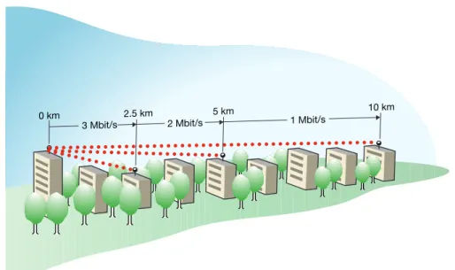
Table 2 shows the maximum transmis-sion range at different bit rates—using the nominal radio characteristics of the system with a 60° antenna and an OLOS path-loss model.
As mentioned above, Beewip is a packet-oriented system that employs FH-CDMA radio technology. In terms of capacity, the pa-rameter of greatest interest is the carrier-to-interference ratio (C/I). The gross bit-rate val-ues vary in different deployment scenarios.
The results of a simulated worst-case
sce-LOS Line of sight—to use free-space (LOS) propagation, the first Fresnel zone must be free of obstacles OLOS Obstructed line of sight—that is, the
visual path is free but obstacles (houses, trees, and so on) exist in the first Fresnel zone between the trans-mitting and receiving antennas. BOX B, LOS AND OLOS
0 km 2.5 km
3 Mbit/s 2 Mbit/s 1 Mbit/s
5 km 10 km
Figure 4
Line-of-sight conditions permit transmis-sion ranges of up to 10 km.
nario, based on a large network, minimal amount of bandwidth, and heavy traffic show that the average gross bit-rate in an OLOS deployment is 2.2 Mbit/s.
Obviously, in a more typical traffic sce-nario, there is less interference, which means that traffic can be sent at higher bit-rates. Similarly, a network with fewer base stations and greater bandwidth can be ex-pected to yield a gross bit-rate close to 3 Mbit/s.
Deployment
The Beewip system adheres to a cellular de-ployment structure in which multiple cells provide coverage to a geographical area. Each cell contains one base station and sev-eral base station antenna elements (BAE), each of which is driven by a base station out-door unit. The base station antenna elements are sector antennas that cover either a 60° or 120° sector.
The number of subscribers that can be connected to a Beewip base station with six sectors depends on the
• manner of deployment; • terrain;
• distance between base stations and sub-scribers; and
• current data traffic load—subscriber be-havior, services offered, and so on.
Conclusion
To be successful in the new telecoms world, operators need to focus on new broadband services. Ericsson’s Beewip product family has been optimized to carry IP traffic over a radio interface. The integration of radio and IP technology offers innovative operators very rapid and cost-effective deployment of new broadband IP services.
Beewip gives operators a competitive alternative solution for residential, small office/home office and small enterprise cus-tomers.
Its “always-on” connection (up to 3 Mbit/s per subscriber) enables end-users to exploit the benefits of a wide range of multimedia applications. Beewip, which operates in the 3.5 GHz frequency band, makes efficient use of spectrum and provides high quality of service. It is based on IP and open stan-dards, which facilitates the evolution of ser-vices, capacity, and functionality.
Bit rate Transmission range
1 Mbit/s 10 km
2 Mbit/s 5 km
3 Mbit/s 2.5 km
TABLE 2, MAXIMUM TRANSMISSION RANGE AT DIFFERENT BIT RATES
Beewip is a trademark owned by Telefonak-tiebolaget LM Ericsson, Stockholm, Sweden. Windows NT is a registered trademark of Microsoft Corporation.