Cyber Crime Scene Investigations (
C
2SI
) through Cloud Computing
Xinwen FuUniversity of Massachusetts Lowell [email protected]
Zhen Ling Southeast University, China
zhen [email protected]
Wei Yu Towson University
Junzhou Luo Southeast University, China
Abstract—Cloud computing brings opportunities for net-work forensics tracing Internet criminals in the distributed en-vironment. We may use the new “pay-as-you-go” model of the cloud computing to deploy the on-demand cyber surveillance sentinels and conduct distributed traceback in complicated cyber crime scene investigations. To trace criminals abusing anonymous communication networks such as Tor, law enforce-ment can deploy high-bandwidth Amazon EC2 sentinels into the Tor network. Some sentinels are configured as Tor entry guards and others work as Tor exits nodes. With the high bandwidth and appropriate number of such sentinels, we can achieve a required probability that a Tor circuit passes through an entry sentinel and an exit sentinel in order to capture the suspects. The proposed “pay-as-you-go” traceback model is cost-effective since the investigation may last for just hours with effective traceback techniques. Our experiments demonstrate the feasibility of this new traceback strategy through the cloud. Keywords-Cloud Computing, Network Forensics, Traceback, Tor, Sentinels
I. INTRODUCTION
Cloud computing brings opportunities for network foren-sics tracing Internet criminals in the distributed environment. We may use the new “pay-as-you-go” model of the cloud computing to deploy the on-demand sentinels and conduct distributed traceback in complicated cyber crime scene in-vestigations.
Cloud computing provides users different venues and services to conduct computing on the Internet. Cloud com-puting can be viewed as ready-to-go information technology for purchase as a service over the network [1]. Such a computing model boasts infinite pay-as-you-go computing resources available on demand for any span of rent time [2]. Users don’t need to purchase hardware, software and configure them locally. Via cloud computing, software, hardware and the configured system are purchased as a service. Users can rent a server or thousands of servers via cloud computing providers around the world. The demanded computing service can be started and stopped at any time at will. The application running with the cloud can be a datacenter such as email and corporate database or CPU thirsty computing on powerful servers.
Cloud computing service is often delivered through virtual machines (VM) because of VM’s flexibility and ready-to-go nature. Different applications services can be delivered as
ready-to-go packages or assembled across the Internet to achieve a specific computing goal. The computing can scale down and up via the cloud computing application software in charge of the service software and hardware.
Various cloud computing services are currently available. Amazon EC2 (Amazon Elastic Compute Cloud) [3] is at one end of the service spectrum. EC2 provides whole VMs for purchase. A user has full control and root privilege of the VMs. Read-to-go software are also available for purchase to run on VMs. The billing of the service is based on the rent time and network bandwidth usage. Google App Engine [4] is at the other end of the application spectrum. Users develop web sites via Google provided APIs in Java and Python and Google hosts the web sites across its infrastructure and take cares of the load balancing as web usage scales up and down. That is, the hosting and load balancing are transparent to users. Windows Azure Platform [5] is in the middle of the application spectrum. It provides a group of cloud technologies, each providing a specific set of services to application developers. It can be used both by applications running in the cloud and by on-premises applications. Three components of the platform are Windows Azure, SQL Azure and Windows Azure platform AppFabric [6]. Windows Azure provides a Windows-based environment for running applications and storing data on servers in Microsoft data centers. SQL Azure provides data services in the cloud based on SQL Server. Windows Azure platform AppFabric provides cloud services for connecting applications running in the cloud or on premises.
In this paper, we explore the application of digital foren-sics through cloud computing. As wireless, mobile com-puting, and the Internet become pervasive and ubiquitous, the number of cyber crimes has also been increasing drasti-cally. These crimes include sexual exploitation of children, intellectual property theft, identity theft, financial fraud, and espionage, etc. Digital forensics studies techniques that en-able the investigation of an alleged crime or policy violation involving digital data. It serves an important role in industry, federal and state law enforcement, and other national cyber-defense forces.
We can divide digital forensics techniques into two cate-gories: computer forensics and network forensics. Computer forensics is a relatively established area. The traditional consensus was that computer forensics is about collecting
and analyzing evidence on standalone mediums such as hard drives, flash memory, computer memory, etc. As the technol-ogy advances, today’s PDAs and smartphones also possess large storage capability. Techniques collecting evidence from these devices can also be included into the category of computer forensics.
Network forensics is a growing area of digital forensics. Network forensics is about tracing and locating criminals on the Internet. Cyber crimes often involve complicated crime-scene investigations. Criminals may abuse profes-sional anonymous communications systems such as Tor [7], [8], Anonymizer [9], I2P [10], BitBlinder (Anonymous BitTorrent) [11] and AnoTorrent (anonymous P2P Bittorrent) [12], which were originally designed for protecting network users from identity theft and profiling. Network forensics over such systems again requires the application of cutting-edge research. Collecting evidence from networks is already a challenging problem since the evidences may be volatile: packet logging is a formidable task given the extremely large volume of network data and network packets are often not logged. Tor and Anonymizer are the most popular two anonymous communication networks while the number of users of other systems and networks is limited and their core techniques for anonymity are also similar to Tor and Anonymizer. Without loss of generality, we use Tor as an example to explain our research for forensic investigation of anonymous communication systems whenever necessary.
This paper is focused on network forensics. We explore the opportunities that cloud computing brings to us in tracing cyber criminals hiding in the dark cloud such as abused anonymous communication systems. We propose to deploy on-demand Tor sentinels into the cloud. e.g., those provided by Amazon EC2. When crime activities are intense over the dark cloud and it is time to conduct network forensic investigations, Tor sentinels will be activated. Such investi-gations utilize the pay-as-you-go model of cloud computing and they are cost-effective since the investigation can last for just hours with effective traceback techniques. The law enforcement does not need to deploy massive surveillance infrastructure which can be idle for most of time and incur overwhelming maintenance cost. Although Planetlab [13] can be one type of cloud computing platform and hosts the sentinels, it has limited bandwidth capability, has rigid policies on its usage and is not appropriate for the network forensic traceback. For example, Planetlab nodes cannot be used as Tor exit sentinels, which are critical for the success of the traceback.
This paper makes the following contributions:
• We are the first to formally propose to use cloud computing services to help the cyber crime scene investigations (C2SI) and define a set of meaningful problems. Sentinels can be set up within the cloud and monitor crimes on the Internet in a cost-effective way. • We are the first to analyze how to set up Amazon EC2 sentinels monitoring the abuse of the Tor network. Such
abuse is throttling the healthy Tor development. For traceback through Amazon EC2 nodes, our theoretical results fully match the results from Tor algorithm simulations.
The rest of this paper is organized as follows: Section II introduces the basic idea of traceback through the cloud. Section III analyzes optimization of cloud computing in-vestment for maximum traceback results using Amazon EC2 over Tor. Section IV evaluates the strategy of network forensics through cloud computing. We conclude this paper in Section V.
II. TRACEBACK THROUGH THECLOUD
A. Basic Idea
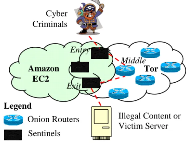
Figure 1 illustrates the basic idea of traceback through the cloud. Law enforcement deploys high-bandwidth surveil-lance sentinels by purchasing the cloud computing service from providers such as Amazon. Those sentinels become part of the anonymous communication network such as Tor, which is the focus of this paper. Some are configured as Tor entry guards and others work as Tor exits nodes. With the high bandwidth and appropriate number of such sentinels, we can achieve a required probability that a Tor circuit passes through an entry sentinel and an exit sentinel. The law enforcement can then employ various efficient and effective traceback techniques [14], [15], [16] and determine if the evil attacks the victim server or downloads illegal content from a server. Amazon EC2 Tor Cyber Criminals Illegal Content or Victim Server Entry Middle Exit Sentinels Onion Routers Legend
Figure 1. Amazon EC2 for Network Forensics
To make this strategy work, law enforcement should max-imize the probability that a suspect circuit selects sentinels as entry and exit nodes. Denote this probability as catch probability. There are a few challenging issues:
• A Tor circuit does not select two class C addresses in a subnet for a circuit. Does EC2 have enough different IP addresses?
• What is the smallest number of EC2 sentinels to purchase given a required catch probability? That is, we need to optimize our investment on cloud computing and maximize the profit.
We introduce the EC2 IP range below and discuss the optimization problem in Section III.
B. IP Range of Amazon Elastic Compute Cloud
Within Amazon Elastic Compute Cloud (EC2), Elastic IP addresses are static IP addresses designed for dynamic cloud computing. An Elastic IP address is associated with a user account not a particular instance, and users control that address until they choose to explicitly release it. To provide fault tolerance, EC2 provides its virtual instances across multiple data centers organized in so-called region and availability zones. Region is comprised of several availability zones. Two virtual instances running in different availability zones are guaranteed to be executed in different data centers. Of the eight availability zones, six are located in the U.S. East, one is in the U.S. West and one are in Europe.
Unlike traditional static IP addresses, however, Elastic IP addresses allow users to mask instance or Availability Zone failures by programmatically remapping user public IP addresses to any instance in user accounts. Rather than waiting on a data technician to reconfigure or replace the user host, or waiting for DNS to propagate to all customers, Amazon EC2 enables users to engineer around problems with a user instance or software by quickly remapping an Elastic IP address to a replacement instance [3].
To find the IP range of Amazon EC2 robustly and flexibly, we can google the keywords “Amazonaws”, “IP Range”, “Net Range” and so on to find the public IP addresses or domain names of the Amazon Web Services. Then, we use whois [17] to find out the IP ranges corresponding to the known EC2 domain names. Table I shows that the searched IP ranges by using Google and Whois are almost the same as the Amazon EC2 official IP range [18].
Table I
AMAZONEC2 PUBLICIP RANGES
Region Official IP Ranges IP Ranges from web 204.236.128.0/18 204.236.128.0/18 72.44.32.0/19 72.44.32.0/19 US East 67.202.0.0/18 67.202.0.0/18 (Northern Virginia) 75.101.128.0/17 75.101.128.0/17 174.129.0.0/16 174.129.0.0/16 204.236.192.0/18 204.236.192.0/17 US West (Northern California) 216.182.224.0/20 204.236.128.0/17 EU (Ireland) 79.125.0.0/17 79.125.0.0/18
From Table I, we can see that EC2 has a wide range of IPs and meet the requirement of traceback via sentinels.
III. OPTIMIZATION OFCLOUDCOMPUTING
INVESTMENT FORMAXIMUMTRACEBACKRESULTS
In this section, we first present the Tor path selection algorithm. We then discuss how to optimize the catch probability given a fixed number of Amazon EC2 nodes as the cloud computing investment.
A. Tor Path Selection Algorithm
Algorithm 1 presents the path selection algorithm which chooses routers in a specific order given a desired path length that is 3 by default. Tor does not choose the same router twice for the same path [19]. From Algorithm 1, we know that to create a circuit, Tor selects an exit node, an entry node and then a middle node in order. Algorithm 2 presents the algorithm ofPreprocessing a List for Selecting the Exit Node. To improve the circuit throughput, Tor uses bandwidth weighted Algorithm 3 to choose the exit and entry node from the corresponding candidates. Algorithm 4 describes the selection of entry or middle nodes for a circuit. Algorithm 1Tor Path Selection Algorithm
1: Create a new circuit and initialize global circuit ID, etc. 2: Add the circuit into the global circuit list
3: Decide a suitable length for the circuit 4: ifone hop tunnel is predefined then 5: The circuit length is one
6: else
7: The circuit length is three by default
8: end if
9: if The option ‘ExitNodes’ in the configuration file is
definedthen
10: Use the defined exit node as the exit router 11: else
12: Exclude the chosen exit node based on Algorithm 2
and select an exit node based on Algorithm 3
13: end if
14: Select an exit node based on Algorithm
15: Exclude the chosen exit node and current entry nodes then select an entry node based on Algorithm 4
16: Exclude the chosen exit node and current middle nodes
then select a middle node based on Algorithm 4
Algorithm 2Preprocess a List for Selecting the Exit Node
1: Exclude clients that are (in case that client is an OR node) possible exit nodes
2: Exclude nodes that are not running or remarked as a bad exit node
3: Exclude nodes that are not meeting capacity or uptime
requirements
4: Exclude nodes that are remarked as invalid 5: Exclude exit nodes whose policies reject all traffic
B. Optimization of the Number of EC2 Sentinels
Assume that the attacker chooses k EC2 sentinels and sets up these nodes as surveillance Tor sentinel nodes in the Amazon Elastic compute cloud. Also, as-sume that the bandwidth of all onion routers comprises a set {B1, B2, ...Bk, Bk+1..., Bk+N}, where {B1 > ... >
Algorithm 3 Choose the Node based on Bandwidth Require:
(a)allbw, the total bandwidth of the nodes in the node
list (b) exitbw, the total bandwidth of the exit nodes
in the node list (c) guardbw, the total bandwidth of
the guard nodes in the node list (d) q, the number of the nodes in the list (e) b[i], the bandwidth of the ith
node in the list (f) exitw, the weight of the exit nodes
(g) guardw, the weight of the guard nodes (h) bw,
the weighted bandwidth of the nodes (i) totalbw, the
totally weighted bandwidth of the nodes (j)randbw, the
random sampling bandwidth value from the totalbw
Ensure: Find a suitable node from the node list
1: Derive a list of qualified running nodes 2: Countallbw,exitbw andguardbw
3: if try to find a exit nodethen 4: exitw= 1
5: else
6: exitw= 1−allbw/(3×exitbw)
7: end if
8: if try to find a guard nodethen 9: guardw= 1
10: else
11: guardw= 1−allbw/(3×guardbw)
12: end if 13: if exitw<0 then 14: exitw= 0 15: end if 16: if guardw<0 then 17: guardw= 0 18: end if 19: fori= 1 :q do
20: if the node is both exit and guard nodethen
21: bw=b[i]×guardw×exitw
22: else ifthe node is entrythen
23: bw=b[i]×guardw
24: else ifthe node is exit then
25: bw=b[i]×exitw 26: else 27: bw=b[i] 28: end if 29: totalbw=totalbw+bw 30: end for
31: Randomly sample a bandwidth randbw fromtotalbw
32: forj = 1 :q do
33: if the node is both exit and guard nodethen 34: temp=temp+b[i]×guardw×exitw
35: else ifthe node is entrythen
36: temp=temp+b[i]×guardw
37: else ifthe node is exit then
38: temp=temp+b[i]×exitw
39: else
40: temp=temp+b[i]
41: end if
42: if temp > randbw then
43: return theith node 44: end if
45: end for
Algorithm 4 Selection of an Entry/Middle Node for a Circuit
1: Derive a list of qualified running nodes 2: ifBandwidth or a guard node is requiredthen
3: Use a bandwidth weighted algorithm based on Algo-rithm 3 to choose one
4: else
5: Choose middle nodes randomly 6: end if
{B1, ..., Bk} have the maximum bandwidth within the set. Assume all sentinels advertise the highest bandwidth1, i.e., B1=B2=...=Bk =b. Denote B as the total bandwidth of the onion routers, i.e.B = Pk+Ni=1 Bi. Recall there are four types of routers in the Tor network: entry, middle, exit and both entry and exitrouter (denoted as EE router). To derive the maximum probability P, denoted as catch probability, that a circuit chooses the EC2 sentinels as entry and exit routers, we should carefully deploy the sentinels as Tor entry routers, exit routers or EE routers.
Our optimization problem is: given k EC2 sentinels, maximize catch probability P by allocating appropriate number of sentinels as exit, entry and EE Tor nodes.
We propose three schemes of configuring EC2 sentinels as different types of onion routers to address this optimization problem and will evaluate and identify the best scheme in Section IV.
1) Scheme 1: Assume that we configure EC2 nodes as either Tor exit routers or entry routers (not as EE routers). Denote the bandwidth of total original entry routers, EE routers and exit routers as Bentry, BEE and Bexit, re-spectively. An exit onion router with bandwidthBi will be chosen with a probabilitypi=Bi/Bexit, based on weighted bandwidth routing Algorithm 3. Denote the number of exit sentinels as e. Based on Algorithm 3, the weight can be derived as follows, exitw1= ½ 1− B 3·(Bexit+BEE+e∗b) : exitw1>0 0 : exitw160 (1) entryw1= ½ 1− B 3·(Bentry+BEE+(k−e)∗b) : entryw1>0 0 : entryw160 (2) Then the catch probability can be calculated as follows,
P1(e) = e·b
Bexit+entryw1∗BEE+e·b· (k−e)·b
Bentry+exitw1∗BEE+ (k−e)·b (3) 2) Scheme 2: Assume that we configure all of the EC2 nodes as EE sentinels, i.e., k EE sentinels. According to
1The Tor project released a new version that changes the upper-bound of high bandwidth to 10MB/s on August 30, 2007
Algorithm 3, the weight can be derived by, exitw2= ½ 1− B 3·(Bexit+BEE+k∗b) : exitw2>0 0 : exitw260 (4) entryw2= ½ 1− B 3·(Bentry+BEE+k∗b) : entryw2>0 0 : entryw260 (5) Then the catch probability can be calculated as follows,
P2(e) = entryw2·k·b
Bexit+entryw2∗(BEE+k·b)· exitw2·(k−1)·b
Bentry+exitw2∗(BEE+ (k−1)·b) (6) 3) Scheme 3: Assume that we configure EC2 nodes as entry, exit or EE sentinels. Denote the number of exit sentinels ase1, the number of entry sentinels ase2and the number of the EE sentinels ase3, where e3=k−e1−e2. According to Algorithm 3, the weight can be derived by, exitw3=
½
1− B
3·(Bexit+BEE+(e1+e3)∗b) : exitw3>0 0 : exitw360 (7) entryw3= ½ 1− B 3·(Bentry+BEE+(e2+e3)∗b) : entryw3>0 0 : entryw360 (8) If the EE sentinels are not chosen as the exit routers, the ctach probability can be calculated as follows,
P3(e) = e1·b
Bexit+entryw3∗(BEE+e3·b) +e1·b· (exitw3·e3+e2)·b
Bentry+exitw3∗(BEE+e3·b) +e2·b + entryw3·e3·b
Bexit+entryw3∗(BEE+e3·b) +e1·b· (exitw3·(e3−1) +e2)·b
Bentry+exitw3∗(BEE+ (e3−1)·b) +e2·b (9) IV. EVALUATION
Both simulations of Tor algorithms and theoretical cal-cuations are conducted to verify our traceback approaches through cloud computing in Section III. The two results fully match each other. We will not differentiate them below.
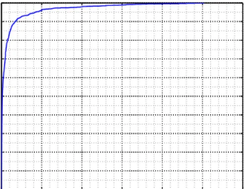
We downloaded the information of the nodes from the Tor network on Feb 8, 2010. There were 1513 onion routers in the Tor network. Figure 2 shows the empirical cumulative probability function. The maximum bandwidth in Tor network at that time is around5M B/s. The bandwidth of 90%of onion routers are less than350KB/s.
In scheme 1, by applying Algorithm 3, we can de-rive the probability P, denoted as catch probability, that a circuit chooses the sentinel onion routers as entry and exit onion routers. Figure 3 shows P given p ∈ {2%,4%,6%,8%,10%}, the percentage of EC2 sentinels within Tor, that is, we need {34,67,101,134,168} EC2 nodes, respectively. Then we select the maximum P and
0 1 2 3 4 5 6 0 0.1 0.2 0.3 0.4 0.5 0.6 0.7 0.8 0.9 1 Bandwidth (MB/s) F(x)
Figure 2. Empirical Cumulative PDF
0 20 40 60 80 100 120 140 160 180 0 0.1 0.2 0.3 0.4 0.5 0.6 0.7 0.8 0.9
Number of Exit Sentinels
Catch Probability
2% 4% 6% 8% 10%
Figure 3. Percentage of sentinels increasing to 10%
find the corresponding number of exit sentinels and entry sentinels as shown in Figure 4.
Figure 5 shows that with the increasing number of EC2 sentinels, catch probability increases in an exponential fashion. The curve’s slope is sharp when the number of EC2 sentinels is small. In Scheme 1, by deploying only 10%(168/(168+1513)) sentinel onion routers, i.e.,168EC2 sentinels including 61 exit routers and 107 entry routers shown in Figure 4, we can achieve catch probability of more than 80%. If the suspect makes 3 connections, law enforcement has over a probability of 99% (1−(1−80%)3) to determine the suspect.
34 67 101 134 168 0 20 40 60 80 100 120
Number of Total Sentinels
Number of Two Types of Sentinels
Exit Router Entry Router
In Scheme 2, we deploy all EC2 sentinels as EE onion routers. As shown in Figure 5, when we deploy 168 EC2 nodes, the probabilityP in Scheme 2 is almost equal to the results in scheme 1. In Scheme 3, we deploy the Amazon EC2 sentinels as exit onion routers, entry onion routers and EE onion routers. According to our investigation, when we derive the maximum probability P, the number of the EE onion routers is zero. Specifically, whenP reaches the maximum, Scheme 3 is the same as Scheme 1.
In addition, to increase the probability that a circuit chooses the EC2 sentinels as exit onion routers and entry onion routers, we should deploy the IP address range of the EC2 nodes in different class C and districts. Amazon EC2 can meet this requirement as we investigated in Section II.
20 40 60 80 100 120 140 160 180 0.35 0.4 0.45 0.5 0.55 0.6 0.65 0.7 0.75 0.8 0.85 Number of Sentinels Catch Probability Scheme 1 Scheme 2
Figure 5. Catch Probability vs. Number of Sentinels
V. CONCLUSION
In this paper, we propose to utilize the cloud computing for on-demand cyber crime scene investigations. In a time of intense crimes within anonymous communication networks such as Tor, law enforcement may purchase tens of Amazon EC2 VMs, which join the Tor network as sentinels. Those sentinels act as entry and exit nodes of Tor circuits and will be able to determine the attack sources within appro-priate traceback techniques. From our study, with 168 EC2 sentinels, we can achieve over 99% catch probability if the suspect makes 3 connections. As the traceback utilizes the “pay-as-you-go” model of cloud computing and the network forensics session may last for a few hours or a few days, the strategy is cost effective.
ACKNOWLEDGEMENT
We acknowledge anonymous reviewers for their incisive comments. This work is partially supported by NSF under grants 0943479, 0907964, and 0958477. Any opinions, findings and conclusions or recommendations expressed in this material are those of the authors and do not necessarily reflect the views of those sponsors.
REFERENCES
[1] “Introduction to cloud computing architecture, white paper by sun microsystems,” http://www.sun.com/featured-articles/ CloudComputing.pdf, June 2009.
[2] M. Armbrust, A. Fox, R. Griffith, A. D. Joseph, R. H. Katz, A. Konwinski, G. Lee, D. A. Patterson, A. Rabkin, I. Stoica, and M. Zaharia, “Above the clouds: A berkeley view of cloud computing,” Electrical Engineering and Computer Sciences University of California at Berkeley, Tech. Rep., February 2009.
[3] “Amazon.com: Amazon elastic compute cloud (Amazon EC2),” http://aws.amazon.com/ec2/, 2010.
[4] “Google App Engine,” http://code.google.com/appengine/, 2010.
[5] “Windows Azure Platform,” http://www.microsoft.com/ windowsazure/, 2010.
[6] “Introducing the windows azure platform,” http://www. microsoft.com/windowsazure/, December 2009.
[7] R. Dingledine, N. Mathewson, and P. Syverson, “Tor: The second-generation onion router,” inProceedings of the 13th USENIX Security Symposium, August 2004.
[8] ——, “Tor: anonymity online,” http://tor.eff.org/index.html. en, 2010.
[9] “Anonymizer,” http://www.anonymizer.com/, 2010.
[10] “I2P anonymous network,” http://www.i2p2.de/, 2010.
[11] “BitBlinder - protect your internet,” http://bitblinder.com/ learn/overview/, 2010.
[12] “AnoTorrent - anonymous p2p bittorrent,” http://www. anotorrent.net/, 2010.
[13] The Trustees of Princeton University, “Planetlab — an open platform for developing, deploying, and accessing planetary-scale services,” http://www.planet-lab.org/, 2010.
[14] Z. Ling, J. Luo, W. Yu, X. Fu, D. Xuan, and W. Jia, “A new cell counter based attack against tor,” inProceedings of 16th ACM Conference on Computer and Communications Security (CCS), 2009.
[15] R. Pries, W. Yu, X. Fu, and W. Zhao, “A new replay attack against anonymous communication networks,” inProceedings of the IEEE International Conference on Communications (ICC), May 19-23 2008.
[16] W. Yu, X. Fu, S. Graham, D. Xuan, and W. Zhao, “DSSS-based flow marking technique for invisible traceback,” in Proceedings of the 2007 IEEE Symposium on Security and Privacy (S&P), 2007 May.
[17] “Whois lookup and domain name search,” http://whois. domaintools.com/, 2010.
[18] “Announcement: Announcement: Amazon ec2 public ip ranges,” http://www.worldprivacyforum.org/pdf/WPF Cloud Privacy Report.pdf, December 2009.
[19] R. Dingledine and N. Mathewson, “Tor path specifi-cation,” http://gitweb.torproject.org/tor.git?a=blob plain;hb= HEAD;f=doc/spec/path-spec.txt, 2010.