D-Link Document – User Manual
D-Link Document - User Manual
DSN-6200/6500 Series
Version 1.00
December 2014
D-Link Document – User Manual
Copyright
Copyright@2014, D-Link Corporation, Inc. All rights reserved.
Trademarks
All products and trade names used in this manual are trademarks or registered trademarks of their respective companies.
Default login information
Management IP Address: 192.168.0.32 User name: admin
D-Link Document – User Manual
Preface
0
About This Manual
This manual introduces the D-Link storage system and it aims to help users know the operations of the disk array system easily. Information contained in this manual has been reviewed for accuracy, but not for product warranty because of the various environments / OS / settings. Information and specification will be changed without further notice.
Before reading this manual, it assumes that you are familiar with computer skills such as
hardware, storage concepts and network technology. It also assumes you have basic knowledge of Redundant Array of Independent Disks (RAID), Storage Area Network (SAN), Internet SCSI (iSCSI), Serial-attached SCSI (SAS), Serial ATA (SATA), technology.
CAUTION:
Do not attempt to service, change, disassemble or upgrade the equipment’s components by yourself. Doing so may violate your warranty and expose you
to electric shock. Refer all servicing to authorized service personnel. Please always follow the instructions in this user’s manual.
Tips and Cautions
This manual uses the following symbols to draw attention to important safety and operational information.
Symbol Meaning Description
TIP Tips provide helpful information, guidelines, or suggestions for performing tasks more effectively.
CAUTION Cautions indicate that failure to take a specified action could result in damage to the software or hardware.
D-Link Document – User Manual
Conventions Description
Bold Indicates text on a window, other than the window title, including menus, menu options, buttons, fields, and labels.
Example: Click OK button.
<Italic> Indicates a variable, which is a placeholder for actual text provided by the user or system.
Example: copy <source-file> <target-file>. [ ] square
brackets Example: [ a | b ] indicates that you can choose a, b, or nothing. Indicates optional values.
{ } braces Indicates required or expected values.
Example: { a | b } indicates that you must choose either a or b. | vertical bar Indicates that you have a choice between two or more options or
arguments.
/ Slash Indicates all options or arguments.
underline Indicates the default value.
D-Link Document – User Manual
Contents
Chapter 0 PREFACE ... 3
ABOUT THIS MANUAL ... 3
TIPS AND CAUTIONS ... 3
CONVENTIONS ... 3 Chapter 1 OVERVIEW ... 10 PRODUCT OVERVIEW ... 10 Model Comparison... 10 Package Contents ... 11 HARDWARE ... 11 Front View ... 12
Disk Drive Assembly ... 13
3TB / 6G MUX Board Limitation ... 14
Rear View ... 15 RAIDCONCEPTS ... 17 RAID Levels ... 18 Volume Relationship ... 18 ISCSICONCEPTS ... 19 SASCONCEPTS ... 20 Chapter 2 INSTALLATION ... 21 INSTALLATION OVERVIEW ... 21
Drive Slot Numbering ... 21
System Installation and Deployment ... 22
POWER ON/OFF ... 27
Power on the System ... 27
Power off the System ... 28
Chapter 3 QUICK SETUP... 29
MANAGEMENT INTERFACES ... 29
D-Link Document – User Manual
Web UI ... 32
HOW TO USE THE GUIDED CONFIGURATIONS ... 35
Quick Installation Tool ... 35
Volume Creation Wizard ... 40
Chapter 4 BASIC CONFIGURATION ... 44
INTERFACE HIERARCHY ... 44
SYSTEM CONFIGURATION ... 46
System Settings ... 47
Network Settings... 47
Login Settings ... 48
Email Notification Settings ... 49
Log and Alert Settings ... 50
HOST PORT / ISCSICONFIGURATION ... 52
Network Setup ... 52
Entity and iSCSI Settings ... 55
iSCSI Nodes ... 56 Active Sessions ... 58 CHAP Accounts ... 59 VOLUME CONFIGURATION ... 60 Physical Disks ... 61 RAID Groups ... 63 Virtual Disks ... 68 Snapshots ... 72 Logical Units ... 75 Replication ... 77 ENCLOSURE MANAGEMENT ... 78 Hardware Monitor ... 79 UPS ... 80 SES ... 81 S.M.A.R.T. ... 82 SYSTEM MAINTENANCE... 83 System Information ... 83 Event log ... 84 Upgrade ... 85
D-Link Document – User Manual
Volume Restoration ... 88
Reboot and Shutdown ... 89
PERFORMANCE MONITOR ... 90
Disk ... 90
iSCSI ... 90
Chapter 5 ADVANCED OPERATIONS ... 92
VOLUME REBUILD ... 92
MIGRATE AND MOVE RAIDGROUPS ... 93
EXTEND VIRTUAL DISKS ... 95
THIN PROVISIONING ... 96
The Benefits of Thin provisioning ... 97
Features Highlight ... 98
Thin Provisioning Options ... 100
Thin Provisioning Case ... 101
DISK ROAMING... 102 JBODEXPANSION... 102 Connecting JBOD ... 102 Upgrade Firmware ... 103 MPIO AND MC/S ... 104 MPIO ... 104 MC/S ... 104 Difference ... 105
TRUNKING AND LACP ... 105
LACP ... 106 Trunking ... 106 DUAL CONTROLLERS ... 107 Perform I/O ... 107 Ownership ... 108 Controller Status ... 108
Change Controller Mode ... 109
Recommend iSNS Server ... 109
SNAPSHOTS ... 110
Take a Snapshot ... 110
Cleanup Snapshots ... 111
D-Link Document – User Manual
CLONE ... 115
Setup Clone ... 115
Start and Stop Clone ... 116
Schedule Clone ... 116
Cloning Options ... 117
Clear Clone ... 118
Clone Constraint ... 118
REPLICATION ... 119
Create Replication Task ... 119
Start and Stop Replication Task ... 122
MPIO ... 122
MC/S ... 122
Task Shaping ... 123
Schedule Replication Task ... 124
Replications Options ... 125
Delete Replication Task ... 126
Clone Transfers to Replication ... 126
FAST REBUILD ... 129
Solution ... 129
Configuration ... 130
Constraint... 130
SSDCACHING (LICENSING FEE REQUIRED) ... 130
Solution ... 131
Methodology ... 131
Populating the Cache ... 132
Read/Write Cache Cases ... 132
I/O Type ... 134 Configuration ... 136 Constraints ... 137 Chapter 6 TROUBLESHOOTING ... 138 SYSTEM BUZZER ... 138 EVENT NOTIFICATIONS ... 138
Chapter 7 SOFTWARE APPLICATION ... 148
MICROSOFT ISCSIINITIATOR ... 148
D-Link Document – User Manual
Setup MC/S ... 149
Disconnect ... 150
Chapter 8 GLOSSARY AND ACRONYM LIST ... 151
D-Link Document – User Manual
Overview
1
Product Overview
This user manual describes how to set up and use the D-Link DSN-6200/6500 series storage systems.
The storage array, available in different configurations of, GbE iSCSI, 10GbE iSCSI and SAS interfaces, provides a flexible, intelligent, storage area network (SAN) solution for virtualized server environments and the glowing demand for data storage. D-Link storage systems can provide non-stop service with a high degree of fault tolerance by using D-link RAID technology and advanced array management features.
Model Comparison
D-Link storage system DSN-6200/6500 Series stands for the following models.
DSN-6200 Series: 6 x GbE iSCSI ports per controller. (DSN-6210: single controller, DSN-6220: dual-active controller).
D-Link Document – User Manual
Package Contents
The package contains the following items:
D-Link DSN-6200/DSN-6500 Series 1GbE/10GbE IP SAN STORAGE (x1) HDD trays (x12)
Power cords (x2)
RS-232 cables (x2), one is for console (black color, phone jack to DB9 female), and the other is for UPS (gray color, phone jack to DB9 male)
Rail kit (x1 set)
Keys, screws for drives and rail kit (x1 packet)
CD
Quick Installation Guide
Hardware
D-Link Document – User Manual
Front View
There is a power switch by the right front handle; a USB interface for a LCD screen by the left front handle.
Number Description
1 USB port:
This is designed specifically for USB LCD usage. It DOES NOT offer external USB storage function.
2 Access LED:
This indicates the host interface (frontend) connectivity, not the hard drive activity.
Blink: There is host interface activity (data I/O or management). OFF: There is no host interface activity.
3 Status LED:
Red: System failure. Off: System OK.
Number Description
1 Power button and power LED: Blue: Power ON. Off: Power OFF. 1
2
1 2
D-Link Document – User Manual
Management IP Address: 192.168.0.32 User Name: admin
Password: 123456
USB LCD comes as an optional device for the DSN-6200/6500 Series. The standard unit doesn’t include an USB LCD. Both the USB port on the front left handle and the USB port on the controller itself support the LCD function. However, the USB port doesn’t support external USB storage function.
Number Description
1 LCD display.
2 Up button.
3 Down button.
4 ENT (Enter) button.
5 ESC (Escape) button.
6 MUTE button.
7 USB connector
Disk Drive Assembly
Remove a drive tray. Then install a HDD.
To install SAS drives: align the edge of the drive to the back end of tray; the backplane can directly connect to the drives.
To install SATA drives with 3G/6G MUX boards: align the board edge to the back end of tray; the backplane can connect the drives through the boards.
1
2 3 4 5 6 7
D-Link Document – User Manual
SAS Drive SATA Drive
The front of each disk tray has four components:
This table below provides details about the front components of a disk tray.
Number Description
1 Power LED:
Green: Drive is inserted and operational. Red: Drive failure.
Off: No drive in the tray. 2 Access LED:
Blue blinking: The drive is being accessed.
Off: The drive is not being accessed or there is no drive in the tray.
3 Tray removal handle.
4 Latch to release the tray.
3TB / 6G MUX Board Limitation
DSN-6200/6500 Series:System JBOD
Single
upgradable Dual Single Dual
<= 2TB SATA No 6G MUX board No 6G MUX board > 2TB SATA No 6G MUX board No 6G MUX board
<= 2TB SAS No No No No
> 2TB SAS No No No No
1
2
D-Link Document – User Manual
SATA 6Gb/s SATA 6Gb/s SATA 3Gb/s SATA 3Gb/s SATA 6Gb/s SATA 3Gb/s SATA 1.5Gb/s SATA 6Gb/s SATA 1.5Gb/s
Without MUX Board SAS
3TB 2794 GB
SAS 6Gb/s SAS 6Gb/s
SAS 3Gb/s SAS 3Gb/s
Rear View
The following example shows the DSN-6220 chassis:
This table describes the rear modules.
Number Description
1 Controller 1 (CTRL 1).
2 Controller 2 (CTRL 2, only for dual-controller).
3 Fan Module (FAN1 / FAN2).
4 Fan Module (FAN3 / FAN4).
5 Power Supply Unit (PSU1).
6 Power Supply Unit (PSU2).
5 6 7 8 4 2 3 1 9 5 6 4 1 3 2
D-Link Document – User Manual
Number Description
1 SAN ports
DSN-6200: 6 x GbE iSCSI ports.
DSN-6500: 2 x 10GbE iSCSI ports (SFP+) + 2 x GbE iSCSI ports. 2 LEDs from right to left:
Controller health LED:
Green: Controller status normal.
Red: System booting or controller failure. Master slave LED (only for dual controllers): Green: This is the Master controller. Off: This is the Slave controller. Dirty cache LED:
Orange: Data on the cache waiting to flash to disks. Off: No data on the cache.
BBM LED (when status button pressed): Green: BBM installed and powered. Off: No BBM installed.
3 BBM status button (used to check the battery when the power is off.): If the BBM LED shows Green, then the BBM still has power to keep
data on the cache.
If the BBM LED stays Off, then the BBM power has run out and it cannot provide power for the cache anymore. It needs to be recharged or replaced.
4 Management port.
5 Console port.
6 RS 232 port for UPS.
7 SAS JBOD expansion port.
8 BBM slot.
9 USB
No function. Reserved for the future design purpose. LED 1GbE Link LED (All):
Orange: Asserted when a 1G link is established and maintained. Green: Asserted when a 100M link is establish and maintained. 1GbE Access LED (All):
Blinking green: Asserted when the link is established and packets are being transmitted along with any receive activity.
10GbE Link LED (DSN-6500):
Orange: Asserted when a 1G link is established and maintained. Blue: Asserted when a 10G link is establish and maintained. 10GbE Access LED (DSN-6500):
Yellow: Asserted when the link is established and packets are being transmitted along with any receive activity.
CAUTION:
Be aware that when Controller Health LED is in RED, please DO NOT unplug the controller from the system or turn off the power suddenly. This may
D-Link Document – User Manual
DSN-6200 (6 x GbE iSCSI) controller:
DSN-6500 (2 x 10GbE iSCSI (SFP+) + 2 x GbE iSCSI) controller:
DSN-6020 (6G SAS) JBOD controller:
RAID Concepts
RAID is the abbreviation of Redundant Array of Independent Disks. The basic idea of RAID is to combine multiple drives together to form one large logical drive. This RAID drive obtains performance, capacity and reliability than a single drive. The operating system detects the RAID drive as a single storage device.
2 7 7 5 6 2 3 4 7 1 9 5 6 2 3 4 7 1 9
D-Link Document – User Manual
RAID Levels
There are various RAID levels with different degrees of data protection, data availability, and performance. A description of supported RAID levels follow:
Type Description Min. No. of Drives
RAID 0 Disk striping. 1
RAID 1 Disk mirroring over two disks. 2 N-way
mirror Extension to RAID 1 level. It has N copies of the disk. N RAID 3 Striping with parity on the dedicated disk. 3 RAID 5 Striping with interspersed parity over the member
disks. 3
RAID 6 2-dimensional parity protection over the member
disks. 4
RAID 0+1 Mirroring of the member RAID 0 volumes. 4 RAID 10 Striping over the member RAID 1 volumes. 4 RAID 30 Striping over the member RAID 3 volumes. 6 RAID 50 Striping over the member RAID 5 volumes. 6 RAID 60 Striping over the member RAID 6 volumes. 8
JBOD The abbreviation of Just a Bunch Of Disks.
Independently address a drive. 1
Volume Relationship
The following graphic is the volume structure which D-Link has designed. It describes the relationship of RAID components.
RG PD 2 PD 3 DS PD 1 VD 1 VD 2 VD RAM Cache Volume +
LUN 1 LUN 2 LUN 3
+
D-Link Document – User Manual
One RG (RAID group) consists of a set of VDs (Virtual Disk) and owns one RAID level attribute. Each RG can be divided into several VDs. The VDs in one RG share the same RAID level, but may have different volume capacity. All VDs share the CV (Cache Volume) to execute the data transaction. LUN (Logical Unit Number) is a unique identifier, in which users can access through SCSI
commands.
iSCSI Concepts
iSCSI (Internet SCSI) is a protocol which encapsulates SCSI (Small Computer System Interface) commands and data in TCP/IP packets for linking storage devices with servers over common IP infrastructures. iSCSI provides high performance SANs over standard IP networks like LAN, WAN or the Internet.
IP SANs are true SANs (Storage Area Networks) which allow several servers to attach to an infinite number of storage volumes by using iSCSI over TCP/IP networks. IP SANs can scale the storage capacity with any type and brand of storage system. In addition, it can be used by any type of network (Ethernet, Fast Ethernet, Gigabit Ethernet, and 10 Gigabit Ethernet) and combination of operating systems (Microsoft Windows, Linux, Solaris, Mac, etc.) within the SAN network. IP-SANs also include mechanisms for security, data replication, multi-path and high availability.
Storage protocol, such as iSCSI, has “two ends” in the connection. These ends are initiator and target. In iSCSI, we call them iSCSI initiator and iSCSI target. The iSCSI initiator requests or initiates any iSCSI communication. It requests all SCSI operations like read or write. An initiator is usually
iSCSI device 1 (target) Host 1 (initiator) NIC IP SAN Host 2 (initiator) iSCSI HBA
D-Link Document – User Manual
The target is the storage device itself or an appliance which controls and serves volumes or virtual volumes. The target is the device which performs SCSI command or bridge to an attached storage device.
SAS Concepts
Serial-attached SCSI offers advantages over older parallel technologies. The cables are thinner, and the connectors are less bulky. Serial data transfer allows the use of longer cables than parallel data transfer.
The target is the storage device itself or an appliance which controls and serves volumes or virtual volumes. The target is the device which performs SCSI command or bridge to an attached storage device.
SAS device 1 (target) Host
(initiator) SAS HBA
D-Link Document – User Manual
Installation
2
Installation Overview
Before starting, prepare the following items:
A management computer with a Gigabit Ethernet NIC (recommend) on the same network as the D-Link storage system.
Connection cables:
。 Use CAT 5e, or CAT 6 (recommend) network cables for the management port. Prepare a storage system configuration plan. The plan should include network information
for the management port and iSCSI data ports. If using static IP addresses, please prepare a list of the static IP addresses, the subnet mask, and the default gateway.
Switches
。 DSN-6200: Gigabit switches (recommended) or Gigabit switches with VLAN / LCAP / Trunking (optional).
。 DSN-6500: Gigabit switches (recommended) or 10 Gigabit switches with VLAN / LCAP / Trunking (optional).
CHAP security information, including CHAP username and password (optional).
For dual-controller systems, it is recommended that the host logon to the target twice (both Controller 1 and Controller 2), and then the MPIO should setup automatically.
For an iSCSI dual-controller system, install an iSNS server on the same storage area network (recommended).
Drive Slot Numbering
The drives can be installed into any slot in the enclosure. Slot numbering is reflected in Web UI.
2U12:
Slot 1 Slot 4 Slot 7 Slot 10
D-Link Document – User Manual
TIP:
Install at least one drive in Slot 1 to 4 (marked gray slots). System event logs are saved in these drives. Otherwise, event logs no longer exist after a reboot.
System Installation and Deployment
Using the following instructions to install and deploy the storage system.
。 Install BBM (Battery Backup Module). The BBM module is located inside the right PSU (PSU2 module). Release the PSU2 latch and move to the back side.
。 Release the screws. Connect the BBM into the PSU. CAUTION:
Please do not touch the connector pins of the PSU when the BBM is connected.
。 Replace the cover on the PSU, and secure the bracket with screws. PSU2 Latch
D-Link Document – User Manual
。 Plug it into the chassis. 。 Install the Disk Drives.
。 Connect the management port cable and data port cables per the network plan, the topology examples for this are below.
D-Link Document – User Manual
DSN-6200 series (DSN-6220):
D-Link Document – User Manual
JBOD DSN-6020:
Dual controller topology:
For better data service availability, all the connections among hosts, switches, and the dual controllers are recommended to be redundant as shown below.
D-Link Document – User Manual
Console and UPS topology:
Connect the console cable and UPS per the following.
。 Using RS-232 cable for console (back color, phone jack to DB9 female), to connect from controller to management PC directly.
。 Using RS-232 cable for UPS (gray color, phone jack to DB9 male), to connect from controller to APC Smart UPS serial cable (DB9 female side), and then connect the serial cable to APC Smart UPS.
D-Link Document – User Manual
。 Attach the power cords and power on the system, and then power on the hosts and the iSNS server (optional for iSCSI environment).
。 Start the configuration.
Power ON / OFF
Power on the System
The power button is located at the right front handle. To turn on the system, you may press the power button once. After you turn the power ON, the system performs a booting process which takes a few minutes.
CAUTION:
Be aware that when Controller Health LED is in RED, please DO NOT unplug the controller from the system or turn off the power suddenly. This may
D-Link Document – User Manual
Power off the System
If it becomes necessary to power down the system, it is recommended using a normal, controlled shutdown form through either the LCD or Web UI to ensure all data is flushed from the cache first. 1. Shutdown using LCD:
On the LCD:
Power off the system using a normal shutdown. 。 Press ENT button.
。 Press (down) twice to show Reboot/Shutdown, and press ENT button. 。 Press (down) once to show Shutdown, and press ENT button.
。 Press (up) once to highlight Yes, and press ENT button.
System shutdown begins. When shutdown process completes, the power LED will turn off.
2. Shutdown using Web UI: Using the Web UI:
Select System Maintenance -> Reboot and Shutdown. Click the Shutdown icon.
System shutdown begins. When shutdown process completes, the power LED will turn off.
3. Shutdown using Power button:
The power button is located by the right front handle.
Forced shutdown: press and hold for more than 4 seconds. The power will be cut off immediately.
Graceful shutdown: press once to initialize graceful shutdown. Press a second time within 4 seconds to confirm and start graceful shutdown. If there is no 2nd press within 4 seconds, disable graceful shutdown and return to normal operating mode.
D-Link Document – User Manual
Quick Setup
3
Management Interfaces
There are several management methods to manage the storage system, described on the following pages.
Serial Console
Use console cable (NULL modem cable) to connect the console port of the storage system to RS 232 port of the management PC. The console settings are on the following:
Baud rate: 115200, 8 data bit, no parity, 1 stop bit, and no flow control. Terminal Type: vt100
The initial defaults for administrator login are: User Name: admin
Password: 123456
Secure Shell Remote Access
SSH (secure shell) software is required for remote login. The SSH client software is available on the following web sites:
SSH Tectia Client: http://www.ssh.com/ PuTTY: http://www.chiark.greenend.org.uk/
The default management IP address is 192.168.0.32/255.255.255.0, please configure your computer IP address at the same subnet of the system (e.g.: 192.168.1.234/255.255.255.0). The remote control settings are on the following:
Host IP: <IP Address> (e.g.: 192.168.0.32) User Name: admin
D-Link Document – User Manual
TIP:
D-Link systems support SSH for remote access only. When using SSH, the IP address and password are required for login.
LCD
After booting up the system, the following screen shows management port IP and model name. For example:
To access the LCD options, use the ENT (Enter) button, ESC (Escape) button, (up) and (down) to scroll through the functions.
This table describes the function of each item.
Function Description
System Info. Display system information including firmware version and amount of RAM.
Alarm Mute Mutes an alarm after an error occurs. Reset/Shutdown Reset or shutdown the system.
Quick Install Provide quick steps to create a volume. Volume Wizard Provide smart steps to create a volume. View IP Setting Display current IP address, subnet mask, and gateway. Change IP config Set IP address, subnet mask, and gateway. There are 2 options: DHCP
(Get IP address from DHCP server) or static IP.
Enc. Management Shows the enclosure data for physical disk temperatures, fan status, and power supply status.
Reset to Default Reset the system to default settings. The default resets include: Management IP Address: 192.168.0.32
User Name: admin Password: 123456
WARNING or ERROR events displayed on the LCD are automatically filtered by the LCD default filter. The filter setting can be changed in the Web UI under System Configuration -> Log and Alert Settings.
192.168.008.174 D-Link DSN-6500
D-Link Document – User Manual
This table displays the LCD menu hierarchy.
Main L1 L2 L3 L4 L5 <IP Addr> <Model> System Info. Firmware Version <n.n.n> RAM Size <nnnn> MB Alarm Mute Yes No
Reset/ Shutdown Reset NoYes Shutdown NoYes Quick Install (only available if not already set) <RAID 0 RAID 1 RAID 3 RAID 5 RAID 6 RAID 0+1> nnn GB Apply The Config NoYes Volume Wizard (only available if not already set) Local <RAID 0 RAID 1 RAID 3 RAID 5 RAID 6 RAID 0+1> Use default
algorithm Volume Size <nnn> GB
Apply The Config Yes No JBOD <n> <RAID 0 RAID 1 RAID 3 RAID 5 RAID 6 RAID 0+1> New n disk <nnn> GB Adjust Volume Size Apply The Config Yes No View IP Setting IP Config <Static IP / DHCP / BOOTP> IP Address <192.168.001.234 > IP Subnet Mask <255.255.255.0> IP Gateway <xxx.xxx.xxx.xxx> Change IP Config DHCP NoYes BOOTP NoYes Static IP
IP Address Adjust IP address IP Subnet Adjust
D-Link Document – User Manual
Apply IP
Setting Yes No
Enc. Management
Phy. Disk Temp. Slot <Local n>: <nn> (C) Cooling Local FAN<n>: <nnnnn> RPM Power Supply PSU<Local n>:
<status> Reset to
Default Yes No
The USB LCD was developed to add more mobility and flexibility during deployment and
installation. In order to save costs, several DSN-6200/6500 systems can share one USB LCD. All the functions provided by USB LCD are the same as the original LCD introduced in the previous section. Please be aware to remove the USB LCD before adding the front bezel.
CAUTION:
To prevent data loss, when powering down the storage system, it is recommended to execute Reset/Shutdown -> Shutdown -> Yes to flush the
data from the cache to the physical disks.
Web UI
D-Link storage systems support graphic user interface operation. They support most common web browsers. Be sure to connect the LAN cable to the management port of the system.
The default management IP address is 192.168.0.32/255.255.255.0, please configure your computer IP address at the same subnet of the system (e.g.: 192.168.1.234/255.255.255.0). And
D-Link Document – User Manual
To access the Web UI, you have to enter a user name and password. The initial defaults for administrator login are:
User Name: admin Password: 123456
Choose the functions from the Menu Bar on the left side of the window to make any configuration changes. Menu Bar Options Indicators and Icons Operation Area
D-Link Document – User Manual
TIP:
The Host Port Configuration menu bar option is only visible when the controller has multiple interfaces. The iSCSI Configuration menu bar option is
only visible when the controller has iSCSI ports.
There are up to seven indicators and three icons at the top-right corner. The last indicator (Dual controller) is only visible when two controllers are installed.
Icon Description
RAID indicator:
Green: All RAID groups are functioning. Red: A RAID group is degraded or has failed.
Temperature indicator: Green: Temperature is normal.
Red: Temperature is too high. Voltage indicator:
Green: Voltage values are normal. Red: Voltage values are out of range.
UPS indicator:
Green: UPS is functioning or no UPS is connected. Red: UPS connection has failed.
Fan indicator:
Green: Fan is working well. Red: Fan failed.
Power indicator:
Green: Power supplies are connected and working well. Red: A power supply has failed or is no longer connected.
Dual controller indicator:
Green: Dual controllers are active and working well. Orange: One of the dual controllers has failed.
Return to home page. Logout of the management web UI.
Mute alarm beeper. This table describes the indicators and icons.
TIP:
If the status indicators in Internet Explorer (IE) are displayed in gray, not in blinking red, please enable Tools -> Internet Options -> Advanced -> Play animations in webpages options in IE. The default value is enabled, but some
D-Link Document – User Manual
How to Use the Guided Configurations
To help users get started quickly, two guided configuration tools are available in the Web UI and LCD. Quick Installation gives you an easy way to create a volume. Volume Creation Wizard provides a smarter policy to help users to create a volume. If you are an advanced user, you can skip these steps.
Quick Installation Tool
This tool guides you through the process of setting up basic array information, configuring network settings, and the creation of a volume on the storage system. Please make sure that you have some free hard drives installed on the system. SAS drivers are recommended.
1. Click Quick Installation from the menu bar.
D-Link Document – User Manual
3. Confirm or change the management port IP address and DNS server. If the default HTTP, HTTPS, and SSH port numbers are not allowed on your network, they can be changed here as well.
D-Link Document – User Manual
4. For iSCSI Configurations, use this step to set up the data port iSCSI IP address, and then click the Next button.
D-Link Document – User Manual
5. Choose a RAID Level. The number in the brackets is the maximum capacity at the RAID level. This step utilizes all drives in the storage system as well as any JBOD expansion arrays present. This option allows the selection of the RAID type and the number of drives in each array.
D-Link Document – User Manual
D-Link Document – User Manual
The iSCSI information is only displayed when iSCSI controllers are used. Use the Back button to return to a previous page to change any setting.
Volume Creation Wizard
The Volume Creation Wizard provides a smarter policy to determine all possibilities and volume sizes in the different RAID levels that can be created using the existing free drives. It provides: Largest capacity for each RAID level from which to choose.
The fewest number of drives for each RAID level / volume size.
This way, after choosing a RAID level, you may find that some drives are still available (free status). This phenomenon is the result of using smart design. For example, a user chooses the RAID 5 level and the system has 12*200GB + 4*80GB free drives inserted. Generally, if using all 16 drives for a RAID 5 group, the maximum size of volume is (16-1)*80GB = 1200GB. This wizard provides a smarter check and searches the most efficient way of using free drives. It uses 200GB drives only to provide (12-1)*200GB = 2200GB capacity, as a result the volume size is larger using less drives. 1. Click Volume Creation Wizard from the menu bar.
D-Link Document – User Manual
3. Select the default option Maximize the size of the RAID group or manual option Select the number of disks to use. From the drop-down list, select either the RAID Group capacity combination desired. Click Next button to proceed.
4. Enter the Volume Size (GB) desired that is less than or equal to the default available size shown. Then click Next button.
D-Link Document – User Manual
5. Use LBA 64 support? It depends on the operation system.
D-Link Document – User Manual
D-Link Document – User Manual
Basic Configuration
4
Interface Hierarchy
This table describes the hierarchy of the web GUI.
Menu Bar L1 L2, Button or Menu
System
Configuration Network Settings System Settings System Name / Date and Time / System Indication MAC Address / IP Address / DNS Server Address / Service Ports
Login Settings Login Options / Admin Password / User Password Email Notification
Settings Email Settings / Send Test Mail Log and Alert
Settings Server Settings / Admin Interface and Front Display SNMP Trap Settings / Windows Messenger / Syslog Alerts / Device Buzzer
iSCSI Configuration (This option is only visible when the controller has iSCSI ports.) Host Configuration (This option is only visible when the controller has multiple interfaces.)
Network Setup Show information for: < Controller 1 | Controller 2 > Options: [iSCSI Bonding Settings | Delete iSCSI Bonding] / Set VLAN ID / iSCSI IP Address Settings /
Make Default Gateway / [Enable | Disable] Jumbo Frames / Ping Host / Reset Port
Entity and iSNS
Settings Entity Name / iSNS IP Address
iSCSI Node Show information for: < Controller 1 | Controller 2 > Options: Authentication Method / Change Portal /
Rename Alias / Users
Active Sessions Show information for: < Controller 1 | Controller 2 > Connection Details / Disconnect
CHAP Accounts Create User
Options: Modify User Information / Delete User
Volume
Configuration Physical Disks Show disk for: < -Local- | -JBODn- > Show disk size in: < (GB) | (MB) > Disk Health Check / Disk Check Report Options: Set Free Disk / Set Global Spare / Set Local Spare / Set Dedicated Spare / Upgrade / Disk Scrub / Read Error Cleared / Turn [on | off] the Indication LED
/ More information RAID Groups Show RAID size in: < (GB) | (MB) >
D-Link Document – User Manual
Options: Migrate RAID Level / Move RAID Level / Activate / Deactivate / Verify Parity / Delete / Change Preferred Controller / Change RAID Options / Add RAID
Set / Add Policy / More information RAID Set options: Remove / Move RAID Level / List
Disks
RAID Group Policy options: Delete / Modify Virtual Disks Create / Cloning Options
Options: Extend / Set SSD Caching / Verify Parity / Delete / Set Properties / Space Reclamation / Attach
LUN / Detach LUNs / List LUNs / Set Clone / Set Snapshot Space / Cleanup Snapshots / Take a Snapshot
/ Scheduled Snapshots / List Snapshots / More information
Snapshots Set Snapshot Space / Scheduled Snapshots / Take a Snapshot / Cleanup Snapshots
Options: Set Quota / Rollback / Delete Logical Units Attach LUN
Options: Detach LUN
Replication Create / Rebuild / Replication Options / Shaping Setting Configuration
Options: Start / Stop / Set Task Shaping / Add Path / Delete Path / Schedule / Delete / Add Connection /
Delete Connection Enclosure
Management Hardware Monitor Show information for: < -Local- | -JBODn- > Temperature (Internal)/(Case): < (C) / (F) > Controller 1 Monitors / Controller 2 Monitors /
Backplane Options: Auto Shutdown
UPS UPS Type / Shutdown Battery Level (%) / Shutdown Delay (Seconds) / Shutdown UPS / UPS Status / UPS
Battery Level
SES [Enable | Disable]
S.M.A.R.T. Show information for: < -Local- | -JBODn- > Temperature (Internal)/(Case): < (C) / (F) > System
Maintenance information System Download System Information
Event log Event Log Level to Show: < Information | Warning | Error >
Download / Mute Buzzer / Clear
Upgrade Controller Module Firmware Update / JBOD Firmware Update / Controller Mode
Firmware Synchronization
(This option is only visible when
dual controllers are inserted.) Apply Reset to Factory Default Reset Configuration
D-Link Document – User Manual
Reboot and
Shutdown Reboot options: Both Controller 1 and Controller 2 / Reboot / Shutdown Controller 1 / Controller 2
Performance
Monitor iSCSI Disk Show disk for: < -Local- | -JBODn- > Controller 1 / Controller 2 Quick
Installation Step 1 / Step 2 / Step 3 / Step 4 / Confirm Volume
Creation Wizard
Step 1 / Step 2 / Step 3 / Confirm
System Configuration
The System Configuration menu option is for accessing the System Settings, Network Settings, Login Settings, Email Notification Settings, and Log and Alert Settings option tabs.
D-Link Document – User Manual
System Settings
The System Settings tab is used to setup the system name and date.
The options available on this tab are:
System Name: Change the System Name, highlight the old name and type in a new one. Date and Time: To change the current date, time and time zone settings, check Change Date
and Time. The changes can be done manually or synchronized from an NTP (Network Time Protocol) server.
System Identification: To Flash the status light on the front display for locating this system in the racks, click OK button. To stop Flash the status light on the front display, click the OK button again.
When it is done, click the Apply button.
Network Settings
D-Link Document – User Manual
The options available on this tab are:
Enable dual management ports: This is for dual controller models. Check it to enable dual management ports.
MAC Address: Display the MAC address of the management port in the system.
IP Address: The option can change IP address for remote administration usage. There are three options: DHCP, BOOTP, and Specify a Static IP Address. The default setting is DHCP. DNS Server Address: If necessary, the IP address of DNS server can be entered or changed
here.
Service Ports: If the default port numbers of HTTP, HTTPS, and SSH are not allowed on the network, they can be changed here.
When it is done, click the Apply button.
Login Settings
D-Link Document – User Manual
The options available on this tab are:
Auto Logout: When the auto logout option is enabled, you will be logged out of the admin interface after the time specified. The options available are: Disable (default), 5 minutes, 30 minutes and 1 hour options.
Login Lock: When the login lock is enabled, the system allows only one user to login to the web UI at a time. There are Disable (default) and Enable options.
Change Admin Password: Check it to change administrator password. The maximum length of password is 12 alphanumeric characters.
Change User Password: Check it to change user password. The maximum length of password is 12 alphanumeric characters.
When it is done, click the Apply button.
Email Notification Settings
The Email Notification Settings tab is used to enter up to three email addresses for receiving the event notifications. Fill in the necessary fields and click Send Test Email button to test whether it is available. Some email servers will check the mail-from address and need the SMTP relay settings for authentication.
D-Link Document – User Manual
You can also select which levels of event logs that you would like to receive. The default setting only includes Warning and Error event logs.
When it is done, click the Apply button.
Log and Alert Settings
The Log and Alert Settings tab is used to setup SNMP traps (for alerting via SNMP), pop-up messages via Windows messenger (not MSN or Skype), alerts via the syslog protocol, the pop-up alerts, and alerts on the front display. The device buzzer is also managed here.
D-Link Document – User Manual
The options available on this tab are:
SNMP Trap Settings: It allows up to three SNMP trap addresses. The default community setting is public. You can check the alert levels that you would like to receive. The default setting only includes Warning and Error event logs. If necessary, click Download to get the MIB file for importing to the SNMP client tool.
There are many SNMP tools available on the internet. 。 SNMPc: http://www.snmpc.com/
。 Net-SNMP: http://net-snmp.sourceforge.net/
Windows Messenger: You must enable the Messenger service in Windows (Start -> Control Panel -> Administrative Tools -> Services -> Messenger). It allows up to three host
addresses. You can also check the alert levels for receiving emails here.
System Server Settings: Fill in the host address and the facility for syslog service. The default UDP port is 514. You can also check the alert levels here.
D-Link Document – User Manual
Most UNIX systems build in syslog daemon.
Admin Interface and Front Display Alerts: You can check the alert level that will activate a pop-up message in the Web UI or on the front display.
Device Buzzer: Check it to disable the device buzzer. Uncheck it to activate the device buzzer.
When it is done, click the Apply button.
Host Port / iSCSI Configuration
The Host port / iSCSI Configuration menu option is for accessing the Network Setup, Entity and iSNS Settings, iSCSI Nodes, Active Sessions, CHAP Account.
Network Setup
The Network Setup tab is used to change IP addresses of iSCSI data ports. The two controllers have different iSCSI ports, listed below:
DSN-6200/6500 Series:
DSN-6200: 6 x GbE iSCSI ports per controller.
DSN-6500: 2 x 10GbE iSCSI ports + 2 x GbE iSCSI ports per controller.
These network ports must be assigned IP addresses before they can be used. For better performance or fault tolerance reason, they can be set as Trunking or LACP. These bonding network ports share a single IP address. The following example shows the DSN-6200 Series (DSN-6210: 6 x GbE iSCSI ports).
D-Link Document – User Manual
This figure shows six iSCSI data ports. These data ports are set up with a static IP address. For the other controllers, they can be set up the same way.
The options available on this tab:
▼ iSCSI Bonding Settings: The default mode of each iSCSI data port is for it to be
individually connected without any bonding. Trunking and LACP (Link Aggregation Control Protocol) settings can be setup here. At least two iSCSI data ports must be checked for iSCSI bonding.
。 Trunking: Configures multiple iSCSI ports to be grouped together into one in order to increase the connection speed beyond the limit of a single iSCSI port.
。 LACP: The Link Aggregation Control Protocol is part of IEEE specification 802.3ad that allows bonding of several physical ports together to form a single logical channel. LACP allows a network switch to negotiate an automatic bundle by sending LACP packets to the peer. The advantages of LACP are that it increases bandwidth usage and it automatically performs a failover when the link status fails on a port.
▼ Set VLAN ID: VLAN is a logical grouping mechanism implemented on switch device.
VLANs are collections of switching ports that comprise a single broadcast domain. It allows network traffic to flow more efficiently within these logical subgroups. Please consult your network switch user manual for VLAN setting instructions. Most of the work is done at the switch part. All you need to do is to make sure that your iSCSI port's VLAN ID matches that of switch port. If your network environment supports VLAN, you can use this function to change the configurations. Fill in VLAN ID and Priority settings to enable VLAN.
D-Link Document – User Manual
。 VLAN ID: VLAN ID is a 12-bit number. Its range is from 2 to 4094, while 0, 1, and 4095 are reserved for special purposes.
。 Priority: The PCP (Priority Code Point) is a 3-bit number and reserved for QoS. The definition complies with IEEE 802.1p protocol, ranging from 0 to 7, with 0 as the default value. In normal cases, you don't need to set this value. Using the default will do just fine.
TIP:
If iSCSI ports are assigned with VLAN ID before creating aggregation takes place, aggregation will remove VLAN ID. You need to repeat the steps to set
VLAN ID for the aggregation group.
▼ iSCSI IP Address Settings: It can assign an iSCSI IP address of the iSCSI data port. There are two options: Use DHCP to acquire an IP address automatically or Specify a Static IP Address to set the IP address manually.
▼ Make Default Gateway: Set the gateway of the IP address as default gateway. There
can be only one default gateway. To remove the default gateway, click ▼ Remove Default Gateway.
D-Link Document – User Manual
CAUTION:
VLAN ID, jumbo frames for both the switching hub and HBA on host must be enabled. Otherwise, the LAN connection cannot work properly.
▼ Ping host: It can verify the port connection from a target to the corresponding host
data port. Input the host’s IP address and click the Start button. The system will display the ping result. Or click the Stop button to stop the test.
▼ Reset Port: If the behavior of the port is abnormal, try to reset the port to make it
normal.
Entity and iSCSI Settings
The Entity and iSCSI Settings tab is used to view the entity name of the system, and setup iSNS IP for the iSNS (Internet Storage Name Service) protocol. It allows automated discovery, management and configuration of iSCSI devices on a TCP/IP network. To use iSNS, an iSNS server needs to be added to the SAN. When this is done, the iSNS server IP address must be added to the storage system for iSCSI initiator service to send queries to it.
D-Link Document – User Manual
iSCSI Nodes
The iSCSI Nodes tab is used to view the target name for iSCSI initiator. The two controllers support multiple nodes, listed below.
DSN-6200 Series: support up to 64 multiple nodes per controller. DSN-6500 Series: support up to 64 multiple nodes per controller.
The options available on this tab are:
▼ Authentication Method: CHAP (Challenge Handshake Authentication Protocol) is a
strong authentication method used for user login. It’s a type of authentication in which the authentication server sends the client a key to be used for encrypting the username and password. CHAP enables the username and password to transmit in an encrypted form for protection.
TIP:
A CHAP account must be added before you can use this authentication method. Please refer to CHAP Accounts section to create an account if none exists.
To use CHAP authentication, please follow the procedures. 。 Select one of the nodes from one controller. 。 Check ▼ Authentication Method. 。 Select CHAP from the drop-down list.
D-Link Document – User Manual
。 Click the OK button.
。 Check ▼ User.
。 Select the CHAP user(s) that will have access to the node. It can be more than one, but there must be at least one user to enable chap protection on the node.
。 Click the OK button.
To disable CHAP authentication, please follow the procedure below. 。 Select the node on which you want to disable CHAP. 。 Check ▼ Authentication Method.
。 Change it to None from the drop-down list. 。 Click the OK button.
▼ Change Portal: Use this iSCSI node option to change the network ports available.
。 Select one of the nodes from one controller. Check Change Portal.
D-Link Document – User Manual
。 Click OK button.
▼ Rename Alias: Use this option to add or change iSCSI alias.
。 Select one of the nodes from one controller. 。 Check ▼ Rename Alias.
。 Enter the Alias Name. Leave it empty to remove the alias. 。 Click the OK button.
TIP:
After setting CHAP, the host initiator should be set with the same CHAP account. Otherwise, the host cannot connect to the volume.
Active Sessions
D-Link Document – User Manual
This table shows the column descriptions. Most of the options are standard parameters used in the negotiation between the initiator and the target when an iSCSI connection is created.
Column Name Description
TSIH TSIH (Target Session Identifying Handle) is used for this active session. Initiator Name It displays the host computer name.
Target Name It displays the controller name.
InitialR2T InitialR2T (Initial Ready to Transfer) is used to turn off either the use of a unidirectional R2T command or the output part of a bidirectional
command. The default value is Yes.
Immed. data Immed. data (Immediate Data) sets the support for immediate data between the initiator and the target. Both must be set to the same
setting. The default value is Yes.
MaxDataOutR2T MaxDataOutR2T (Maximum Data Outstanding Ready to Transfer) determines the maximum number of Outstanding Ready to Transfer
per task. The default value is 1.
MaxDataBurstLen MaxDataBurstLen (Maximum Data Burst Length) determines the maximum SCSI data payload. The default value is 256kb. DataSeginOrder DataSeginOrder (Data Sequence in Order) determines if the PDU
(Protocol Data Units) are transferred in continuously non-decreasing sequence offsets. The default value is Yes.
DataPDU InOrder DataPDU InOrder (Data PDU in Order) determines if the data PDUs within sequences are to be in order and overlays forbidden. The
default value is Yes. The options available on this tab are:
▼ Connection Details: It can list all connection(s) of the selected session.
▼ Disconnect: Disconnect the selected session, click the OK button to confirm.
CHAP Accounts
D-Link Document – User Manual
Create User: Create a CHAP user.
。 Enter the required information for User Name, Secret, and Re-type Secret. 。 If you would like this CHAP user to have access, select one or multiple nodes. If
selecting none, you can add it later by iSCSI Configuration iSCSI Nodes Users. 。 Click OK button.
▼ Modify User Information: Modify the selected CHAP user information.
▼ Delete User: Delete the selected CHAP user.
Volume Configuration
The Volume configuration menu option is for accessing the Physical Disks, RAID Groups, Virtual Disks, Snapshots, Logical Units, and Replications option tabs.
D-Link Document – User Manual
Physical Disks
The Physical Disks tab provides the status of the hard drives in the system. The two drop-down lists at the top enable you to switch between the local system and any expansion JBOD systems attached. The other is to change the drive size units (MB or GB).
This table shows the column descriptions.
Column Name Description
Slot The position of a hard drive. The button next to the slot number shows the functions that can be executed.
Size (GB) or (MB) Capacity of hard drive. The unit can be displayed in GB or MB.
RAID Group RAID group name.
RAID Set The number of RAID Set:
N/A: The RAID group is traditional provisioning. Number: The RAID group is the number of RAID set to thin
provisioning. Virtual Disk Virtual disk name for SSD caching.
Status The status of the hard drive: Online: The hard drive is online. Rebuilding: The hard drive is being rebuilt.
Transitioning: The hard drive is being migrated or is replaced by another disk when rebuilding occurs.
Scrubbing: The hard drive is being scrubbed. Health The health of the hard drive:
Good: The hard drive is good. Failed: The hard drive has failed. Error Alert: S.M.A.R.T. error alerts.
Read Errors: The hard drive has unrecoverable read errors. Usage The usage of the hard drive:
RAID: This hard drive has been set to a RAID group. Free: This hard drive is free for use.
Dedicated Spare: This hard drive has been set as a dedicated spare of a RAID group.
Local Spare: This hard drive has been set as local spare of the enclosure.
D-Link Document – User Manual
Serial Number Hard drive serial number.
Rate Hard drive rate:
SAS 6.0Gb/s. SAS 3.0Gb/s. SATA 6.0Gb/s. SATA 3.0Gb/s. SATA 1.5Gb/s. SAS SSD 6.0Gb/s. SATA SSD 6.0Gb/s.
Write Cache Hard drive write cache is enabled or disabled. The default value is Enabled.
Standby HDD auto spin down to save power. The default value is Disabled. Read-Ahead This feature ensures data is loaded to disk’s buffer in advance for further
use. The default value is Enabled. Command
Queuing Newer SATA and most SCSI disks can queue multiple commands and handle each command individually. The default value is Enabled. The options available on this tab are:
Disk Health Check: Check the health of the selected disks. It cannot check the disks currently in use.
Disk Check Report: Download the disk check report. It’s available after executing Disk Health Check.
▼ Set Free Disk: Make the selected hard drive free for use.
▼ Set Global Spare: Set the selected hard drive to global spare for all RAID groups.
▼ Set Local Spare: Set the selected hard drive to a local spare for the RAID groups
located in the same enclosure.
▼ Set Dedicated Spare: Set a hard drive to a dedicated spare of the selected RAID group.
▼ Upgrade: Upgrade the firmware of the hard drive.
▼ Disk Scrub: Scrub the hard drive. It’s not available when the hard drive is in use.
▼ Read Error Cleared: Clean the read error of the hard drive.
▼ Turn on/off the indication LED: Turn on the indication LED of the hard drive. Click it
again to turn off.
▼ More information: Display the hard drive details.
D-Link Document – User Manual
2. If there is any RAID group which is in protected RAID level and can be set with a dedicated spare disk, select one RAID group, and then click OK button.
TIP:
For DSN-6200/6500Series, the maximum number of physical drives in a system is 256.
RAID Groups
The RAID Groups tab is provided to create, modify, delete, or view the status of the RAID groups. Use the drop-down list at the top to change the drive size units (MB or GB).
Select the traditional RAID group, the following will be displayed.
This table shows the column descriptions.
Column Name Description
Name RAID group name.
Total (GB) or
(MB) Total capacity of the RAID group. The unit can be displayed in GB or MB. Free Capacity
(GB) or (MB) Free capacity of the RAID group. The unit can be displayed in GB or MB. Available Size
(GB) or (MB) Available capacity of the RAID group. The unit can be displayed in GB or MB. Thin Provisioning The status of Thin provisioning:
Disabled. Enabled.
Disks Uses The number of physical disks in the RAID group. Number of
D-Link Document – User Manual
Rebuilding: the RAID group is being rebuilt. Migrating: the RAID group is being migrated. Scrubbing: the RAID group is being scrubbed. Health The health of the RAID group:
Good: the RAID group’s health is good. Failed: the RAID group has failed.
Degraded: the RAID group is not healthy and not completed. The reason could be lack of disk(s) or a failed disk.
RAID The RAID level of the RAID group. Current
Controller (This option is only visible when
dual controllers are installed.)
The controller of the RAID group. The default is controller 1.
Preferred Controller (This option is only visible when
dual controllers are installed.)
The preferred controller of the RAID group. The default is controller 1.
The options available on this tab are: Create: Create a RAID group.
The options available after creating a RAID group are:
▼ Migrate RAID Level: Change the RAID level of a RAID group. Please refer to the next
chapter for details.
▼ Move RAID Level: Move the member disks of RAID group to totally different physical
disks.
▼ Activate/Deactivate: Activate or deactivate the RAID group after disk roaming.
Activate can be executed when the RAID group status is offline. Conversely, Deactivate can be executed when the status is online. These are for online disk roaming purpose.
▼ Verify Parity: Regenerate parity for the RAID group. It supports the RAID level 3 / 5 / 6
/ 30 / 50 / 60.
▼ Delete: Delete the RAID group.
▼ Change Preferred Controller: Set the RAID group ownership to the other controller.
▼ Change RAID Options: Change the RAID property options.
。 Write Cache:
Enabled: When the write cache is enabled, data transfer operations are written to fast cache memory instead of being written directly to disk. This may improve performance but will also increase the risk of losing data when losing power if
D-Link Document – User Manual
。 Standby:
Disabled: Disable auto spin down. (Default)
30 sec / 1 min / 5 min / 30 min: The hard drives will be spun down for power saving when the disk is idle for the period of time specified.
。 Read-Ahead:
Enabled: The system will discern what data will be needed next based on what was just retrieved form disk and then preload this data into the disks buffer. This feature will improve performance when the data being retrieved is sequential. (Default)
Disabled: Disable disk read ahead. 。 Command Queuing:
Enabled: Sends multiple commands at once to a disk to improve performance. (Default)
Disabled: Disable disk command queuing.
▼ Add RAID Set: Add RAID sets for the thin provisioning RAID group.
▼ Add Policy: Add policy for the thin provisioning RAID group.
▼ More information: Display RAID group’s information.
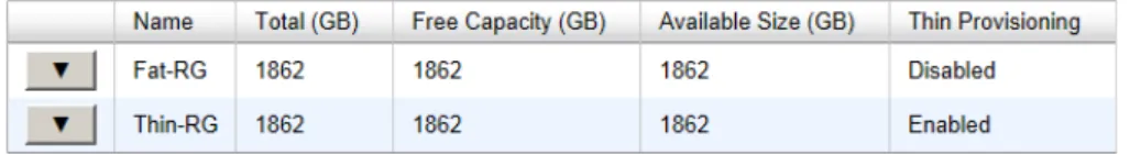
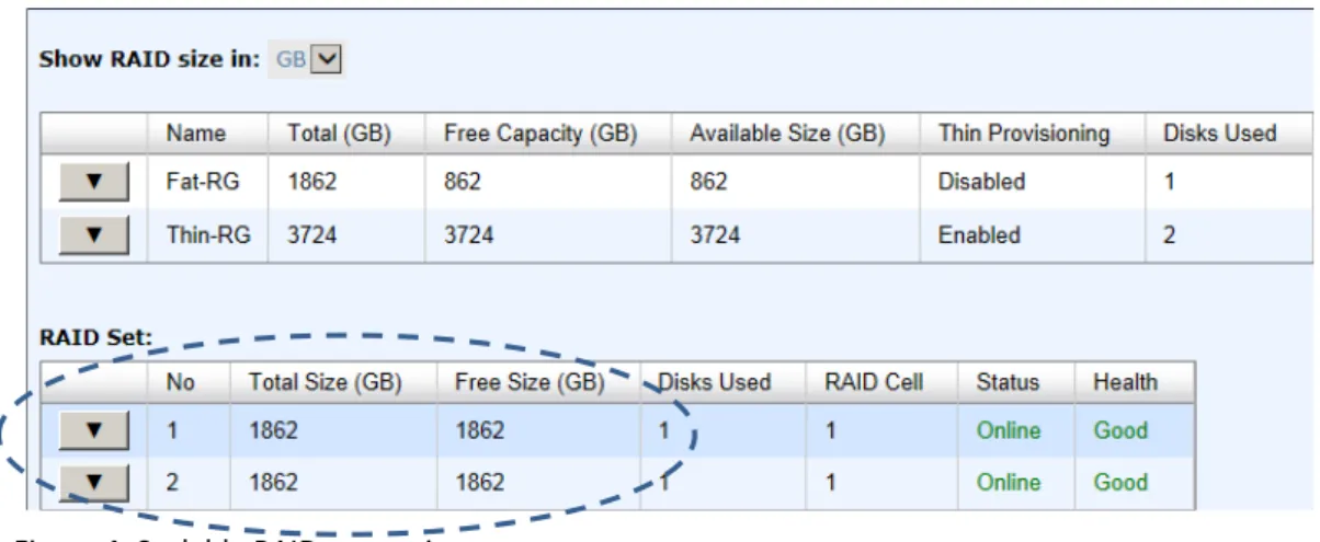
Select the thin provisioning RAID group, it will be displayed as below. There are two more tables to describe the properties of the thin provisioning RAID group, RAID Set and RAID Group Policy.
This table shows the column descriptions of RAID Set.
D-Link Document – User Manual
Disks Used The number of physical disks in the RAID set. RAID Cell The number of RAID cells in the RAID set.
Status The status of the RAID group: Online: the RAID group is online. Offline: the RAID group is offline. Rebuilding: the RAID group is being rebuilt. Migrate: the RAID group is being migrated. Scrubbing: the RAID group is being scrubbed. Health The health of the RAID group:
Good: the RAID group’s health is good. Failed: the RAID group has failed.
Degraded: the RAID group is not healthy and not completed. The reason for this could be lack of disk(s) or a disk has failed. The options available on this tab are:
▼ Remove: Remove the selected RAID set.
▼ Move RAID Level: Move the member disks of the RAID set to other physical disks.
▼ List Disks: Display all disks.
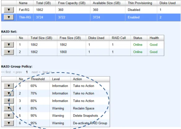
This table shows the column descriptions of RAID Group Policy.
Column Name Description
No The number of the RAID group policy. Threshold The threshold of the thin provision RAID group.
Level Define the event log level when the thin provision RAID group usage reaches the threshold.
Action Take action when the thin provision RAID group usage reaches the threshold.
Take no Action. Reclaim Space. Delete Snapshots. De-activate RAID Group. The options available on this tab are:
▼ Delete: Delete the selected policy.
▼ Modify: Modify the level and the action of the policy.
Take an example of creating a RAID group. 1. Click the Create button.
D-Link Document – User Manual
2. Enter a RAID Name for the RAID group. 3. Select a RAID Level from the drop-down list.
4. Click the Select Disks button to select disks from either local or expansion JBOD systems, and click OK to complete the selection. The selected disks are displayed at RAID Disks.
5. Optionally, configure the following:
。 Preferred Controller: This option is only visible when dual controllers are installed. The default value is Auto.
。 Thin Provisioning: This option is only visible when the thin provisioning feature is enabled. The default value is Disabled.
。 Write Cache: Enable or disable the write cache option of the hard drives. The default value is Disabled.
。 Standby: Enable or disable the auto spin down function of the hard drives. When this option is enabled and the hard drives have no I/O access after a certain period of time, they will spin down automatically. The default value is Disabled.
。 Read-Ahead: Enable or disable the read ahead function. The default value is Enabled. 。 Command Queuing: Enable or disable the hard drives’ command queue function. The
default value is Enabled.
6. At the confirmation dialog, click OK button to create the RAID group.
TIP:
For the DSN-6200/6500 Series the maximum number of physical drives in a RAID group is 64.
D-Link Document – User Manual
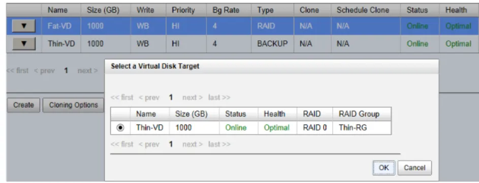
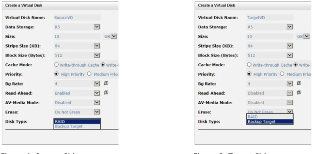
Virtual Disks
The Virtual Disks tab is provided to create, modify, delete, or view the status of the virtual disk. Use the drop-down list at the top to change the drive size units (MB or GB).
This table shows the column descriptions.
Column Name Description
Name Virtual disk name.
Size (GB) or (MB) Total capacity of the virtual disk. The unit can be displayed in GB or MB. SSD Caching The SSD caching policy:
Disable: Disable SSD caching.
Database: Enable SSD caching and set it as database policy. File System: Enable SSD caching and set it as file system policy. Web Service: Enable SSD caching and set it as web service policy.
Custom: Enable SSD caching and set it as customization policy. Write The right of virtual disk:
WT: Write Through. WB: Write Back