Neptun, Romania
INTELLIGENT SWITCHGEAR AND INFORMATION TECHNOLOGY
Bertil Lundqvist
ABB Automation Products AB (Sweden)
1 ABSTRACT
The development within the communication fields allow the use of powerful data highways in substations, connected to process interfaces incorporated in the high voltage apparatuses, optical instrument transformers, etc. All electrical wires in the substation can be replaced by high-speed communication links, except for the auxiliary power supply Thus all primary and secondary equipment can exchange information over a fibre optic communication system. Combined with the available technology for accurate time synchronisation with GPS, a new era in system design has emerged. In a state-of-the-art system, protection, monitoring, control and metering all become part of one integrated system. The use of information technology will make new concepts for maintenance on demand and make all information available for the entire power utility organisation
The conclusion is that economical and technical benefits will be gained from a conceptual rethinking, when the new possibilities are utilised, which are available in Intelligent Air Insulated Switchgear and by using modern Information Technology.
2 INTRODUCTION
In recent years the utility business has faced changes related to privatisation, deregulation and internationalisation. New demands have thus evolved with requests for more information from remote sites, and improved control possibilities. At the same time new and improved technologies have evolved, which provide solutions to these new demands as well as existing requirements.
As a result of the increased requirements on information and maintenance on demand, new “intelligent” interfaces are incorporated in the primary apparatuses, for example breakers and transformers. These new IED’s (Intelligent Electronic Device) combined with the latest information, communication and secondary equipment technology, forms a base for enhanced protection, control and monitoring of substations. Thus in today’s state-of-the-art station automation system all electrical wires are replaced by high-speed communication links, except for the auxiliary power supply. Auxiliary relays for protection and control logics are replaced by programmable logic controller functionality. Regular maintenance is replaced by maintenance on demand, incorporating primary as well as secondary equipment.
3 PROCESS BUS- POWER PROCESS HIGHWAY (PPH)
A new evolutionary step in communication technology gives real possibilities to create standards for a so-called process bus. The process bus is used for the communication between the IED´s in the switchyard and the protection and control devices in the control
This far, hardly any standard, or at least no realistic solution for standardisation, has been proposed. None of the buses presented previously have been able to meet the demands of fast operate times for I/O signals, high data transfer ratios (samples in the kHz range for protection and recording), high security and a reasonable cost level.
Communication buses intended for multimedia applications with high security, high bandwidth (100 Mbit to 1 Gbit), priority mechanisms to secure critical data transfer in given times (determinism), and the capability to run over both twisted pair cables and fibre optics, have been introduced. This gives us the prerequisite to meet the demands mentioned above. In addition to the technical benefits, the price level is already today reasonable, and can of course be expected to decrease in the future.
Example of information on the bus from a breaker IED: • Position
• Operate times • Gas pressure
• Restoration sequences • Interlocking
• Diagnostic information, for example travelling curves for the mechanism
Modern process bus technology increases the availability and the security of the secondary system, due to the very fast and extensive self-supervision, and does not reduce the dependability.
A duplication of the communication system shall only be implemented when a duplication of the entire secondary system is required. An other reason to duplicate the process bus in very important stations is to maintain the station level function including local operator control with full overview of the station status and the SCADA function.
The Power Process Highway transmits all process information between the control room equipment and the switchyard with enough speed and accuracy. The lower levels in PPH, according to the OSI model, are based on the open standard IEEE 808.12:
• 100 Mbit useable bandwidth • Deterministic latency
• Uses optical fibres • High level of security
• Can co-operate with Ethernet
The PPH features are in the very front of the technical development. It meets all the very high requirements for substation communication and design. The main features are: • Sampling interval: 1 ms
• Sampling time accuracy: 1microsecond with GPS clock • Telegram frequency: 1kHz
• Guaranteed latency: 1 ms
With the generic PPH I/O, design and redesign is simplified. This special feature means that the applications design as well as the PPH design is independent of the specific I/O-location. The application doesn’t need to know where or how the information is created. All applications can subscribe any information from any other application.
Neptun, Romania
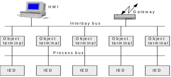
A typical system structure is shown in figure 1 below.
O b j e c t t e r m i n a l O b j e c t t e r m i n a l O b je c t t e r m in a l O b j e c t t e r m i n a l O b j e c t t e r m in a l I E D I E D I E D I E D I E D I n t e r b a y b u s P r o c e s s b u s G a t e w a y H M I
Figure 1. System structure for intelligent switchgear
4. MODERNIZATION OF A SWEDISH 220 kV SUBSTATION- Untra
The Untra substation is owned by Svenska Kraftnät (Swedish Transmission Grid). The existing Untra substation was mainly built 40 years ago close to a generator station in the Dalaälven, 200 km north of Stockholm. It gets infeed from a 40 MW generator station and interconnects 4 overhead lines on 230 kV. The existing busbar arrangement is main- and transfers bus for the feeders and with a 200 m extension of the main bus to a breaker in the generator station. This means that there were 5 breakers and 15 disconnectors in the existing station. The station had to be upgraded because disconnectors, instrument transformers and protection and control system had to be exchanged. The control equipment had to be placed in a new house inside the substation area instead of, as before, in the generator station.
4.1 Simplified busbar arrangement
The first approach was to keep the existing substation arrangement, keep the breakers and replace all other HV components one by one. But as one goal was to minimise future maintenance work, the transfer bus was found to be obsolete. The transfer bus was earlier chosen to allow breaker maintenance without interruption of the main busbar or any feeder. On the other hand, transfer bus requires a lot of disconnectors. During disconnector service, one feeder or the entire station has to be taken out of service. A study showed that the single bus arrangement was extremely favourable from availability point of view. The busbar arrangement is shown in figure 2 below.
Figure 2. Busbar arrangement in Untra 220 kV substation
I-AIS
Existing
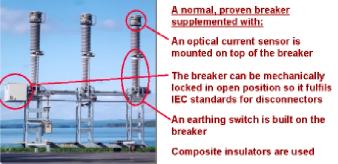
As a disconnector with contacts in open air has a relatively high demand for maintenance, in the same magnitude as modern SF6 breakers, it’s not quite advisable to install a disconnector to be opened only for breaker faults or maintenance. Therefore a disconnecting breaker has been introduced, which fulfils the IEC standard requirements both for breaker and disconnector. Choosing a normal breaker for the next voltage level, and to make it lockable in open position performs the disconnecting function. In addition there is an earthing switch outside the breaker. This new apparatus therefore has four positions:
- closed - open
- disconnected (locked in open position) - earthed on the feeder side
An example of a disconnecting breaker arrangement is shown in figure 4 below.
Figure 3 The disconnecting breaker
4.3 Sensors with optical communication
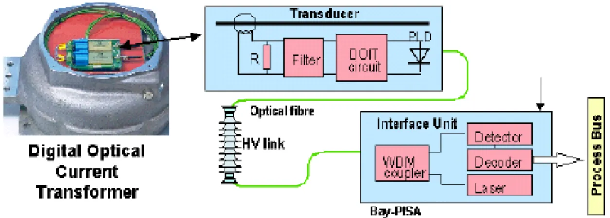
On top of the disconnecting breaker is installed a current sensor with optical communication. A small linear CT placed on high potential measures the current. The signal is converted to optical digital signal sampled by 4 kHz with 1 microsecond accuracy. It is suitable for both metering and protection requirements and has been used in thousands of installations for series compensators the last 10 years. An optical fibre inside the breaker takes the optical signal down to earth and to a so-called Bay-PISA (see below) where it is converted to the process bus.
The current measuring unit DOCT gives the following benefits: • digital output obtained already in the sensor
• small size, easy installation • no saturation
• no additional errors in the secondary circuits • reduced secondary cabling
Neptun, Romania
Fig. 4 Digital Optical Current Transformer, DOCT – photo and principle.
The voltage is measured by a Digital Optical Voltage Transformer, DOVT, which consists of a CVT but where the secondary signal is taken through a pure capacitive divider to a transducer of the same design as for the DOCT. The voltage signal is also available on the process bus.
The busbar DOVT has a DOCT mounted on the top, which measures the current to the generator station. This unit is together with its secondary equipment performing a complete metering module with a total system accuracy of class 0.5. Still the single current and voltage signals are available on the process bus.
4.4 Breaker monitoring
Each breaker is equipped with an On-Line Monitoring equipment, OLM. By this equipment the breaker condition is continuously monitored giving support for a reliability centred maintenance for optimisation of maintenance resources. Every operation in the breaker history is stored and may be analysed and treated with respect of prevailing environmental condition.
Various features are included like travel, damping, SF6-density,etc.
Fig. 5 On-Line Monitoring – OLM
4.5 PPH – the 100 Mbit Process bus
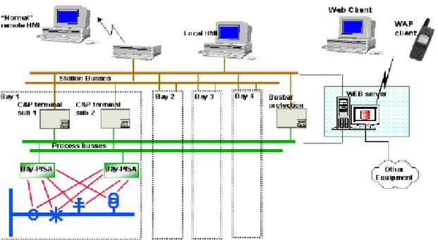
The Power Process Highway transmits all process information between the control room equipment and the switchyard with enough speed and accuracy. The design is based on a duplicated system for all buses and terminals. The local MMI is connected to one
Intranet) is connected to the PPH.
Fig 6. Schematic view of the control and protection system
4.6 Data Acquisition and Control Units (DACU) as concentrator
All signals in the switchyard are taken to or from a DACU (Bay-PISA), one for each redundant sub-system. Then the DACU is connected to the central control system via the process bus. Therefore the long distance cabling is reduced to two optical fibres and one power supply per DACU.
4.7 Integrated, redundant protection and control
Double sensors duplicate the optical current and voltage measurements. All process information is transmitted on two redundant process busses. The control and protection functions for each bay are combined in one physical unit. They are arranged in two redundant systems, one for local control and one for remote control, each with full protection functions.
The control and protection for each feeder consists of:
sub 1: Line terminal with distance protection, earth-fault protection, auto- reclosing, synchro check and remote control
sub 2: Line terminal with distance protection, earth-fault protection, auto-restoring and synchro check and local control.
for the busbar: Numerical differential protection
The entire C&P equipment consists of one DACU (REP 500) and one line terminal per subsystem. The space requirements are therefore very limited. The DACU is housed in a small marshalling kiosk close to the breaker, the line terminal is housed in a small wall mounted box in the control building. The control building also houses the busbar protection, a central cubicle for communication computers and the local screen and also the telecommunication equipment. The entire control house is factory assembled and transported as one unit to site where it is placed on top of a small cellar housing the
Neptun, Romania batteries. The control house is only 40 m2. The protection equipment is too small to be housed in cubicles. The equipment is placed in wall mounted boxes, 1 box per bay and subsystem. Cable channels below and above give physical sub distance.
Figure 7. Wall mounted protection and control equipment
5. WEB-SERVER FOR EFFICIENT ACCESS OF INFORMATION
The station is equipped with a web-server based on the iWabb concept. The main objective with iWabb is to have one application that gathers, processes and stores all relevant substation information and makes it legible through one interface. The iWabb can be used by operation, service and maintenance personnel in their office, in their homes or on any other place via WAP telephone. Via an easy Internet connection and self-instructing navigation, the user can easily navigate within the station from wherever situated. In addition to all the real-time data, the final documentation for the station is integrated in iWabb, in an object-oriented approach. This open access to all Substation Information, means lower life cycle costs and a safer method for maintenance decisions Wide Area Networks will connect the substation to the Office LAN with a high-speed TCP / IP communication link. iWabb uses thin clients (e.g. standard web browsers) and is not depending at all of client installations, licence costs etc. With certain levels of security anyone at the utility office will have authority to monitor the information previously locked up in old substations. With VPN (Virtual Private Network) suppliers and experts have a secure Internet connection to the same WAN and are able to discuss situations with the local engineers.
6.
SUMMARY
A general tendency for substations is to simplify the busbar arrangements and reduce the number of HV components in order to save investment and maintenance cost with maintained availability. With a Process bus (PPH) all information is available in the substation, and the system can be continuously supervised.
New HV modules, integrating several functions, have been introduced in order to reduce the over all Life Cycle Cost and to reduce the space for Air Insulated Substations. Normally these new integrated modules are equipped with some system for condition monitoring which further reduce the Life Cycle Cost.
E C Valbo 1 Valbo 1 Valbo 2 Valbo 21 Bredåker Bredåker Horndal Horndal Samlingsskena E C E C E C E C E C E C E C E C