for Automatic Parallel Generation
of Tetrahedral Grids
Form durch Fotokopie, Mikrofilm oder andere Verfahren zu reproduzieren
oder in eine für Maschinen, insbesondere Datenverarbeitungsanlagen,
ver-wendbare Sprache zu übertragen. Dasselbe gilt für das Recht der öffentlichen
Wiedergabe.
Warennamen werden ohne Gewährleistung der freien Verwendbarkeit benutzt.
Die Veröffentlichungen in der Berichtsreihe des Fraunhofer ITWM können
bezogen werden über:
Fraunhofer-Institut für Techno- und
Wirtschaftsmathematik ITWM
Fraunhofer-Platz 1
67663 Kaiserslautern
Germany
Telefon: +49 (0) 6 31/3 16 00-10 10
Telefax: +49 (0) 6 31/3 16 00-10 99
E-Mail: [email protected]
Internet: www.itwm.fraunhofer.de
Das Tätigkeitsfeld des Fraunhofer Instituts für Techno- und Wirtschaftsmathematik
ITWM umfasst anwendungsnahe Grundlagenforschung, angewandte Forschung
sowie Beratung und kundenspezifische Lösungen auf allen Gebieten, die für
Tech-no- und Wirtschaftsmathematik bedeutsam sind.
In der Reihe »Berichte des Fraunhofer ITWM« soll die Arbeit des Instituts
konti-nuierlich einer interessierten Öffentlichkeit in Industrie, Wirtschaft und
Wissen-schaft vorgestellt werden. Durch die enge Verzahnung mit dem Fachbereich
Ma-thematik der Universität Kaiserslautern sowie durch zahlreiche Kooperationen mit
internationalen Institutionen und Hochschulen in den Bereichen Ausbildung und
Forschung ist ein großes Potenzial für Forschungsberichte vorhanden. In die
Be-richtreihe sollen sowohl hervorragende Diplom- und Projektarbeiten und
Disser-tationen als auch Forschungsberichte der Institutsmitarbeiter und Institutsgäste zu
aktuellen Fragen der Techno- und Wirtschaftsmathematik aufgenommen werden.
Darüberhinaus bietet die Reihe ein Forum für die Berichterstattung über die
zahlreichen Kooperationsprojekte des Instituts mit Partnern aus Industrie und
Wirtschaft.
Berichterstattung heißt hier Dokumentation darüber, wie aktuelle Ergebnisse aus
mathematischer Forschungs- und Entwicklungsarbeit in industrielle Anwendungen
und Softwareprodukte transferiert werden, und wie umgekehrt Probleme der
Pra-xis neue interessante mathematische Fragestellungen generieren.
Prof. Dr. Dieter Prätzel-Wolters
Institutsleiter
DOMAIN DECOMPOSITION APPROACH FOR AUTOMATIC
PARALLEL GENERATION OF TETRAHEDRAL GRIDS
Evgeny G. Ivanov*, Heiko Andrä
†, Alexey N. Kudryavtsev
‡*Fraunhofer ITWM,
Fraunhofer-Platz 1, 67663 Kaiserslautern, Germany
e-mail: [email protected]
Web page: http://www.itwm.fhg.de/en/hpc__ansprechpartner__ivanov/ivanov/
†Fraunhofer ITWM,
Fraunhofer-Platz 1, 67663 Kaiserslautern, Germany
e-mail: [email protected]
Web page: http://www.itwm.fhg.de/en/sks__employees__andrae/andrae/
‡
Institute of Theoretical and Applied Mechanics, Siberian Division of RAS,
Institutskaya str. 4/1, 630090, Novosibirsk, Russia
e-mail: [email protected]
Web page:
http://www.itam.nsc.ru/users/alex/
Key words:
Grid Generation, Unstructured Grid, Delaunay Triangulation, Parallel
Programming, Domain Decomposition, Load Balancing
Abstract.
The desire to simulate more and more geometrical and physical features of
technical structures and the availability of parallel computers and parallel numerical solvers
which can exploit the power of these machines have lead to a steady increase in the number
of grid elements used. Memory requirements and computational time are too large for usual
serial PCs. An a priori partitioning algorithm for the parallel generation of 3D
nonoverlapping compatible unstructured meshes based on a CAD surface description is
presented in this paper. Emphasis is given to practical issues and implementation rather than
to theoretical complexity. To achieve robustness of the algorithm with respect to the
geometrical shape of the structure authors propose to have several or many but relatively
simple algorithmic steps. The geometrical domain decomposition approach has been applied.
It allows us to use classic 2D and 3D high-quality Delaunay mesh generators for independent
and simultaneous volume meshing. Different aspects of load balancing methods are also
explored in the paper. The MPI library and SPMD model are used for parallel grid generator
implementation. Several 3D examples are shown.
1 INTRODUCTION
Unstructured mesh techniques take an important place in grid generation. The main feature
of unstructured grids consists, in contrast to structured grids, in almost complete absence of
restrictions on grid cells, grid organization, or grid structure. It allows placing the grid nodes
locally irrespective of any coordinate direction, so that complex geometries with curved
boundaries can be meshed easily and local regions in which variations of the solution are
large or the accurate solution is of interest can be resolved with a selective insertion of new
points without unduly affecting the resolution in other parts of the physical domain. Local
adaptive mesh refinement can be easily done.
Unstructured grid methods
were originally developed in
solid mechanics. Nowadays
these methods influence many
other fields of applications
beyond solid modeling, in
particular computational fluid
dynamics where they are
becoming widely adopted.
At the present time the
methods of unstructured grid
generation have reached the stage where three-dimensional domains with complex geometry
can be automatically meshed. The most spectacular theoretical and practical achievements
with respect to automation have been connected with the techniques for generating tetrahedral
grids. There are at least two basic approaches that have been used to generate these
computational meshes: The Delaunay [1] and
advancing front [2]. In this paper we are dealing with
Delaunay approaches only. Delaunay property means
that the hypersphere of each n-dimensional simplex
defined by n+1 points is void of any other points of
the triangulation (Fig. 1). This empty circum-circle
property is the reason why the grid cells of a
Delaunay triangulation are without small or large
angles [3].
The most well-known or widely-used Delaunay
triangulation algorithms are the “Divide & Conquer”
algorithm [4] and the incremental insertion algorithm
[5].
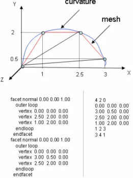
A CAD object description is a set of points, curves,
surfaces and solids that model the object. There are
many different standards. Two well-known ones are
IGES, which is popular in the US, and STEP, created
by the International Standard Organization. We use a
triangular surface mesh as an approximation. Standard
formats for surface triangulations are STL
(stereolithography format) and OFF (object file
format). In Fig. 2 two triangles approximating curved
surface are written in these formats. The STL format
Figure 1: left – triangles which satisfy Delaunay circum-circle
property; middle- triangles which do not satisfy Delaunay property;
right - Delaunay triangulation, all triangles are Delaunay
Figure 2: Two well-known surface
triangulation formats: STL
(stereolithography format) in the left
column and OFF (object file) in the right
is shown on the left side of Fig. 2. It specifies triangular surfaces with normals. The OFF
format is shown on the right side and specifies vertices coordinates and their incidents.
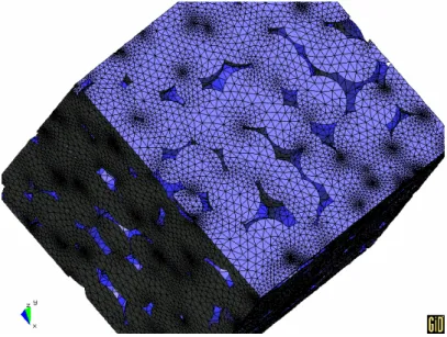
The introduction of scalable parallel computers is enabling ever-larger problems to be
solved in such areas as Computational Mechanics (CM), Computational Fluid Dynamics
(CFD) and Computational Electro Magnetics (CEM). Grids in excess of
10
7elements have
become common for production runs in CFD [6-10] and CEM [11,12]. The expectation is that
in the near future grids in excess of
10
8−
10
9elements will be required [13]. As mesh cell
numbers become as large as this (Fig. 3), the process of mesh generation on a serial computer
becomes problematic both in terms of time and memory requirements. For applications where
remeshing is an integral part of simulations, e.g. problems with moving bodies [14-20] or
changing topologies [21,22], the time required for mesh regeneration can easily consume
more than 50% of the total time required to solve the problem [13]. Faced with that problem,
a number of efforts have been reported on parallel grid generation [13,23-44].
Starting in two dimensions, Verhoeven et al. [44] demonstrated the ability to produce
parallel unstructured Delaunay meshes across a network of workstations. Topping et al. [45],
Laemer et al. [46], Loehner et al. [23], amongst others, have parallelized the advancing front
algorithm. Moving to three dimensions, the task becomes more complicated. Chew et al. [28],
Chrisochoides et al. [47], Okunsanya et al. [29] have parallelized the Delaunay algorithm.
Loehner [25] has demonstrated the extension of the advancing front algorithm to produce
tetrahedral elements on parallel platforms. Said et al. [30] have shown parallel mesh
generation using initial coarse meshing and decomposition.
There are two methods to parallelize a mesh generator; parallelize the algorithm directly
or decompose the problem. The latter is based on domain decomposition and can be classified
into a priori and a posteriori
partitioning algorithms [48].
Cignoni et al. [37,38], for
instance, investigated algorithms
for the parallelization of Delaunay
triangulation. Different solutions
were designed and evaluated. The
first one, which is a parallel
implementation of the “Divide &
Conquer” paradigm, was faster but
showed limited scalability. The
second one performs a regular
geometric partition of the dataset
and subdivides the load among
m
independent asynchronous
processors, using on each node an
incremental construction algorithm
(InCoDe); this solution is
algorithmically quite simple and
Figure 3: Computer generated stochastic representative volume
element (RVE) of sinter material for the computation of effective
allows sufficiently good scalability. It is used for computer graphics applications.
Chetverushkin et al. [39] suggested another algorithm based on initial a posteriori
partitioning, where the volumetric mesh generation procedure includes three main stages. The
first one consists of surface meshing using the initial geometric model. The constructed
surface mesh forms a base for the subsequent domain splitting into a set of large tetrahedrons.
This is a stage of primary volumetric triangulation and the number of these tetrahedrons
usually is moderate. At the third stage of the process the mesh of primary tetrahedrons is
refined to the necessary resolution and the resulting 3D mesh is smoothed and optimized if
necessary.
Recently, Ivanov [31,43] introduced and developed an a priori partitioning algorithm for
the parallel generation of three-dimensional unstructured grids using the domain
decomposition approach, i.e. decomposing the problem. This paper provides an extensive
description of the new algorithm stressing practical issues and implementation. To achieve
robustness of the algorithm the authors prefer to have several or many relatively simple
algorithmic steps rather than complex algorithms such as mentioned above.
The paper is organized as follows: Section 2 formulates the problem, gives an extensive
description of the algorithm and explores load balancing and partitioning methods.
In Section
3, the results are discussed and a complex geometry example is shown. Section 4 summarizes
and concludes the paper.
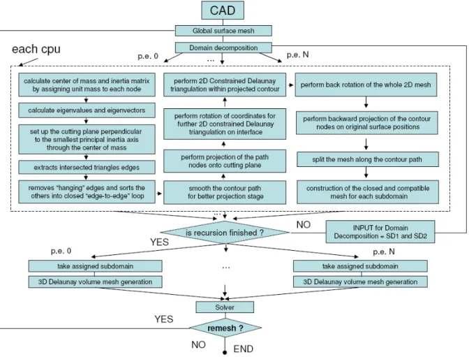
2 PARALLEL GENERATION ALGORITHM
The goal of the work is to create a parallel grid generator for high-quality unstructured
volume tetrahedral grids with good properties for solving PDEs (e.g. Delaunay property). It
should be fully automatic, adaptive (via coupling with the solver) and, of course, be able to
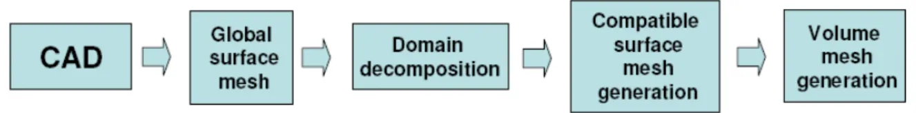
generate large meshes. The input data is a CAD surface description of an object. In fig. 4 the
main steps of implementation are shown.
The domain decomposition approach is used for a parallel grid generation. The algorithm
consists of several major steps:
1.
Load balanced recursive decomposition of an object into open subdomains.
a.
Center of mass and inertia matrix calculation for setting up the cutting plane.
b.
Smoothing of a cross-section contour for projection.
c.
Projection of the contour nodes to the plane for further interface triangulation.
2.
Construction of 2D constrained Delaunay triangulation on the projected interface.
3.
Mapping back the contour nodes of the triangulation to original surface positions.
4.
Construction of closed and compatible surface mesh for each subdomain.
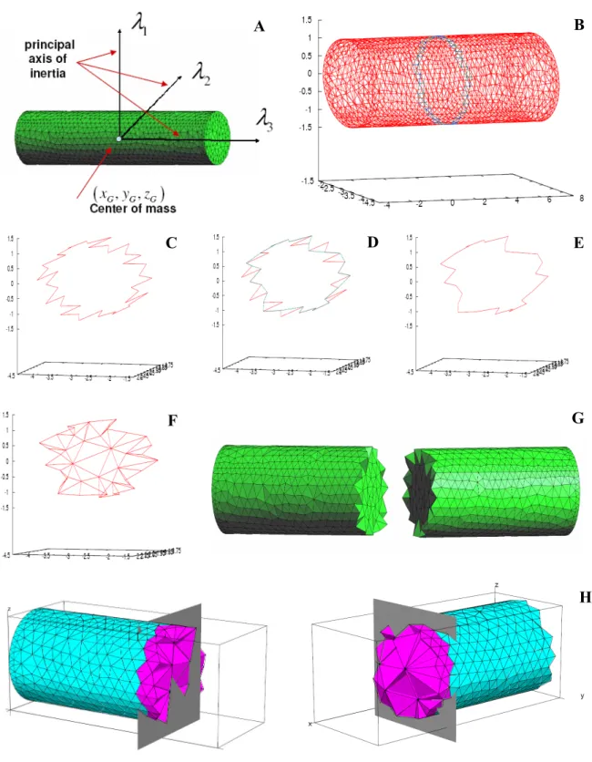
Figure 5: Major steps of the algorithm. A – center of mass and inertia matrix calculation. B – seting up the
cutting plane. C – closed loop of intersected edges. D – smothing the contour. E – smoothed contour of
edges. F – interface triangulation and mapping the contour nodes back. G – construction of closed and
compatible surface mesh. H – parallel independent construction of volume mesh inside (shown in pink).
C
A
B
D
E
F
G
5.
Independent parallel volume meshing (without communication) within each
subdomain based on its surface mesh description.
In Fig. 5 the major steps of the algorithm are shown. The smallest principal inertia axis is
chosen as splitting criterion in order to achieve good load-balancing and minimize
cross-section interface area. The goal of the parallel generation algorithm is to perform
simultaneous construction of three-dimensional grid in each subdomain. This is
computationally most expensive step of the algorithm.
The advantage of this algorithm is that it allows us to use sequential classic 2D and 3D
Delaunay triangulators, which are capable of producing high-quality Delaunay meshes with
different conditions and constraints. They are widely available [49]. The programs
Triangle
from Shewchuk [50] and
TetGen
from Hang Si [51] have been used for 2D and 3D
triangulation.
The disadvantage of this method is that domain decomposition is not always effective and
depends on the shape of an object. Therefore it needs to be continuously improved and
extended for different shapes (non-convex, long, and thin).
The detailed flow chart of the parallel grid generator is shown in Fig. 6.
Details of the algorithm are given in the following paragraphs.
2.1 Setting the cutting planes up and load balancing
Load balancing always has been a big issue for parallel applications. Several techniques
and criteria are considered in the paper.
Prepartition along the same direction.
The object is partitioned along several parallel
partitioning planes. A partitioning of an object into N subdomains would require N-1 parallel
tasks. The partitioning can be done in parallel.
Recursive prepartitioning.
An object is cut in two. Then for each part a new cutting plane
is determined and the parts are cut in two and so on. Note, that first task is sequential, second
task involves two parallel tasks, and the k th step involves
2
k−1tasks.
Overdecomposition.
An object is decomposed into many subdomains. The number of
subdomains is much larger than the number of processors. Then in the case of load imbalance
the master process gives the task (subdomain) to idle processor.
The partitioning criteria for the object decomposition could be volume, number of
boundary facets, number of nodes, moment of inertia.
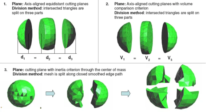
Going through developing stages the parallel grid generator had different partitioning
techniques and splitting criteria (see Fig. 7). Axis-aligned equidistant planes can result in
Figure 7: Evolution of the parallel grid generator. 1 – equidistant axis-aligned cutting. 2 – axis-aligned cutting
with volume comparison. 3 – recursive cutting with moment of inertia equality.
imbalanced partitioning depending on the shape of the object because the scheme it is not
sensitive to the object shape and can not be applied to arbitrary geometries. The axis-aligned
cutting with volume comparison criterion produces balanced partitioning, but it also can result
in a large interface area, which is not optimal for further interface triangulation and crucial for
a parallel solver, because of communication overhead between subdomains.
Here the center of gravity along with moment of inertia criterion is used. Each object is cut
perpendicular to its smallest principal inertia axis. It means that for each part with the set of
nodes V, the inertia matrix is computed by eq. (1), where ( ,
x y z
G G,
G)
is the coordinate of the
center of gravity which is calculated by assigning unit mass to each node of the mesh. Thus
grid resolution is also taken into account. Then (one of) the eigenvector(s) with the smallest
eigenvalue is selected.
This procedure defines planes perpendicular to the smallest principal inertia axis. The
actual cutting plane is chosen to go through the center of gravity. This partitioning technique
is sensitive to the object shape and grid resolution and can minimize the interface area.
Nevertheless it turns out to be hard to find a reasonable criterion for predicting a good load
balancing in advance. Even if the number of tetrahedra is approximately the same for each
subdomain, the CPU time spent for the volume meshing of each part can be quite different
[32].
2.2 Construction of the splitting contour
Once the cutting plane is defined, we can construct a cross-section contour where 2D
constrained Delaunay triangulation will be performed.
It is very important to partition a mesh in such a way that it does not deteriorate
significantly the grid quality. In [43] we employed the following division method: The
intersected triangle was divided into three other smaller triangles. Additional nodes were
inserted, so that the final contour consisted of the intersection lines of the plane with boundary
facets (Fig. 7). Obviously, this splitting can cause “bad triangles” – triangles with very acute
angle or small area. Proposed in [52] sophisticated mesh optimization technique was used in
order to overcome this problem and improve the quality of the mesh.
Here we present more advanced technique. The construction of the contour consists of the
following steps:
1. Extract all intersected edges of the surface triangulation.
2. Remove all edges with “hanging” node.
3. Sort the edges into a closed loop.
(
) (
)
(
)
(
)(
)
(
)(
)
(
)(
)
(
(
) (
)
)
(
)(
)
(
)(
)
(
)(
)
(
(
) (
)
)
2 2 2 2 2 2 G P G P G P G P G P G P P P P G P G P G P G P G P G P P P P G P G P G P G P G P G P P P Py
y
z
z
x
x
y
y
x
x
z
z
I
x
x
y
y
x
x
z
z
y
y
z
z
x
x
z
z
x
x
z
z
x
x
y
y
−
+
−
−
−
−
−
−
−
= −
−
−
−
+
−
−
−
−
−
−
−
−
−
−
−
+
−
∑
∑
∑
∑
∑
∑
∑
∑
∑
(1)
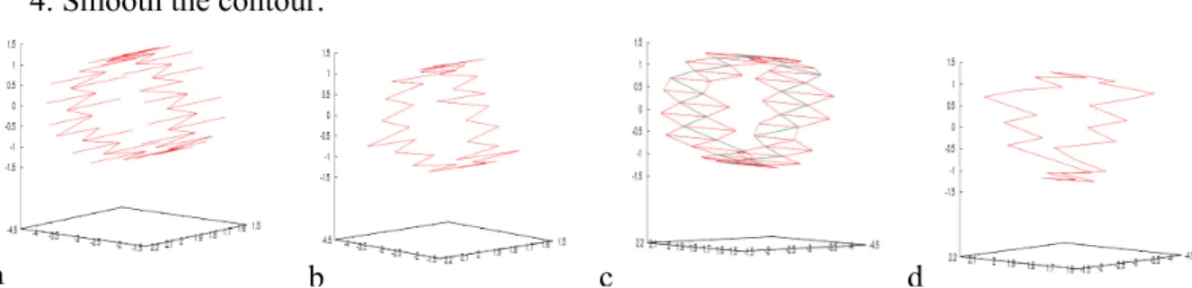
4. Smooth the contour.
Figure 8: Steps of the contour construction. a – extract all intersected edges. b – remove edges with “hanging”
nodes. c – replace two edges in the loop with third one for triangles which have three nodes in the path. d –
smoothed contour of edges.
The smoothing step requires more detailed explanation. We consider all triangles attached
to the path of edges and for those triangles, which have two edges in the path we replace them
with third edge. The smoothing phase is required for better further projection on the cutting
plane and construction of 2D triangulation of interface. Next section is devoted to that
problem.
2.3 Construction of interface and 2D
constrained Delaunay triangulation
Two steps are required before the 2D
triangulation of the interface can be done:
1.
Projection of the contour nodes on
the cutting plane.
2.
Rotation into X-Y plane of the
coordinates for 2D triangulation.
The program
Triangle
by Shewchuk [50]
is used for triangulation of the interface.
In three dimensions a coordinate
rotation can be described by a 3x3 matrix
M, which rotates a coordinate by an angle
θ
around a unit vector
v
,
After triangulation of the interface with certain constraints on minimal angle and maximum
triangle area, the coordinates are reversed back and the contour nodes are mapped back on
their original surface positions (fig. 9).
Figure 9: red – nodes projected on the cutting plane, green
– rotation of coordinates into X-Y plane, blue –
triangulation of interface and mapping the contour nodes
back on original positions
( )
(
(
)
(
)
)
(
(
)
(
)
) (
(
)
)
(
(
)
)
(
)
(
) (
)
(
)
(
)
2
2
2
cos
1 cos
1 cos
sin
1 cos
sin
,
1 cos
sin
cos
1 cos
1 cos
sin
1 cos
sin
1 cos
sin
cos
1 cos
x
yx
z
zx
y
M v
yx
z
y
zy
x
zx
y
zy
x
z
θ
θ
θ
θ
θ
θ
θ
θ
θ
θ
θ
θ
θ
θ
θ
θ
θ
θ
θ
⎡
+ −
−
+
−
+
⎤
⎢
⎥
=
⎢
−
+
+ −
−
−
⎥
⎢
−
+
−
+
+ −
⎥
⎣
⎦
. (2)
a
b
c
d
2.4 Splitting the mesh along the path of edges
It is not that obvious how to split the mesh
along the path of edges. For the triangles which
are not intersected it is clear. One just has to
check whether this triangle on the right or on
the left side of the cutting plane. Another
situation is with intersected triangles. Here we
should take into account the smoothness of the
contour.
Let us recall, that after smoothing phase,
there are no triangles which have two edges in
the path, since they were replaced with the
third edge. So the intersected triangles have
two vertices in the edge path and one free
vertex on a left or right side of the path. Hence,
triangle belongs to that part, where this free
vertex is located. Fig. 10 explains the
implemented technique.
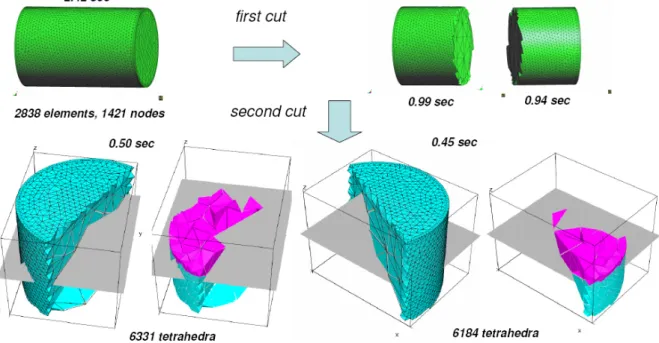
2.5 Parallel volume mesh construction
When balanced partitioning is done and a closed and compatible surface mesh is
constructed for each subdomain the volume meshes are constructed in parallel.
TetGen
- a
Figure 10: red – splitting path of edges, blue – the
mesh. (V
1,V
2,V
3) and (V’
1,V’
2,V’
3) vertices of two
triangles. V
2and V’
3are free vertices (not in the
path). Thus triangle (V
1,V
2,V
3) belongs to left
subdomain and triangle (V’
1,V’
2,V’
3) to right
subdomain
quality tetrahedral mesh generator and three-dimensional Delaunay triangulator from Hang Si
[51] has been used for volume Delaunay tetrahedralization with certain quality bound
(radius-edge ratio), a maximum volume bound, a maximum area bound on a facet, a maximum (radius-edge
length on a segment. Fig. 11 shows an example of partitioning and final tetrahedralization
inside of the subdomains on 4 CPUs.
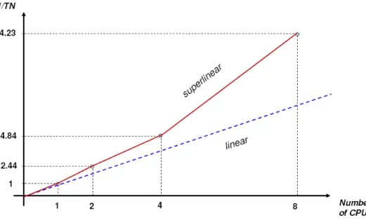
3 RESULTS AND DISCUSSION
The generation time of the volume mesh for the whole computational domain is that time,
which is spent on generation of a volume mesh in one subdomain with the highest
computational effort. The flip-based algorithm
TetGen
uses is from Edelsbrunner and Shah
[53]. The complexity of the algorithm is
O n
( )
2in worst case. In practice this algorithm has a
nearly linear complexity
O n
(
log
n
)
. In Fig. 12 a speed-up graph is shown for the mesh of
Fig. 11. The speed-up here is better than linear. It is “super-linear” due to the fact that
complexity of the algorithm is higher than
O n
( )
. When we divide our problem into
sub-problems and solve them in parallel we get, of course, a super-linear scaling. Note, that there
is no any communication overhead, since construction of the volume mesh is performed
absolutely independent and does not require any data exchange.
Figure 12: Speed-up of volume mesh generation time (shown in red) without
prepartitioning time
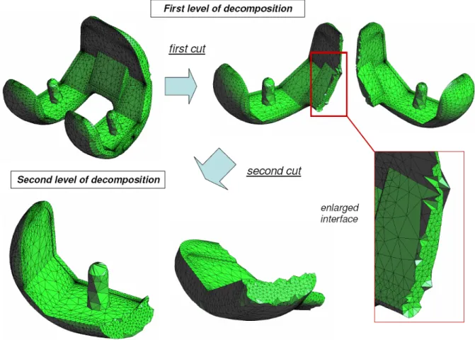
3.1 Numerical test example
In Fig. 13 numerical example of knee prosthesis component is shown [55]. It was
partitioned by using developed partitioning algorithm for 4 CPUs (see Fig. 14).
3.2 Surface and volume mesh quality
It was already mentioned that the mesh
quality is an important property to pay
attention to. The partitioning algorithm
should not adversely affect the quality of
the surface mesh. The most undesirable
triangles for FEM calculations are those
with very acute angles. Figure 15 shows
how our partitioning algorithm affects
mesh quality. “Bad triangles” (shown in
red) with angle less than 30° are shown
before and after partitioning.
For the volume tetrahedral mesh there
are several measures available in the
literature. Here the quality measure used
in
TetGen
will be described [54]. For high
Figure 13: Total knee prosthesis component.
accuracy in the FEM, it is generally necessary that the shapes of tetrahedra have bounded
aspect ratio. The aspect ratio of a tetrahedron is the ratio of the maximum side length to the
minimum height. For a quality mesh, this value should be as small as possible. For example
“thin and flat” tetrahedra tend to have a large aspect ratio.
A similar but weaker quality measure is radius-edge ratio. The radius-edge ratio
Q
is the
ratio of the circumsphere radius
R
to the length of the shortest edge
L,
defined by
R
Q
L
=
(3)
For all well-shaped tetrahedra, this value is small, while for most of badly-shaped
tetrahedra, this value is large [56] (see Fig. 16).
A special type of badly-shaped tetrahedron is called “sliver”, which is very flat and nearly
degenerate. Slivers can have radius-edge ratio as small as 2 / 2 0.707
≈
. The radius-edge
ratio is not a proper measure for slivers.
TetGen
does a simplified sliver removal step. Slivers
are removed by local flip operations and peeling off from the boundary.
After tetrahedralization automatic mesh quality evaluation is performed and a mesh quality
report on the smallest and largest volume, the shortest and longest edge, the smallest and
largest dihedral angle, radius-edge ratio histogram, aspect ratio histogram, dihedral angle
histogram is printed.
Figure 16: The radius-edge ratio for some well-shaped and badly-shaped tetrahedra. a – the radius-edge ratio
for some well-shaped tetrahedra. b – the radius-edge ratios for some badly-shaped tetrahedra. c – sliver
(special type of badly-shaped tetrahedron)
4 SUMMARY AND CONCLUSIONS
A method to generate 3D unstructured nonoverlapping meshes in parallel has been
demonstrated. An a priori algorithm based on domain decomposition has been used. This
problem allows us to use standard sequential 2D and 3D triangulators in parallel. The
programs
Triangle
[50] and
TetGen
[51] were employed for construction of 2D and 3D
high-quality Delaunay meshes. Different aspects of load balancing methods and criteria such as
prepartitioning along the same direction and recursive partitioning based on moment of inertia
splitting criterion are also explored in the paper. The partitioning algorithm is demonstrated
for a knee prosthesis component with emphasis on mesh quality. The parallelization strategy
is based on SPMD computational model and employs the MPI library for the implementation
of the parallel grid generator. Hence, the most expensive computations, the generation of the
volume mesh inside each subdomain is completely independent and performed in parallel. A
superlinear speed-up of volume mesh construction time has been observed. This fact is due to
complexity of Delaunay mesh construction which is higher than
O n
( )
.
The parallel grid generator has two important benefits over traditional Delaunay
generators, the time required to generate a mesh is shorter than that from a sequential
generator, and the memory required for each CPU to generate a mesh is lower in comparison
to that of a sequential mesh generator. This enables us to work with larger meshes than it
would be possible with sequential generators.
An a priori partitioning algorithm is clearly advantageous in terms of computational time
and memory usage compare to an a posteriori method used by mesh partitioning libraries such
as METIS [57], since we perform first partitioning and then volume meshing, while an a
posteriori method partition already constructed volume mesh.
a
Further work on testing, creating of programming interface with CAD, handling of
examples with more complex geometries and larger meshes and performing local adaptive
mesh refinement is in progress.
5 AKNOWLEDGEMENTS
This work is supported by the DAAD, TU Kaiserslautern, Fraunhofer Institute for
Industrial Mathematics and Institute of Theoretical and Applied Mechanics SD RAS. The
authors are grateful to Dimitar Stoyanov and Robert Zillich for their contribution to that work
and corrections of the paper. The authors wish to thank Academician S.K. Godunov for his
interest to this work and many comments on subject.
REFERENCES
[1] B. Delaunay, “Sur la sphère vide”
, Izvestia Akademii Nauk SSSR, Otdelenie
Matematicheskikh i Estestvennykh Nauk,
7
, 793-800 (1934)
[2] H Jin, R. I. Tanner, ”Generation of Unstructured Tetrahedral Meshes by the Advancing
Front Technique”,
Int. J. Num. Meth. Engng
.,
36
, 1805-1823 (1993)
[3] V. D. Liseikin,
Grid Generation Methods
, Springer-Verlag Berlin Heidelberg, 1999
[4] P.Cignoni, C. Montani, R. Scopigno, “DeWall: A Fast Divide & Conquer Delaunay
Triangulation Algorithm in Ed”,
Computer-Aided Design., Elsevier Science
,
30(5)
, 333-
341 (1998)
[5] L.J. Guibas, D.E. Knuth and M.Sharir, ”Randomized incremental construction of
Delaunay and Voronoy diagrams”,
Springer-Verlag, Lect. Note Comp. Science
,
443
,
414-431 (1990)
[6] J.D. Baum, H. Luo and R. Löhner, “Numerical Simulation of a Blast Inside a Boeing
747”,
AIAA-93-3091
(1993)
[7] J.D. Baum, H. Luo and R. Löhner, “Numerical Simulation of a Blast in the World Trade
Center”,
AIAA-95-0085
(1995)
[8] W. Jou, “Comments on the Feasibility of LES for Commercial Airplane Wings,
AIAA-98-2801
(1998)
[9] S. Yoshimura, H. Nitta, G. Yagawa and H. Akiba, "Parallel Automatic Mesh Generation
Method of Ten-million Nodes Problem Using Fuzzy Knowledge Processing and
Computational Geometry",
Proc. 4th World Congress on Computational Mechanics
(WCCM-IV) (CD-ROM)
(1998)
[10] D.J. Mavriplis and S. Pirzadeh, “Large-Scale Parallel Unstructured Mesh Computations
for 3-D High Lift Analysis”,
ICASE Rep
.
99-9
(1999)
[11] E. Darve and R. Löhner, “Advanced Structured-Unstructured Solver for Electromagnetic
Scattering from Multimaterial Objects”,
AIAA-97-0863
(1997)
[12] K. Morgan, P.J. Brooks, O. Hassan and N.P. Weatherill, ”Parallel Processing for the
Simulations of Problems Involving Scattering of Electromagnetic Waves”,
in Proc. Symp.
Advances in Computational Mechanics (L. Demkowicz and J.N. Reddy eds)
(1997)
[13] R. Löhner and J.R. Cebral, “Parallel Advancing Front Grid Generation”,
Proceedings, 8th
International Meshing Roundtable,
67-74 (1999)
[14] R. Löhner, “Three-Dimensional Fluid-Structure Interaction Using a Finite Element
Solver and Adaptive Remeshing”,
Comp. Sys. In Eng.
1
, 2-4, 257-272 (1990)
[15] E. Mestreau, R. Löhner and S. Aita, “TGV Tunnel-Entry Simulations Using a Finite
Element Code with Automatic Remeshing”,
AIAA-96-0798
(1996)
[16] E. Mestreau and R. Löhner, “Airbag Simulations Using Fluid/Structure Coupling”,
AIAA-96-0798
(1996)
[17] J.D. Baum, H. Luo and R. Löhner, C. Yang, D. Pelessone and C. Charman, “A Coupled
Fluid/Structure Modeling of Shock Interaction with a Truck”,
AIAA-96-0795
(1996)
[18] A. Kamoulakos, V. Chen, E. Mestreau and R. Löhner, “Finite Element Modeling of
Fluid/Structure Interaction in Explosively Loaded Aircraft Fuselage Panels Using
PAMSHOCK/PAMFLOW Coupling”,
Conf. on Spacecraft Structures, Materials and
Mechanical Testing
, (1996)
[19] R. Löhner, C. Yang, J. Cebral, J.D. Baum, H. Luo, D. Pelessone, and C. Charman,
“Fluid-Structure-Thermal Interaction Using a Loose Coupling Algorithm and Adaptive
Unstructured Grids”,
AIAA-98-2419
(1998)
[20] O. Hassan, L.B. Bayne, K. Morgan and N.P. Weatherill, “An Adaptive Unstructured
Mesh Method for Transient Flows Involving Moving Boundaries”,
5th US Congress on
Computational Mechanics,
662-674 (1999)
[21] J.D. Baum, H. Luo and R. Löhner, “The Numerical Simulation of Strongly Unsteady
Flows With Hundreds of Moving Bodies”,
AIAA-98-0788
(1998)
[22] J.D. Baum, H. Luo, E. Mestreau, R. Löhner, D. Pelessone and C. Charman, “A coupled
CFD/CSD Methodology for Modeling Weapon Detonation and Fragmentation”,
AIAA-99-0794
(1999)
[23] R. Löhner, J. Camberos and M. Merriam, “Parallel Unstructured Grid Generation”,
Comp. Meth. Appl. Mech. Eng. 95
, 343-357 (1992)
[24] H.L. de Cougny. M.S. Shephard and C. Ozturan, “Parallel Three-Dimensional Mesh
Generation”,
Computing Systems in Engineering
5
, 311-323 (1994)
[25] A. Shostko and R. Löhner, “Three-Dimensional Parallel Unstructured Grid Generation”,
Int. J. Num. Meth. Eng.
38
, 905-925 (1995)
[26] H.L. de Cougny. M.S. Shephard and C. Ozturan, “Parallel Three-Dimensional Mesh
Generation on Distributed Memory MIMD Computers”,
Tech. Rep. #7, Rensselaer
Polytechnic Institute
(1995)
[27] T. Okunsanya and J. Peraire, “Parallel Unstructured Mesh Generation”,
Proc. 5th Int.
Conf. Num. Grid Generation in CFD and Related Fields
(1996)
[28] L.P. Chew, N. Chrisochoides and F. Sukup, “Parallel Constrained Delaunay Meshing”,
Proc. Workshop on Trends in Unstructured Mesh Generation,
(1997)
[29] T. Okunsanya and P. Peraire, “3-D Parallel Unstructured Mesh Generation”,
Proc. Joint
ASME/ASCE/SES Summer Meeting
(1997)
[30] R. Said, N.P. Weatherill, K. Morgan and N.A.Verhoeven, “Distributed Parallel Delaunay
Mesh Generation”,
Comp. Meth. Appl. Mech. Eng
.
177
, 109-125 (1999)
Proceedings of Conference on Stability and Turbulence of Homogeneous and
Heterogeneous Fluids Flows
, 79-82 (2005)
[32] J. Galtier, P.L. George, “Prepartitioning as a Way to Mesh Subdomains in Parallel”,
5th
International Meshing Roundtable, Sandia National Laboratories
, 107-122 (1996)
[33] B.G. Larwood, N.P. Weatherill, O. Hassan and K. Morgan, “Domain Decomposition
Approach for Parallel Unstructured Mesh Generation”,
Int. J. Num. Meth. Eng.
58
,
177-188 (2003)
[34] N. Chrisochoides and Demian Nave, “Parallel Delaunay Mesh Generation Kernel”,
Int. J.
Num. Meth. Eng.
58
, 161-176 (2003)
[35] P. Wu and E. N. Houstis, “Parallel Adaptive Mesh Generation and Decomposition“,
Engineering with Computers
12
, 155-167 (1996)
[36] N. Chrisochoides and Demian Nave, “Simultaneous Mesh Generation and Partitioning
for Delaunay Meshes”,
Proceedings, 8th International Meshing Roundtable,
55-66
(1999)
[37] P. Cignoni, C. Montani, R. Perego, R. Scopigno, “Parallel 3D Delaunay Triangulation”,
Computer Graphics Forum
12(3),
129-142 (1993)
[38] P. Cignoni, D. Laforenza, C. Montani, R. Perego, and R. Scopigno, “Evaluation of
parallelization strategies for an incremental Delaunay triangulator in E3”,
Practice and
Experience
7(1),
61-80 (1995)
[39] B.N. Chetverushkin, V.A. Gasilov, S.V. Polyakov, M.V. Iakobovski, E.L. Kartasheva,
A.S. Boldarev, A.S. Minkin, “Data Structures and Mesh Processing in Parallel CFD
Project GIMM”,
Proc. ParCo2005
(2005)
[40] A.J. Barragan, J.S. Reeve, “Parallel, Three-Dimensional Finite Element Mesh Generation
Based on Octree Data Structures”,
European Congress on Computational Methods in
Applied Sciences and Engineering,
(2000)
[41] N. Chrisochoides, A. Chernikov and K. Barker, “Parallel Programming Environment for
Mesh Generation”,
Proceedings of ICNGG
(2002)
[42] C.Walshaw, M.Cross, and M.G. Everett. Parallel Unstructured Mesh Partitioning.
Domain Decomposition Methods in Sciences and Engineering
, 647-654 (1998)
[43] E.G. Ivanov, “Automatic Parallel Generation of Three-Dimensional Unstructured Grids
for Computational Mechanics”,
Journal of Computational Technologies
.
11(1)
, 3-17
(2006)
[44] N. A. Verhoeven, N. P. Weatherill, K. Morgan “Dynamic load balancing in a 2D parallel
Delaunay mesh generator”,
Proceedings of the Parallel CFD Conference
(1995)
[45] B.H.V. Topping, B. Cheng Parallel and distributed adaptive quadrilateral mesh
generation,
Computers and Structures
73
, 519-536 (1999)
[46] L. Laemer, M. Burghardt, “Parallel generation of triangular and quadrilateral meshes”,
Advances in Engineering Software
31,
929-936 (2000)
[47] N. Chrisochoides, D. Nave, “Simultaneous mesh generation and partitioning for
Delaunay meshes”,
Mathematics and Computers in Simulation
54,
321-339 (2000)
[48] P.L. George, H. Borochaki, “
Delaunay Triangulation and Meshing: Application to Finite
Elements
”, Editions HERMES, 1998
[50] J. R. Shewchuk, "Triangle: Engineering a 2d quality mesh generator and delaunay
triangulator,"
Proceedings first workshop on Applied Computational Geometry
, 124-133
(1996)
[51] H. Si, K. Gaertner, “Meshing Piecewise Linear Complexes by Constrained Delaunay
Tetrahedralizations”,
Proceeding of the 14th International Meshing Roundtable
, (2005)
[52] H. Hoppe, T. DeRose, T. Duchamp, J. McDonald, W. Stuetzle, „Mesh optimization”,
ACM SIGGRAPH,
19-26 (1993)
[53] H. Edelsbrunner and N. R. Shah, “Incremental Topological Flipping Works for Regular
Triangulations”,
Algorithmica
15
, 223-241 (1996)
[54] J. R. Shewchuk, Tetrahedral Mesh Generation by Delaunay Refinement.
Proceedings of
the Fourteenth Annual Symposium on Computational Geometry
, 86-95 (1998)
[55]
http://www.lima.it/english/prostheses/products/multigen.html
[56] Hang Si, “TetGen. A Quality Tetrahedral Mesh Generator and Three-Dimensional
Delaunay Triangulator. Version 1.4. User’s Manual”, (2006)
[57] METIS: Multilevel Partitioning Algorithms, available at
http://www-users.cs.umn.edu/~karypis/metis/
The PDF-files of the following reports
are available under:
www.itwm.fraunhofer.
de/de/zentral__berichte/berichte
1. D. Hietel, K. Steiner, J. Struckmeier
A Finite - Volume Particle Method for
Compressible Flows
We derive a new class of particle methods for conser-vation laws, which are based on numerical flux func-tions to model the interacfunc-tions between moving par-ticles. The derivation is similar to that of classical Finite-Volume methods; except that the fixed grid structure in the Finite-Volume method is substituted by so-called mass packets of particles. We give some numerical re-sults on a shock wave solution for Burgers equation as well as the well-known one-dimensional shock tube problem.
(19 pages, 1998)
2. M. Feldmann, S. Seibold
Damage Diagnosis of Rotors: Application
of Hilbert Transform and
Multi-Hypothe-sis Testing
In this paper, a combined approach to damage diag-nosis of rotors is proposed. The intention is to employ signal-based as well as model-based procedures for an improved detection of size and location of the damage. In a first step, Hilbert transform signal processing tech-niques allow for a computation of the signal envelope and the instantaneous frequency, so that various types of non-linearities due to a damage may be identified and classified based on measured response data. In a second step, a multi-hypothesis bank of Kalman Filters is employed for the detection of the size and location of the damage based on the information of the type of damage provided by the results of the Hilbert trans-form.
Keywords: Hilbert transform, damage diagnosis, Kal-man filtering, non-linear dynamics
(23 pages, 1998)
3. Y. Ben-Haim, S. Seibold
Robust Reliability of Diagnostic Multi-
Hypothesis Algorithms: Application to
Rotating Machinery
Damage diagnosis based on a bank of Kalman filters, each one conditioned on a specific hypothesized sys-tem condition, is a well recognized and powerful diag-nostic tool. This multi-hypothesis approach can be ap-plied to a wide range of damage conditions. In this pa-per, we will focus on the diagnosis of cracks in rotating machinery. The question we address is: how to opti-mize the multi-hypothesis algorithm with respect to the uncertainty of the spatial form and location of cracks and their resulting dynamic effects. First, we formulate a measure of the reliability of the diagnostic algorithm, and then we discuss modifications of the diagnostic algorithm for the maximization of the reliability. The reliability of a diagnostic algorithm is measured by the amount of uncertainty consistent with no-failure of the diagnosis. Uncertainty is quantitatively represented with convex models.
Keywords: Robust reliability, convex models, Kalman filtering, multi-hypothesis diagnosis, rotating machinery, crack diagnosis
(24 pages, 1998)
4. F.-Th. Lentes, N. Siedow
Three-dimensional Radiative Heat Transfer
in Glass Cooling Processes
For the numerical simulation of 3D radiative heat trans-fer in glasses and glass melts, practically applicable mathematical methods are needed to handle such problems optimal using workstation class computers.
5. A. Klar, R. Wegener
A hierarchy of models for multilane
vehicular traffic
Part I: Modeling
In the present paper multilane models for vehicular traffic are considered. A microscopic multilane model based on reaction thresholds is developed. Based on this model an Enskog like kinetic model is developed. In particular, care is taken to incorporate the correla-tions between the vehicles. From the kinetic model a fluid dynamic model is derived. The macroscopic coef-ficients are deduced from the underlying kinetic model. Numerical simulations are presented for all three levels of description in [10]. Moreover, a comparison of the results is given there.
(23 pages, 1998)
Part II: Numerical and stochastic
investigations
In this paper the work presented in [6] is continued. The present paper contains detailed numerical inves-tigations of the models developed there. A numerical method to treat the kinetic equations obtained in [6] are presented and results of the simulations are shown. Moreover, the stochastic correlation model used in [6] is described and investigated in more detail. (17 pages, 1998)
6. A. Klar, N. Siedow
Boundary Layers and Domain
Decompos-ition for Radiative Heat Transfer and
Diffu-sion Equations: Applications to Glass
Manu-facturing Processes
In this paper domain decomposition methods for radia-tive transfer problems including conducradia-tive heat trans-fer are treated. The paper focuses on semi-transparent materials, like glass, and the associated conditions at the interface between the materials. Using asymptotic analysis we derive conditions for the coupling of the radiative transfer equations and a diffusion approxi-mation. Several test cases are treated and a problem appearing in glass manufacturing processes is com-puted. The results clearly show the advantages of a domain decomposition approach. Accuracy equivalent to the solution of the global radiative transfer solution is achieved, whereas computation time is strongly re-duced.
(24 pages, 1998)
7. I. Choquet
Heterogeneous catalysis modelling and
numerical simulation in rarified gas flows
Part I: Coverage locally at equilibrium
A new approach is proposed to model and simulate numerically heterogeneous catalysis in rarefied gas flows. It is developed to satisfy all together the follow-ing points:
1) describe the gas phase at the microscopic scale, as required in rarefied flows,
2) describe the wall at the macroscopic scale, to avoid prohibitive computational costs and consider not only crystalline but also amorphous surfaces,
3) reproduce on average macroscopic laws correlated with experimental results and
4) derive analytic models in a systematic and exact way. The problem is stated in the general framework of a non static flow in the vicinity of a catalytic and non po-rous surface (without aging). It is shown that the exact and systematic resolution method based on the La-place transform, introduced previously by the author to model collisions in the gas phase, can be extended to the present problem. The proposed approach is applied to the modelling of the EleyRideal and LangmuirHinshel-wood recombinations, assuming that the coverage is locally at equilibrium. The models are developed con-sidering one atomic species and extended to the
gener-Efficient Texture Analysis of Binary Images
A new method of determining some characteristics of binary images is proposed based on a special linear fil-tering. This technique enables the estimation of the area fraction, the specific line length, and the specific integral of curvature. Furthermore, the specific length of the total projection is obtained, which gives detailed information about the texture of the image. The influ-ence of lateral and directional resolution depending on the size of the applied filter mask is discussed in detail. The technique includes a method of increasing direc-tional resolution for texture analysis while keeping lat-eral resolution as high as possible.
(17 pages, 1998)
9. J. Orlik
Homogenization for viscoelasticity of the
integral type with aging and shrinkage
A multiphase composite with periodic distributed in-clusions with a smooth boundary is considered in this contribution. The composite component materials are supposed to be linear viscoelastic and aging (of the nonconvolution integral type, for which the Laplace transform with respect to time is not effectively ap-plicable) and are subjected to isotropic shrinkage. The free shrinkage deformation can be considered as a ficti-tious temperature deformation in the behavior law. The procedure presented in this paper proposes a way to determine average (effective homogenized) viscoelastic and shrinkage (temperature) composite properties and the homogenized stressfield from known properties of the components. This is done by the extension of the asymptotic homogenization technique known for pure elastic nonhomogeneous bodies to the nonhomo-geneous thermoviscoelasticity of the integral noncon-volution type. Up to now, the homogenization theory has not covered viscoelasticity of the integral type. SanchezPalencia (1980), Francfort & Suquet (1987) (see [2], [9]) have considered homogenization for viscoelas-ticity of the differential form and only up to the first derivative order. The integralmodeled viscoelasticity is more general then the differential one and includes almost all known differential models. The homogeni-zation procedure is based on the construction of an asymptotic solution with respect to a period of the composite structure. This reduces the original problem to some auxiliary boundary value problems of elastic-ity and viscoelasticelastic-ity on the unit periodic cell, of the same type as the original non-homogeneous problem. The existence and uniqueness results for such problems were obtained for kernels satisfying some constrain conditions. This is done by the extension of the Volterra integral operator theory to the Volterra operators with respect to the time, whose 1 kernels are space linear operators for any fixed time variables. Some ideas of such approach were proposed in [11] and [12], where the Volterra operators with kernels depending addi-tionally on parameter were considered. This manuscript delivers results of the same nature for the case of the spaceoperator kernels.
(20 pages, 1998)
10. J. Mohring
Helmholtz Resonators with Large Aperture
The lowest resonant frequency of a cavity resonator is usually approximated by the classical Helmholtz formu-la. However, if the opening is rather large and the front wall is narrow this formula is no longer valid. Here we present a correction which is of third order in the ratio of the diameters of aperture and cavity. In addition to the high accuracy it allows to estimate the damping due to radiation. The result is found by applying the method of matched asymptotic expansions. The cor-rection contains form factors describing the shapes of opening and cavity. They are computed for a number of standard geometries. Results are compared with nu-merical computations.
are considered) and the fixed cardinality case (i.e. only cycles with a given cardinality p are feasible). Hence it is of interest to investigate special cases where the prob-lem is solvable in polynomial time. In grid graphs, the variable cardinality case is, for instance, trivially solvable if the shape of the cycle can be chosen freely. If the shape is fixed to be a rectangle one can analyze rectangles in grid graphs with, in sequence, fixed di-mension, fixed cardinality, and variable cardinality. In all cases a complete characterization of the optimal cycles and closed form expressions of the optimal objective values are given, yielding polynomial time algorithms for all cases of center rectangle problems.
Finally, it is shown that center cycles can be chosen as rectangles for small cardinalities such that the center cycle problem in grid graphs is in these cases com-pletely solved.
(15 pages, 1998)
12. H. W. Hamacher, K.-H. Küfer
Inverse radiation therapy planning -
a multiple objective optimisation approach
For some decades radiation therapy has been proved successful in cancer treatment. It is the major task of clinical radiation treatment planning to realize on the one hand a high level dose of radiation in the cancer tissue in order to obtain maximum tumor control. On the other hand it is obvious that it is absolutely neces-sary to keep in the tissue outside the tumor, particularly in organs at risk, the unavoidable radiation as low as possible.
No doubt, these two objectives of treatment planning - high level dose in the tumor, low radiation outside the
tumor - have a basically contradictory nature. Therefore, it is no surprise that inverse mathematical models with dose distribution bounds tend to be infeasible in most cases. Thus, there is need for approximations compro-mising between overdosing the organs at risk and un-derdosing the target volume.
Differing from the currently used time consuming it-erative approach, which measures deviation from an ideal (non-achievable) treatment plan using recursively trial-and-error weights for the organs of interest, we go a new way trying to avoid a priori weight choices and consider the treatment planning problem as a mul-tiple objective linear programming problem: with each organ of interest, target tissue as well as organs at risk, we associate an objective function measuring the maxi-mal deviation from the prescribed doses.
We build up a data base of relatively few efficient solu-tions representing and approximating the variety of Pa-reto solutions of the multiple objective linear program-ming problem. This data base can be easily scanned by physicians looking for an adequate treatment plan with the aid of an appropriate online tool.
(14 pages, 1999)
13. C. Lang, J. Ohser, R. Hilfer
On the Analysis of Spatial Binary Images
This paper deals with the characterization of micro-scopically heterogeneous, but macromicro-scopically homo-geneous spatial structures. A new method is presented which is strictly based on integral-geometric formulae such as Crofton’s intersection formulae and Hadwiger’s recursive definition of the Euler number. The corre-sponding algorithms have clear advantages over other techniques. As an example of application we con-sider the analysis of spatial digital images produced by means of Computer Assisted Tomography.
(20 pages, 1999)
14. M. Junk
On the Construction of Discrete Equilibrium
Distributions for Kinetic Schemes
A general approach to the construction of discrete equilibrium distributions is presented. Such distribution functions can be used to set up Kinetic Schemes as well as Lattice Boltzmann methods. The general principles
A new discrete velocity method for
Navier-Stokes equations
The relation between the Lattice Boltzmann Method, which has recently become popular, and the Kinetic Schemes, which are routinely used in Computational Fluid Dynamics, is explored. A new discrete veloc-ity model for the numerical solution of Navier-Stokes equations for incompressible fluid flow is presented by combining both the approaches. The new scheme can be interpreted as a pseudo-compressibility method and, for a particular choice of parameters, this interpretation carries over to the Lattice Boltzmann Method. (20 pages, 1999)
16. H. Neunzert
Mathematics as a Key to Key Technologies
The main part of this paper will consist of examples, how mathematics really helps to solve industrial prob-lems; these examples are taken from our Institute for Industrial Mathematics, from research in the Techno-mathematics group at my university, but also from ECMI groups and a company called TecMath, which originated 10 years ago from my university group and has already a very successful history.
(39 pages (4 PDF-Files), 1999)
17. J. Ohser, K. Sandau
Considerations about the Estimation of the
Size Distribution in Wicksell’s Corpuscle
Problem
Wicksell’s corpuscle problem deals with the estima-tion of the size distribuestima-tion of a populaestima-tion of particles, all having the same shape, using a lower dimensional sampling probe. This problem was originary formulated for particle systems occurring in life sciences but its so-lution is of actual and increasing interest in materials science. From a mathematical point of view, Wicksell’s problem is an inverse problem where the interest-ing size distribution is the unknown part of a Volterra equation. The problem is often regarded ill-posed, be-cause the structure of the integrand implies unstable numerical solutions. The accuracy of the numerical so-lutions is considered here using the condition number, which allows to compare different numerical methods with different (equidistant) class sizes and which in-dicates, as one result, that a finite section thickness of the probe reduces the numerical problems. Fur-thermore, the relative error of estimation is computed which can be split into two parts. One part consists of the relative discretization error that increases for in-creasing class size, and the second part is related to the relative statistical error which increases with decreasing class size. For both parts, upper bounds can be given and the sum of them indicates an optimal class width depending on some specific constants.
(18 pages, 1999)
18. E. Carrizosa, H. W. Hamacher, R. Klein,
S. Nickel
Solving nonconvex planar location
prob-lems by finite dominating sets
It is well-known that some of the classical location problems with polyhedral gauges can be solved in poly-nomial time by finding a finite dominating set, i. e. a finite set of candidates guaranteed to contain at least one optimal location.
In this paper it is first established that this result holds for a much larger class of problems than currently con-sidered in the literature. The model for which this result can be proven includes, for instance, location problems with attraction and repulsion, and location-allocation problems.
Next, it is shown that the approximation of general gauges by polyhedral ones in the objective function of our general model can be analyzed with regard to the subsequent error in the optimal objective value. For the approximation problem two different approaches are described, the sandwich procedure and the greedy
al-(19 pages, 2000)
19. A. Becker
A Review on Image Distortion Measures
Within this paper we review image distortion mea-sures. A distortion measure is a criterion that assigns a “quality number” to an image. We distinguish between mathematical distortion measures and those distortion measures in-cooperating a priori knowledge about the imaging devices ( e. g. satellite images), image process-ing algorithms or the human physiology. We will con-sider representative examples of different kinds of dis-tortion measures and are going to discuss them.
Keywords: Distortion measure, human visual system
(26 pages, 2000)
20. H. W. Hamacher, M. Labbé, S. Nickel,
T. Sonneborn
Polyhedral Properties of the Uncapacitated
Multiple Allocation Hub Location Problem
We examine the feasibility polyhedron of the unca-pacitated hub location problem (UHL) with multiple al-location, which has applications in the fields of air pas-senger and cargo transportation, telecommunication and postal delivery services. In particular we determine the dimension and derive some classes of facets of this polyhedron. We develop some general rules about lift-ing facets from the uncapacitated facility location (UFL) for UHL and projecting facets from UHL to UFL. By ap-plying these rules we get a new class of facets for UHL which dominates the inequalities in the original formu-lation. Thus we get a new formulation of UHL whose constraints are all facet–defining. We show its superior computational performance by benchmarking it on a well known data set.
Keywords: integer programming, hub location, facility location, valid inequalities, facets, branch and cut
(21 pages, 2000)
21. H. W. Hamacher, A. Schöbel
Design of Zone Tariff Systems in Public
Transportation
Given a public transportation system represented by its stops and direct connections between stops, we con-sider two problems dealing with the prices for the cus-tomers: The fare problem in which subsets of stops are already aggregated to zones and “good” tariffs have to be found in the existing zone system. Closed form solu-tions for the fare problem are presented for three ob-jective functions. In the zone problem the design of the zones is part of the problem. This problem is NP hard and we therefore propose three heuristics which prove to be very successful in the redesign of one of Germa-ny’s transportation systems.
(30 pages, 2001)
22. D. Hietel, M. Junk, R. Keck, D. Teleaga
The Finite-Volume-Particle Method for
Conservation Laws
In the Finite-Volume-Particle Method (FVPM), the weak formulation of a hyperbolic conservation law is dis-cretized by restricting it to a discrete set of test func-tions. In contrast to the usual Finite-Volume approach, the test functions are not taken as characteristic func-tions of the control volumes in a spatial grid, but are chosen from a partition of unity with smooth and over-lapping partition functions (the particles), which can even move along pre- scribed velocity fields. The infor-mation exchange between particles is based on stan-dard numerical flux functions. Geometrical information, similar to the surface area of the cell faces in the Finite-Volume Method and the corresponding normal direc-tions are given as integral quantities of the partition functions. After a brief derivation of the Finite-Volume-Particle Method, this work focuses on the role of the geometric coefficients in the scheme.