AS/400e series
X.25 Network Support
Version 4
AS/400e series
X.25 Network Support
Version 4
Note
Before using this information and the product it supports, be sure to read the general information in “Notices” on page 113.
Second Edition (September 1998)
Contents
About X.25 Network Support (SC41-5405). . . . vii
Who should read this book . . . vii
Conventions and terminology used in this book . . . vii
AS/400 Operations Navigator . . . viii
Installing Operations Navigator subcomponents . . . ix
Accessing AS/400 Operations Navigator . . . ix
Prerequisite and related information . . . x
How to send your comments . . . x
Chapter 1. Introducing X.25 . . . . 1
DTE-to-DCE Interface . . . 2
Physical Layer. . . 3
Data Link Control Layer . . . 4
Packet Layer . . . 4
Network Support of Non-X.25 DTEs . . . 6
Advantages of Using X.25 for Communications. . . 6
X.25 Service Charges . . . 7
X.25 Transmission on an Integrated Services Digital Network (X.31) . . . 8
Circuit Mode (X.31 Case A) . . . 8
Packet Mode (X.31 Case B). . . 9
Chapter 2. AS/400 Support of X.25 . . . 13
X.25 Virtual Circuit Support . . . 13
AS/400 X.25 Capabilities . . . 14
X.25 Line Description Configuration Considerations . . . 16
Network Subscription Considerations (DTE-to-DCE) . . . 16
X.25 Switched Line Considerations . . . 19
Connecting Systems without an X.25 Network (DTE-to-DTE) . . . 20
Chapter 3. End-to-End Connectivity Considerations. . . . 23
X.25-Specific Values . . . 23
PVC Functions . . . 24
SVC Functions . . . 24
SVC Incoming Call Function . . . 27
SVC Outgoing Call Function . . . 31
Calling DTE Information . . . 32
Status Information . . . 32
AS/400-Supported Protocols on an X.25 Virtual Circuit . . . 33
SNA Considerations. . . 33
SNA over X.25 . . . 34
Asynchronous Communications Considerations . . . 40
TCP/IP . . . 41
OSI . . . 41
IPX . . . 41
User-Defined Communications . . . 42
Chapter 4. Performance Considerations . . . . 43
Line Speed . . . 43
Protocol Efficiency . . . 43
Packet Processing Capacity. . . 43
Physical Layer Errors . . . 45
Data Link Control Errors . . . 45
X.25 Packet Layer Errors. . . 45
Finding Cause and Diagnostic Codes . . . 46
Determining the Meaning of Cause and Diagnostic Codes . . . 46
Chapter 6. X.25 Cause Codes . . . 49
X.25 Cause Codes Generated by the AS/400 System . . . 49
ITU-T X.25 and ISO-8208 Cause Codes . . . 50
Chapter 7. X.25 Diagnostic Codes . . . . 53
X.25 Diagnostic Codes Generated by the AS/400 System . . . 53
Diagnostic Codes Generated by the X.25 Network . . . 57
SNA Diagnostic Codes Generated by the DTE . . . 60
ITU-T X.25 and ISO-8208 Diagnostic Codes. . . 63
Chapter 8. X.25 Configuration Examples . . . . 67
Example 1: AS/400 System-to-X.25 PSDN Configuration . . . 67
Configurations on Local AS/400 System 499 . . . 69
Configurations on Remote AS/400 System 603. . . 77
Configurations on Host System . . . 78
Configurations on System/36 024. . . 80
System/36 X.25 Configuration . . . 83
Configurations on System/38 258. . . 86
Configurations for 5394 Controller and 5251 Display Station . . . 87
Configurations for 3274 Controller and 3279 Display Station . . . 89
Example 2: AS/400 System-to-AS/400 System X.25 Non-PSDN Configuration . 91 Configurations on AS/400 System 499 . . . 92
Configurations on AS/400 System 386 . . . 93
Example 3: AS/400 System-to-System/38 X.25 Non-PSDN Configuration . . . 94
Configurations on the AS/400 System 320 . . . 94
Configurations on System/38 262. . . 95
Example 4: AS/400 System-to-AS/400 System X.25 PSDN Switched Line Configuration . . . 96
Configuring System 340 . . . 97
Configuring System 324 . . . 98
Configuring System 015 . . . 98
Chapter 9. Connecting Personal Computers with X.3 Network PAD and Client Access . . . 101
System Requirements . . . 101
Topology . . . 102
Asynchronous and X.25 Considerations . . . 103
Fundamentals of SNA and Asynchronous Connections . . . 103
Logical Link Control Protocol . . . 103
Call User Data Format . . . 103
Initializing a Session . . . 105 Call Processing . . . 105 Performance Considerations . . . 106 AS/400 Configuration . . . 107 PC Configuration . . . 110 Network Configuration . . . 110 Example Configuration. . . 111 AS/400 Configuration . . . 111
Programming Interface Information . . . 115 Trademarks . . . 115 Bibliography . . . 117 AS/400 Publications. . . 117 Non-AS/400 Publications . . . 117 Index . . . 119
About X.25 Network Support (SC41-5405)
This book contains information about the X.25 network interface and how to use it on the AS/400 system. This information includes X.25 network concepts, examples, and information on preparation and configuration. Information for communications functions supported on the AS/400 system, such as ISDN, TCP/IP, OSI, IPX, and user-defined communications are described in the related publications referred to in the “Bibliography” on page 117.
Who should read this book
This publication is intended for programmers and support personnel responsible for configuring and maintaining AS/400 connections X.25 networks.
Before using this book, you must be familiar with the use of the AS/400 system. A knowledge of configuration concepts and X.25 networking will be helpful when using this book. Additionally, ISDN users should have some knowledge of X.25
networking on an ISDN.
This book should be used in conjunction with theCommunications Configuration, SC41-5401 book, to configure your X.25 network. After configuration is completed, this book can be used to improve network performance.
Conventions and terminology used in this book
The AS/400 displays in this book could be shown as they are presented through Graphical Access for AS/400, which is part of Client Access on the personal
computer. The example displays in this book could also be shown without Graphical Access for AS/400 available. Figure 1 on page viii shows both types of displays.
| | | | | | | | | | | | | |
AS/400 Operations Navigator
AS/400 Operations Navigator is a powerful graphical interface for Windows 95/NT clients. With AS/400 Operations Navigator, you can use your Windows 95/NT skills to manage and administer your AS/400 systems.
v You can work with basic operations (messages, printer output, and printers), job management, system configuration, network administration, security, users and groups, database administration, file systems, and multimedia.
v You can schedule regular system backups, work with Interprocess
Communication through application development, and manage multiple AS/400 systems through a central system by using Management Central. You can also customize the amount of Operations Navigator function that a user or user group can use through application administration.
v You can create a shortcut to any item in the explorer view of Operations
Navigator. For example, you can create a shortcut either to Basic Operations or to the items that are listed under Basic Operations (Messages, Printer Output, and Printers). You can even create a shortcut to an individual printer or use a shortcut as a fast way to open the item.
Figure 2 on page ix shows an example of the Operations Navigator display:
Figure 1. Types of AS/400 Displays | | | | | | | | | | | | | | | | | | | |
IBM recommends that you use this new interface. It has online help to guide you. While we develop this interface, you will still need to use either of the following to do some of your tasks:
v Graphical Access (which provides a graphical interface to AS/400 screens). Graphical Access is part of the base Client Access.
v A traditional emulator such as PC5250.
Installing Operations Navigator subcomponents
AS/400 Operations Navigator is packaged as separately installable subcomponents. If you are upgrading from a previous release of AS/400 Operations Navigator, only those subcomponents that correspond to the function that is contained in the previous release will be installed. If you are installing for the first time and you use the Typical or Minimum installation options, the following options are installed by default:
v Operations Navigator base support
v Basic operations (messages, printer output, and printers)
To install additional AS/400 Operations Navigator subcomponents, either use the
Custom installation option or use selective setup to add subcomponents after
Operations Navigator has been installed:
1. Display the list of currently installed subcomponents in the Component
Selection window of Custom installation or selective setup.
2. Select AS/400 Operations Navigator and click Details.
3. Select any additional subcomponents that you want to install and continue with
Custom installation or selective setup.
Note: To use AS/400 Operations Navigator, you must have Client Access installed
on your Windows 95/NT PC and have an AS/400 connection from that PC. For help in connecting your Windows 95/NT PC to your AS/400 system, consultClient Access for Windows 95/NT - Setup, SC41-3512.
Accessing AS/400 Operations Navigator
To access Operations Navigator after you install Client Access and create an AS/400 connection, do the following:
Figure 2. AS/400 Operations Navigator Display | | | | | | | | | | | | | | | | | | | | | | | | | | | | | |
2. Double-click the Operations Navigator icon to open Operations Navigator. You can also drag the icon to your desktop for even quicker access.
Prerequisite and related information
Use the AS/400 Information Center as a starting point for your AS/400 information needs. It is available in either of the following ways:
v The Internet at this uniform resource locator (URL) address: http://publib.boulder.ibm.com/html/as400/infocenter.html v On CD-ROM:AS/400e series Information Center, SK3T-2027.
The AS/400 Information Center contains browsable information on important topics such as Java, program temporary fixes (PTFs), and Internet security. It also contains hypertext links to related topics, including Internet links to Web sites such as the AS/400 Technical Studio, the AS/400 softcopy library, and the AS/400 home page.
For a list of related publications, see the “Bibliography” on page 117.
How to send your comments
Your feedback is important in helping to provide the most accurate and high-quality information. If you have any comments about this book or any other AS/400 documentation, fill out the readers’ comment form at the back of this book.
v If you prefer to send comments by mail, use the readers’ comment form with the address that is printed on the back. If you are mailing a readers’ comment form from a country other than the United States, you can give the form to the local IBM branch office or IBM representative for postage-paid mailing.
v If you prefer to send comments by FAX, use either of the following numbers: – United States and Canada: 1-800-937-3430
– Other countries: 1-507-253-5192
v If you prefer to send comments electronically, use this network ID: – IBMMAIL, to IBMMAIL(USIB56RZ)
– [email protected] Be sure to include the following: v The name of the book.
v The publication number of the book.
v The page number or topic to which your comment applies.
| | | | | | | | | | | | | | | || | | | | | | | | | | | | | | | | | | |
Chapter 1. Introducing X.25
The X.25 network interface is the three-layer interface between packet-mode data
terminal equipment (DTE)1and data circuit-terminating equipment (DCE)2that
exists in a packet-switching data network (PSDN) 3as defined by the
International Telecommunications Union - Telecommunications Standardization Sector (ITU-T) 4and the International Standards Organization (ISO).
The layers that comprise the X.25 network are:
Physical
Defines how a DTE is physically connected to its corresponding network DCE.
Data link control
Defines the procedures for the connection, error-free transfer of information, and disconnection between the DTE and the network DCE.
Packet
Defines the procedures necessary for establishing connections (virtual circuits) between DTEs, transferring information (in packets), and clearing connections.
This three-layer interface is referred to as the X.25 network. ITU-T publicizes this interface in a document called Recommendation X.25 that outlines standards for the connection of processing equipment to a packet-switching data network. ISO defines the data link control layer in Standard 7776 and the packet layer in Standard 8208.
This guide provides an overview of X.25, a discussion of AS/400 system support of X.25, and information on end-to-end connectivity using X.25. Some general
information about Recommendation X.25 is provided, but a knowledge of X.25 networks would be helpful when configuring your system.
The following sections provide a general discussion of an X.25 network, information on the parts that comprise the network, and how to use an integrated services digital network (ISDN) for X.25 transmissions.
Note: Throughout this publication, the termDTErefers to a system (for example,
an AS/400 system) or other remote facilities (for example, controllers) that want to communicate through an X.25 network. The termDCErefers to the interface of the systems to the X.25 network.
1. Data terminal equipment is the part of a data link that sends data, receives data, and provides the data communications control function according to protocols.
2. Data circuit-terminating equipment is equipment installed at the user’s premises that provides all the functions required to establish, maintain, and end a connection, and the signal conversion and coding between the data terminal equipment and the network. 3. Packet-switching data network is a communications network that uses packets to send data.
| | | | |
DTE-to-DCE Interface
Even though this DTE-to-DCE interface is standardized, the architecture allows it to be tailored to the specific needs of the DTE and the network. For an interface to work properly, both the DTE owner and the network administrator must configure their equipment according to a previously negotiated network subscription. The network subscription details the specific X.25 options to be used on the DTE-to-DCE interface.
All types of packet-mode DTEs may connect to an X.25 network; therefore, each DTE-to-DCE interface supported by the network may have a unique subscription. Because the ultimate goal of a DTE using X.25 is to communicate with a remote DTE, the network must be able to bridge any possible differences between the separate subscriptions of two communicating DTEs.
The X.25 standards define procedures for the connection of one packet-mode DTE directly to another without an intervening network. This connectivity, referred to by ISO as DTE-to-DTE, requires that one of the DTEs provide a subset of DCE functions. In the remainder of this section, whenever DTE-to-network connectivity is discussed, the information is also applicable to DTE-to-DTE connectivity, unless specified otherwise.
The DTE-to-DCE interface, illustrated in Figure 3 on page 3, supports the exchange of information among the individual X.25 network subscribers (DTEs).
The following sections discuss the X.25 network layers and connectivity illustrated in Figure 3.
Physical Layer
The physical layer defines how a DTE is physically connected to its corresponding network DCE. The medium between the DTE and the network DCE must be capable of duplex transmission.
CCITT Recommendation X.32 defines procedures for using physically-switched mediums for network connectivity. Due to the transient nature of switched mediums, Recommendation X.32 also includes ways to identify the calling DTE or DCE for billing or security reasons. The physical interface protocols supported by X.25 are defined in other ITU-T standards. Some of these standards include:
Recommendation X.21
Defines the physical characteristics and call control procedures for the DTE-to-DCE interface on a public data network.
Recommendation X.21 bis
Provides an interim definition for the interface between a DTE and a V-Series-type DCE for synchronous operation on public data networks.
D T E D T E PAD Recommendation X.25 Recommendation X.28 and X.29 Start-Stop DTE Leased Leased X.25 Network DTE Switched D C E Recommendation X.25 and X.32 D C E DCE Public-Switched Network RV2P126-5 Switched Physical Connection
Leased Physical Connection PVC
SVC
Start-Stop Connection Figure 3. DTE-to-DCE Interface
V-series recommendations
Define the physical layer for analog data communications. This includes the interface between a DTE and a synchronous modem (DCE).
Recommendation X.31
Defines the support of the X.25 protocol over integrated services digital networks (ISDNs).
See “AS/400 X.25 Capabilities” on page 14 for information on all of the physical interfaces supported by the AS/400 system for X.25.
Data Link Control Layer
The data link control layer defines the procedures for the connection, error-free transfer of information, and disconnection between the DTE and the network DCE. At the data link control layer, the information is transmitted between the two stations in data units called high-level data link control (HDLC) frames. Both the DTE and the network DCE are considered peer stations.
The link access protocol-balanced (LAPB) (a data link level protocol for using an X.25 network) subset of HDLC is used. Because of this peer relationship, constant polling is not required when the HDLC connection is established. Polling involves contacting the attached devices to avoid contention, to determine operational status, or to determine readiness to send or receive data. Either station can transmit frames as necessary to carry higher layer information. Depending on the network subscription, either the DTE or network DCE can begin the HDLC connection. However, the DTE normally disconnects the link when network connectivity is no longer required.
The link access procedure-D-channel (LAPD), recommended by the ITU-T, defines the data link control protocol used on an ISDN D-channel. LAPD may be used to carry both ISDN signalling data and X.25 packet data on the D-channel. The AS/400 system does not support LAPD.
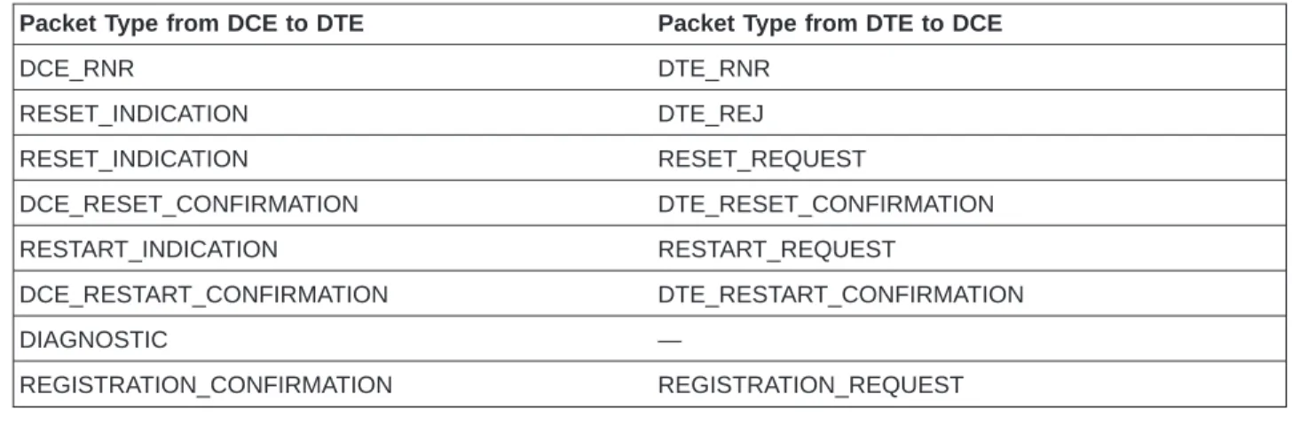
Packet Layer
The packet layer defines the procedures necessary for establishing connections (virtual circuits) between DTEs, transferring information (in packets), and clearing connections.
Table 1 illustrates the types of packets used in the X.25 network.
Table 1. Packet Types
Packet Type from DCE to DTE Packet Type from DTE to DCE
INCOMING_CALL CALL_REQUEST CALL_CONNECTED CALL_ACCEPTED CLEAR_INDICATION CLEAR_REQUEST DCE_CLEAR_CONFIRMATION DTE_CLEAR_CONFIRMATION DCE_DATA DTE_DATA DCE_INTERRUPT DTE_INTERRUPT DCE_INTERRUPT_CONFIRMATION DTE_INTERRUPT_CONFIRMATION
Table 1. Packet Types (continued)
Packet Type from DCE to DTE Packet Type from DTE to DCE
DCE_RNR DTE_RNR RESET_INDICATION DTE_REJ RESET_INDICATION RESET_REQUEST DCE_RESET_CONFIRMATION DTE_RESET_CONFIRMATION RESTART_INDICATION RESTART_REQUEST DCE_RESTART_CONFIRMATION DTE_RESTART_CONFIRMATION DIAGNOSTIC — REGISTRATION_CONFIRMATION REGISTRATION_REQUEST
Notice that even though a virtual circuit logically connects two DTEs, the packet layer in each DTE is actually a peer with the packet layer in its corresponding network DCE. This peer relationship between the packet layer in the DTE and the packet layer in the corresponding network DCE enables the network to translate any differences that may exist between the two DTE network subscriptions. Typically, an effect of this relationship is that X.25 provides no DTE-to-DTE acknowledgment of received data. ITU-T has defined a means for DTE-to-DTE packet acknowledgment called the delivery-bit (D-bit). However, not all DTEs or networks support this function. Depending on the quality of network service, some higher layer protocols using X.25 may incorporate their own end-to-end
acknowledgment scheme.
A DTE can simultaneously have multiple virtual circuits active to multiple DTEs. Each virtual circuit active on a network interface can have different characteristics. For example, maximum packet size or maximum number of outstanding
unacknowledged packets can vary among virtual circuits. To enable this
multiplexing, each DTE-to-DCE interface identifies individual virtual circuits using a uniquely assigned 12-bit identifier, called a logical channel. The assignment of a virtual circuit to a logical channel can be either on demand (switched) or static (permanent), depending on the network subscription.
To enable switched virtual circuit connectivity to a remote DTE, each DTE is assigned a unique network address as part of its network subscription. When switched connectivity is desired, the calling DTE initiates a call setup procedure with the network. As part of this procedure, the calling DTE supplies the network with the network address of the remote DTE. The calling DTE assigns logical channels on the calling interface. The DCE assigns logical channels on the called interface. Because logical channels are unique on each network interface, it is possible that the actual values used on each end of the switched virtual circuit (SVC) are different.
At call setup time, SVC characteristics are established. These characteristics are determined by the network subscription and the presence or absence of special fields in the call setup packets called facilities. These facility fields allow the DTE and DCE to negotiate SVC characteristics by determining which optional user facilities will be in effect. Certain user facilities allow transmission of call user data between DTEs on call setup packets. Several higher layer protocols, those layers not defined by X.25, reserve the first byte of this call user data as a protocol
identifier. The protocol identifier allows the called DTE to determine the exact higher layer protocol needed by the calling DTE.
Permanent virtual circuits (PVCs) are used to establish nonswitched connectivity to a remote DTE. PVC characteristics and their logical channels are statically defined in the network subscription. Provided the DTE-to-DCE interface on each end of a PVC is active at the packet layer, the virtual circuit is considered ready for information transfer.
One major network management function of the packet layer is the ability to send and receive status information on either a specific virtual circuit or all SVCs. This status information is carried in the cause and diagnostic code fields of certain packet types.
Network Support of Non-X.25 DTEs
ITU-T standardized an interface and procedures for the attachment of start-stop mode (asynchronous) DTEs to an X.25 network in Recommendation X.28. The DTE communicates with the X.25 network through a packet assembler/disassembler (PAD) facility. The PAD maps the X.28 protocol from the DTE to X.25 in the network direction, and from X.25 to X.28 in the DTE direction. Recommendation X.29 defines how a packet-mode DTE on the network can remotely tailor the
configuration of the PAD facility to meet the specific needs of the asynchronous DTE (for example, how and when data from the DTE should be forwarded to the network).
Other nonstandard equipment exists that performs PAD-like functions for DTEs supporting non-X.25 protocols other than asynchronous communications.
Advantages of Using X.25 for Communications
The layers of X.25 together provide many advantages including networking, standardization, multiplexing, information integrity, and dynamic negotiation of connection. The following sections describe some of these advantages.
Networking
X.25 allows DTE-to-DTE connectivity. The individual network subscribers are only responsible for the configuration, and perhaps attachment to the network
(depending on the network subscription), of their DTEs. The network administration is responsible for maintaining the equipment and transmission mediums inside the network to ensure connectivity.
Standardization
Unlike a proprietary protocol, X.25 is a standard defined by the ITU-T. Therefore, any DTE that conforms to Recommendation X.25 is able to perform packet communications with all other DTEs conforming to Recommendation X.25 without modification to the protocol. The network accommodates subscription differences so that DTEs with different subscriptions may communicate.
Multiplexing
X.25 has no requirement on what higher layer protocol uses the virtual circuits provided by the packet layer. Multiplexing means that of the several virtual circuits potentially active over a given interface at a particular time, each could be
Because the X.25 packet layer supports many virtual circuits on a single network interface, equipment cost is reduced.
Information Integrity
The X.25 data link control layer ensures the integrity of all information passed to the packet layer and to all higher layers.
Dynamic Negotiation of Connection Characteristics
If negotiation is allowed by the network subscription, different SVC characteristics can be established from call to call. This function allows the DTE to tailor its resources to the demand. For example, during periods when large numbers of SVCs are active, the packet sizes can be decreased to reduce DTE storage demands.
Some communications applications have additional requirements not addressed by X.25. These requirements include:
v End-to-end acknowledgment of received data v Transaction-based processing
v Data translation
v Multiplexing within a virtual circuit
Many communication applications do not interface directly to X.25. Instead, a higher layer protocol is used in a virtual circuit provided by X.25. Many higher layer
protocols are designed to operate in X.25 virtual circuits. These protocols include: v Asynchronous
v Open systems interconnection (OSI) v Systems Network Architecture (SNA)
v Transmission Control Protocol/Internet Protocol (TCP/IP) v Internetwork Packet Exchange (IPX)
v User-defined communications
The choice of which higher layer protocol, if any, to use on a given X.25 virtual circuit depends on the protocols supported by each of the communicating DTEs and the particular requirements of the application program.
See “AS/400-Supported Protocols on an X.25 Virtual Circuit” on page 33 for more information on the higher layer protocols supported by the AS/400 system that can make use of the connectivity provided by X.25.
X.25 Service Charges
Specific X.25 charging information (tariffs) is network-dependent. However, the most common method is a periodic subscription fee that covers network access and any subscribed PVCs. For SVCs, charging is similar to the access charges of a public-switched telephone network. If allowed by the subscription, the calling DTE can request, through a special facility code, that the SVC charges be reversed to the called DTE. The called DTE is informed that the calling DTE is requesting reverse charging and can choose to accept or clear the call.
The subscription fee may not cover the physical medium or communications equipment (the modem) used to access the network interface by a DTE. For
example, if a switched voice-grade line is used for X.25 network access, the customer can be billed separately by the public-switched telephone network. The choice between using an SVC or a PVC for connectivity to a particular DTE is made by estimating cost and use. According to Recommendation X.32, if any PVCs are to be requested in the network subscription, the physical medium to the network interface must be nonswitched. If only SVCs are required, then another estimation of cost and use can help determine whether the medium to the network should be physically switched.
X.25 Transmission on an Integrated Services Digital Network (X.31)
Recommendation X.31 provides a versatile network interface for X.25. The integrated services digital network (ISDN) physical layer is described by ITU-T Recommendations I.430 (basic rate interface) and I.431 (primary rate interface). These interfaces consist of a single D-channel and two or more B-channels. The
B-channels (bearer channels) transmit digital data between end users at a rate of
64 000 bits per second (bps). A B-channel may be switched, which means that it is established on demand, or it may be permanent, which means that it always exists and is available for use. The D-channel communicates the necessary information for call setup, call ending, and other call control between a system and the ISDN. With ISDN, several time-multiplexed channels are available on one network interface. Additional channels allow X.25 connections to exist with other types of connections, and each channel can offer a different service. Thus, an ISDN physical interface can have capabilities for fax, image, packet-switched data transmission, circuit switching, and voice transmission. The ISDN potentially provides all these services. When the X.25 protocol is used with an ISDN, the digital end-to-end connectivity eliminates the need for modems. This leads to faster communication speed with fewer errors.
Because ISDN provides the D-channel for signalling, the system can selectively accept calls based on the information received on the signalling channel. This leaves B-channels free for other purposes or for continuing the current activity without interruption.
CCITT Recommendation X.31 defines two modes of accessing an X.25 network through an ISDN. One mode, known as circuit mode, uses the ISDN B-channel as a high-speed transmission medium to access a packet-switching data network (PSDN). The other mode, known as packet mode, uses an ISDN B-channel or D-channel to use the packet services integrated in the ISDN. Both modes use the D-channel to establish a switched B-channel connection to the X.25 DCE. The two modes are described in “Circuit Mode (X.31 Case A)” and “Packet Mode (X.31 Case B)” on page 9. Some network providers may not support the services defined by X.31.
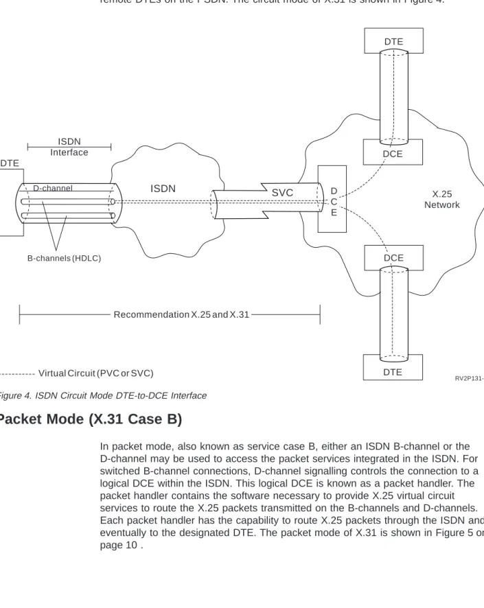
Circuit Mode (X.31 Case A)
In circuit mode, also known as service case A, a DTE uses an ISDN B-channel as a high-speed transportation medium to a DCE in the PSDN. This B-channel may be either permanent or switched. If the B-channel is switched, D-channel call control sets up the B-channel connection. Once this connection is established, X.25 packet communications is transparent to the ISDN. The DTE uses the B-channel for its HDLC connection to the DCE. Then it can establish virtual circuit connections to
remote DTEs on the PSDN. The circuit mode of X.31 is shown in Figure 4.
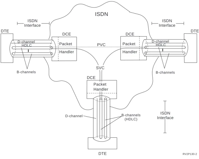
Packet Mode (X.31 Case B)
In packet mode, also known as service case B, either an ISDN B-channel or the D-channel may be used to access the packet services integrated in the ISDN. For switched B-channel connections, D-channel signalling controls the connection to a logical DCE within the ISDN. This logical DCE is known as a packet handler. The packet handler contains the software necessary to provide X.25 virtual circuit services to route the X.25 packets transmitted on the B-channels and D-channels. Each packet handler has the capability to route X.25 packets through the ISDN and eventually to the designated DTE. The packet mode of X.31 is shown in Figure 5 on page 10 . X.25 Network D-channel B-channels (HDLC) DTE DTE DTE D C E DCE DCE ISDN SVC ISDN Interface Recommendation X.25 and X.31 Virtual Circuit (PVC or SVC) RV2P131-2
Certain information regarding an X.25 call is encoded in an X.25 call packet. The called DTE can accept or reject the call based on this received X.25 information. Depending on the subscription options, the ISDN may use the D-channel to deliver this encoded information. The delivery of this information is determined by the X.31 notification class subscribed to by the called DTE. The following notification classes are defined:
None The packet handler delivers the X.25 call to the DTE only if a packet-mode connection already exists on the ISDN interface. The terminal equipment
(TE)5receives no notification over the D-channel of the attempt. If a
packet-mode connection does not already exist, the packet handler clears the call.
Conditional
The packet handler delivers the X.25 call to the DTE using an existing packet-mode connection. If no such connection exists, the ISDN notifies the TE of this condition using the D-channel. If the TE is configured to accept the call, a new B-channel connection is established for call delivery. After the new B-channel connection is established, the packet handler delivers the X.25 call on that B-channel.
Unconditional
The packet handler notifies the TE of all X.25 calls using the D-channel.
DTE DCE DCE D-channel HDLC D-channel HDLC DTE
ISDN
DTE D-channel DCE Packet Handler B-channels B-channels PVC B-channels (HDLC) Packet Handler SVC Packet Handler RV2P130-2 ISDN Interface ISDN Interface ISDN InterfaceThe TE may instruct the packet handler to deliver the call using an existing packet-mode connection, or it may set up a new B-channel connection for the call delivery.
Chapter 2. AS/400 Support of X.25
The AS/400 implementation of X.25 conforms to the protocol described in International Telecommunications Union - Telecommunications Standardization Sector (ITU-T) Recommendation X.25 (1988 level) and International Standards Organization (ISO) Standards 7776 and 8208.
An AS/400 X.25 line can be connected to the packet-switching data network (PSDN) or to an adjacent remote system using either a nonswitched or switched physical line. A switched line connection is one that is established on demand between the AS/400 system and the X.25 network. On nonswitched line
connections, the AS/400 system supports both switched virtual circuits (SVCs) (virtual circuits that are requested by a virtual call) and permanent virtual circuits
(PVCs) (virtual circuits that have a logical channels permanently assigned to them
at each data terminal equipment (DTE)). Only SVCs are supported on switched physical lines. See “X.25 Switched Line Considerations” on page 19 for a description of switched line support on the AS/400 system.
X.25 Virtual Circuit Support
One X.25 line supports one or more virtual circuits. Each virtual circuit can support one of the following:
v One or more Systems Network Architecture (SNA) sessions that can include advanced program-to-program communications (APPC), SNA upline facility (SNUF), remote work station, or finance communications.
v One connection to an asynchronous communications host system (the primary or controlling computer in a communications network).
v One connection to an asynchronous device through the X.25 network packet assembler/disassembler (PAD) facility.
v One connection to an asynchronous communications host system through AS/400 PAD emulation.
v One user-defined communications facility.
v One Transmission Control Protocol/Internet Protocol (TCP/IP) link to an adjacent IP node or gateway (a device used to connect two systems that use two different communications protocols).
v One open systems interconnection (OSI) path to an adjacent node. This node may be an OSI end system or intermediate system.
v One Internetwork Packet Exchange (IPX) circuit to an adjacent IPX system. For more information about IPX, see theInternetwork Packet Exchange (IPX)
Supportbook.
Several different applications running over different virtual circuit facilities (for example, Systems Network Architecture (SNA), asynchronous, Transmission Control Protocol/Internet Protocol (TCP/IP), open systems interconnection (OSI), IPX, or user-defined communications) can be used on the same X.25 line.
Connections to the X.25 network and to remote data terminal equipment (DTE) are configured on the AS/400 system using line descriptions and controller descriptions. These objects relate to X.25 as follows:
| | | | | | |
Line description
The AS/400 line description defines the physical connection between the AS/400 system and the X.25 packet-switched network.
SNA and asynchronous controller descriptions
Each SNA or asynchronous controller description defines one remote DTE and the virtual circuit through the X.25 network.
Network controller description
A network controller defines many virtual circuits to adjacent Internet Protocol (IP) nodes or gateways, adjacent OSI nodes, adjacent IPX systems, and adjacent systems that use the user-defined protocol.
Device descriptions describe aspects of the protocol, such as SNA, running above X.25.
On the AS/400 system, each X.25 line description has a logical channel table; this table, which can have a maximum of 64 entries, contains the logical channel subscription information. Each logical channel entry defines one possible active virtual circuit.
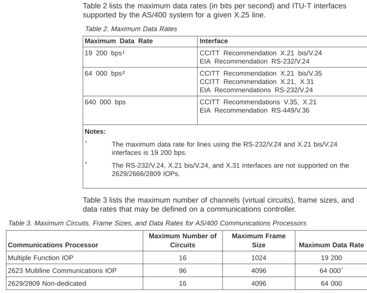
AS/400 X.25 Capabilities
Table 2 lists the maximum data rates (in bits per second) and ITU-T interfaces supported by the AS/400 system for a given X.25 line.
Table 2. Maximum Data Rates
Maximum Data Rate Interface
19 200 bps¹ CCITT Recommendation X.21 bis/V.24 EIA Recommendation RS-232/V.24 64 000 bps² CCITT Recommendation X.21 bis/V.35
CCITT Recommendation X.21, X.31 EIA Recommendations RS-232/V.24 640 000 bps CCITT Recommendations V.35, X.21 EIA Recommendation RS-449/V.36 Notes: ¹
The maximum data rate for lines using the RS-232/V.24 and X.21 bis/V.24 interfaces is 19 200 bps.
² The RS-232/V.24, X.21 bis/V.24, and X.31 interfaces are not supported on the
2629/2666/2809 IOPs.
Table 3 lists the maximum number of channels (virtual circuits), frame sizes, and data rates that may be defined on a communications controller.
Table 3. Maximum Circuits, Frame Sizes, and Data Rates for AS/400 Communications Processors
Communications Processor
Maximum Number of Circuits
Maximum Frame
Size Maximum Data Rate
Multiple Function IOP 16 1024 19 200
2623 Multiline Communications IOP 96 4096 64 000¹
2629/2809 Non-dedicated 16 4096 64 000 | | | | |||||
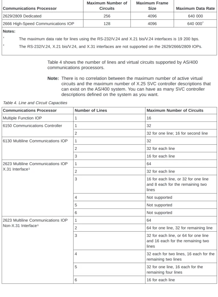
Table 3. Maximum Circuits, Frame Sizes, and Data Rates for AS/400 Communications Processors (continued)
Communications Processor
Maximum Number of Circuits
Maximum Frame
Size Maximum Data Rate
2629/2809 Dedicated 256 4096 640 000
2666 High-Speed Communications IOP 128 4096 640 000²
Notes: ¹
The maximum data rate for lines using the RS-232/V.24 and X.21 bis/V.24 interfaces is 19 200 bps.
² The RS-232/V.24, X.21 bis/V.24, and X.31 interfaces are not supported on the 2629/2666/2809 IOPs.
Table 4 shows the number of lines and virtual circuits supported by AS/400 communications processors.
Note: There is no correlation between the maximum number of active virtual
circuits and the maximum number of X.25 SVC controller descriptions that can exist on the AS/400 system. You can have as many SVC controller descriptions defined on the system as you want.
Table 4. Line and Circuit Capacities
Communications Processor Number of Lines Maximum Number of Circuits
Multiple Function IOP 1 16
6150 Communications Controller 1 32
2 32 for one line; 16 for second line
6130 Multiline Communications IOP 1 32
2 32 for each line
3 16 for each line
2623 Multiline Communications IOP X.31 Interface¹
1 64
2 32 for each line
3 16 for each line, or 32 for one line
and 8 each for the remaining two lines
4 Not supported
5 Not supported
6 Not supported
2623 Multiline Communications IOP Non-X.31 Interface¹
1 64
2 64 for one line, 32 for remaining line
3 32 for each line, or 64 for one line
and 16 each for the remaining two lines
4 32 each for two lines, 16 each for the
remaining two lines
5 32 for one line, 16 each for the
remaining four lines
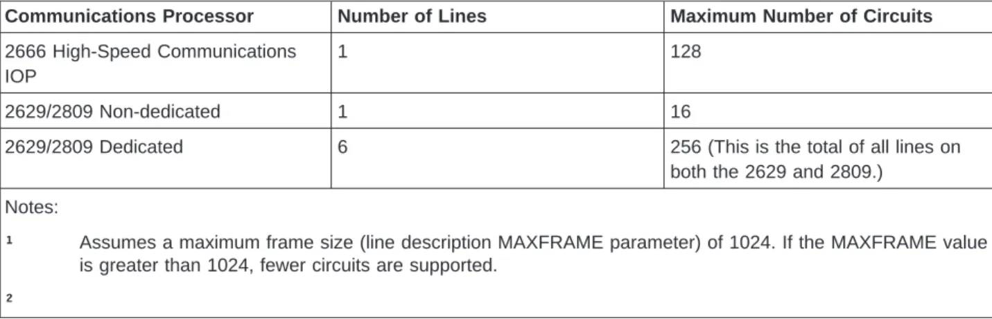
Table 4. Line and Circuit Capacities (continued)
Communications Processor Number of Lines Maximum Number of Circuits
2666 High-Speed Communications IOP
1 128
2629/2809 Non-dedicated 1 16
2629/2809 Dedicated 6 256 (This is the total of all lines on
both the 2629 and 2809.) Notes:
¹ Assumes a maximum frame size (line description MAXFRAME parameter) of 1024. If the MAXFRAME value is greater than 1024, fewer circuits are supported.
²
For more information about the number of lines and the aggregate speed supported by each controller, see theCommunications Managementbook.
X.25 Line Description Configuration Considerations
An X.25 line description describes the X.25 interface between the AS/400 DTE and the data circuit-terminating equipment (DCE) in the network. A major portion of this interface depends on the actual subscription contracted with the network supplier. An X.25 line description can also describe the X.25 interface between an AS/400 DTE, acting as a DCE, and another system acting as a DTE. In this case, there is no X.25 network. Configuration considerations for the AS/400 system are discussed in “Connecting Systems without an X.25 Network (DTE-to-DTE)” on page 20. All SNA AS/400 controller descriptions that are created and attached to a synchronous data link control (SDLC) line can also be attached to a X.25 line. Asynchronous communications controllers can be attached to a X.25 line if the corresponding remote DTE is either an asynchronous communications host system or is attached to a packet assembler/disassembler (PAD) facility. TCP/IP, OSI, IPX, and user-defined connections can be established with remote DTEs that support this type of connection. The X.25 portion of these controller descriptions describes the run-time characteristics of the associated virtual circuit, and for SNA, logical link control (LLC) parameters are provided to allow the logical link station characteristics to be tailored.
The following sections discuss the capabilities, limitations, and values you should be aware of when configuring X.25 lines on your system.
Network Subscription Considerations (DTE-to-DCE)
For describing the interface between a DTE (your AS/400 system, in this case) and a DCE (when the DCE is in an X.25 PSDN), most of the X.25 line description parameters depend on the following information being provided by your network supplier:
DCE clocking rate
If the physical interface (INTERFACE) parameter is not *X31, then this specifies the value to be used in the line speed (LINESPEED) parameter of
| |||| ||| | | | | | | | | | | | | |
the line description. See Table 2 on page 14 for the maximum data rates supported by the AS/400 system over the varying ITU-T physical interfaces.
DTE local network address
The value to be used in the local network address (NETADR) parameter of the line description. This address can be 1 to 15 decimal digits.
If your network subscription includes the type of address/numbering plan identification address subscription facility, however, this address can be up to 17 decimal digits. If this facility is subscribed, the first digit is the type of address subfield, and the second digit is the numbering plan Identification subfield.
Logical channel configuration
Information for each logical channel subscribed to in your network subscription includes:
v The logical group and channel numbers.
v The type of logical channel circuit being used (a permanent or switched virtual circuit, abbreviated as PVC or SVC). For SVCs, this includes whether it supports incoming calls, outgoing calls, or both.
v When a PVC is used, the remote DTE to which data over this logical channel is to be routed to and from the network.
With this information, you can specify all the logical channel entries on the logical channel entries (LGLCHLE) parameter in the X.25 line description. For the type of each logical channel circuit (or virtual circuit), you specify one of the following values: *PVC, *SVCIN, *SVCBOTH, or *SVCOUT. Given the PVC routing information, you can correctly associate the PVC controller descriptions with their corresponding PVC logical channels. When more than one type of virtual circuit is specified in the LGLCHLE parameter, all of the entries for each type should be grouped together. For more information about entering logical channel entries in the X.25 line description, see the description of this parameter in theCommunications
Configurationbook.
Physical interface provided
The value to be used for the physical interface (INTERFACE) parameter of the line description.
HDLC link-level modulus
For high-level data link control (HDLC), the AS/400 system supports a frame link-level modulus of 8; this value cannot be configured.
HDLC link-level maximum send and receive window size
The AS/400 system supports an HDLC maximum send and receive window size of 7; this value cannot be configured.
Maximum and default send and receive packet sizes
The AS/400 system supports the maximum packet size limit of 1024 bytes or 4096 bytes for the AS/400 system, depending on the communications controller being used. For supported configurations, see Table 3 on page 14 . Separate transmit and receive values (independent from each other) can be specified in the packet size parameters. These values are specified in the maximum packet size (MAXPKTSIZE) parameter in the line description, and should be greater than or equal to the corresponding values specified in the default packet size (DFTPKTSIZE) parameter. This default packet size value is used for all logical channels defined for an X.25 line. If a
different value is supplied in a controller description or in the OSI or user-defined configuration, that value will be used on the associated logical channel.
Packet-level modulus
The value to be used in the modulus (MODULUS) parameter of the line description. Allowed values are 8 and 128.
Default packet-level send and receive window size
The values to be used in the default window size (DFTWDWSIZE) parameter of the line description. Separate transmit and receive values (independent from each other) can be specified in the default window size parameter. Packet-level window size specifies the maximum number of unacknowledged packets that can be outstanding at a given time. Values 1 through 7 are valid if MODULUS(8) is specified; values 1 through 15 are valid if MODULUS(128) is specified. The default value is 2. This window size is used for all logical channels on an X.25 line. If a different value is supplied in a controller description, or in the OSI or user-defined
configuration, that value is used on the associated logical channel.
DCE processing overhead and spreading delay of medium to network
These values for either satellite or communications lines, together with the line speed and maximum packet size, are used to determine the idle timer (IDLTMR) parameter value in the line description. For example:
IDLTMR ≥ (2*p + (MAXPKTSIZE*8)/LINESPEED + o) * 10 where:
p = Propagation delay of medium to network (in seconds). For ground lines,p is usually unimportant; for satellites,pcan be significant.
o = DCE processing overhead (in seconds).
See the Communications Configurationbook for the acceptable idle timer values for various combinations of line speeds and packet sizes.
Quality of the communications line to the network
Depending on the line quality (the amount of noise on the X.25 line), the value in the frame retry (FRAMERTY) parameter of the line description can be adjusted. Larger values can allow
transparent recovery (to the application program) on a given line during a particularly noisy period. However, too large a value lengthens error reporting time for permanent errors.
Insertion of local network address by the network
Indicates whether it is necessary for the AS/400 system to insert its local network address into every call request and call accept packet. If *YES (the default) is specified in the insert network address in the packets (ADRINSERT) parameter of the X.25 line description, the AS/400 system inserts its local network address in all call request and call accept packets transmitted on the line.
Level of network support available
Specifies whether the network supports the ITU-T X.25
Recommendation at the 1980, 1984, or 1988 levels. This value is required for the X.25 network level (NETLVL) parameter when creating SNA controller descriptions.
X.25 Switched Line Considerations
CCITT Recommendation X.32 defines the use of X.25 lines in a switched environment. By using switched lines, a system without a nonswitched line connection to a PSDN uses a modem to dial a remote DCE or the PSDN. The system can either dial a public-switched telephone network, or use an ISDN to gain switched access.
The recommendation also defines procedures for identifying the DTE to the network for billing and security reasons. The AS/400 system supports identification to an ISDN by the calling party number, the called party number, and the subaddress provided by the system. The AS/400 system also supports identification of DTEs by the network user identification (NUI) subscription facility.
If a switched physical line is used to connect the AS/400 system to the network by specifying CNNTYPE(*SWTPP), the following considerations must be made:
Physical interface (INTERFACE parameter)
Switched connections are supported for the following interfaces only: v *RS232V24
v *X21BISV24 v *X21BISV35 v *X31
Note: Switched connections are not allowed on the 2666 High-Speed
Communications IOP.
Manual or automatic dial (AUTODIAL parameter)
The call can be established manually or automatically. Automatic dial is accomplished by using an automatic call unit (AUTOCALL(*YES)) or by using a V.25 bis-compatible modem (DIALCMD(*V25BIS)). This parameter does not apply for switched lines on an ISDN.
Automatic call unit (AUTOCALL parameter)
Automatic dialing can be performed using an automatic call unit. Duplex modems are required to use X.25, while most modems requiring automatic call units are half-duplex. This parameter does not apply for switched lines on an integrated services digital network (ISDN) or X.21.
Connection number (CNNNBR parameter)
The connection number specifies the telephone number of the remote DCE to be dialed if automatic dial or an automatic call unit is being used. This parameter does not apply for switched lines on an ISDN.
Call immediate (CALLIMMED parameter)
The call immediate parameter specifies whether the AS/400 system is to call the network immediately when the line is varied on. This parameter should be used when the network does not support dialing the AS/400 system and when the remote DTEs may initiate connections (through SVCs) with the AS/400 system.
Generally, the switched disconnect (SWTDSC) parameter should be *NO when the call immediate parameter is specified as *YES.
Switched disconnect (SWTDSC parameter)
The switched disconnect parameter specifies that the switched line should be disconnected when no virtual circuits are active on the line. The
| | | | | |
time the line must be connected and the time to wait before switched disconnection. The minimum amount of time the switched line will be connected is:
minimum connect timer + disconnection delay timer
The default value for the switched disconnect timer is170 0. Each time a switched line is connected, the connection is maintained for 170 seconds, even if there are no active virtual circuits on the line. If active virtual circuits exist after 170 seconds, the connection is maintained until all virtual circuits become inactive, at which time the switched line is immediately
disconnected.
Note: In some countries, the public switched telephone networks restrict
the length of time that a voice-grade line can be left connected with no activity on the line. The SWTDSCTMR parameter values may have to be reduced to meet these requirements.
Disconnect timers of (0,0) can be specified; however, this is not
recommended because there is not enough time for an incoming SVC to be established before the physical link is disconnected.
If switched disconnection is specified for a line, all active SVCs must be disconnected before the disconnection delay timer starts. For more information on SVC disconnections, see the disconnect timer (DSCTMR) and switched disconnect timer (SWTDSC) parameters in the
Communications Configuration book.
Network user identification (NETUSRID parameter)
Many networks use the network user identification (NUI) on switched lines for accounting and identification purposes. Contact your network
administrator for more information on NUIs. If the NETUSRID parameter is specified, the system encodes the NUI facility on every X.25 call request initiated on the line.
The remaining line description parameters do not depend on your network subscription.
Connecting Systems without an X.25 Network (DTE-to-DTE)
As described earlier, you can connect your AS/400 system to a DTE without going through an X.25 network. Modems, modem eliminators, or an ISDN may provide the physical connection. When this method is used, the AS/400 system acts as a DCE to the remote DTE, and the remote DTE acts as though it is attached to an X.25 network (even though it is not). The remote DTE in this example could be a System/36, System/38, or another AS/400 system. When configuring an AS/400 DCE in this manner, the following considerations apply:
X.25 DCE support (X25DCE parameter)
The AS/400 system should normally specify *YES for the X25DCE parameter in the line description.
The value *NEG can be specified for switched connections when the remote system supports the DTE/DCE role negotiation feature (another AS/400 system, for example). *NEG allows the two systems to negotiate their roles, with one system being selected as the DCE, the other as DTE. *NEG should be specified only when the remote system supports this
Connection initiation (CNNINIT parameter)
In the DCE line description, specifying *LOCAL for the CNNINIT parameter causes infinite polling of the remote DTE. When *LOCAL is specified, the remote DTE system must specify *NO for X.25 DCE support and specify either *WAIT or *REMOTE for its CNNINIT parameter, or their equivalent values for non-AS/400 systems.
For switched lines, *CALLER can be specified for the CNNINIT parameter. This value instructs the AS/400 system to determine which system initiates the call, based on the direction of the call. *CALLER should only be specified when the remote system supports this feature and is configured with an equivalent value.
With each line configured as described, either line can be varied on first. The remote system waits for the local system to contact it. If the local system has X.25 DCE support and CNNINIT(*LOCAL) for connection initiation, it will poll the remote system indefinitely or until the remote system responds. Vary the line off if you do not want to establish a connection.
Matching logical channel tables (LGLCHLE parameter)
The logical channel identifiers and types that are specified on the LGLCHLE parameter should match between the AS/400 DCE and the directly attached DTE. For SVCs, this is possible because the channel ordering with
X25DCE(*YES) is *SVCOUT, *SVCBOTH, and *SVCIN.
Insert network address into packets (ADRINSERT parameter)
If SVCs are used when connecting an AS/400 system as a DCE without a network to another DTE, both systems must specify ADRINSERT as *YES (or its equivalent) in the line description.
Chapter 3. End-to-End Connectivity Considerations
Just as an X.25 line description describes the interface between data terminal equipment (DTE) and data circuit-terminating equipment (DCE), AS/400 system controller descriptions describe characteristics of remote DTEs. This chapter discusses the controller descriptions and values unique to the X.25 line.
X.25-Specific Values
Several of the values in the controller descriptions are unique to X.25 and depend on the network subscription information. For each of the remote DTEs with which your AS/400 system is communicating, you must determine certain characteristics and configure them in the associated controller descriptions.
Regardless of whether the AS/400 system is connected to the remote DTE through a packet-switching data network (PSDN) or connected directly through a modem eliminator, the remote considerations in this topic are the same. The following characteristics about the remote DTEs determine some of the X.25-specific values for the controller description parameters:
Note: These characteristics are not applicable for users of a network controller,
such as Transmission Control Protocol/Internet Protocol (TCP/IP), open systems interconnection (OSI), Internetwork Packet Exchange (IPX), or user-defined communications.
Type of virtual circuit
Specify whether the connection to the remote DTE is by a permanent virtual circuit (PVC) or a switched virtual circuit (SVC). Your choice of either a PVC or an SVC should be determined by cost and use. The type of virtual circuit is determined by the logical channel entry (LGLCHLE) parameter on the X.25 line description. See “PVC Functions” on page 24 or “SVC Functions”
on page 24 for more information about PVCs or SVCs.
Closed user group identifier of remote DTE
An AS/400 system can call a remote DTE that is subscribed to a closed user group in the network. The value for the initial connection (INLCNN) parameter on the controller description must be *DIAL. The X.25 user group identifier (USRGRPID) parameter in the SVC controller description must match the user group identifier assigned by the network to the remote DTE.
Billing intentions
An AS/400 system normally does not request or accept reverse charging.
Reverse charging allows the data terminal equipment (DTE) to request
that the cost of a communications session be charged to the DTE that is called.
However, the AS/400 system can be configured to request X.25 reverse charging (RVSCRG parameter on the controller description) on outgoing calls, to accept reverse charging on incoming calls, or both. You must determine the type of billing policy to be used for virtual calls to correctly configure your system to handle reverse charging. Reverse charging applies to SVCs only.
Additional user facilities to be requested
The AS/400 system allows you to request additional network user facilities (besides closed user group, reverse charging, and packet or window size
| | | | |
the user facility (USRFCL parameter) field of controller descriptions. If the network user identification parameter (NETUSRID) is specified in the line description, the network user identification (NUI) facility is encoded and joined with the facilities listed in the USRFCL parameter of the controller description. The joined NUI facility is then placed in the facility field of CALL REQUEST packets. User facilities apply to SVCs only.
The remaining controller description parameters are dependent on the protocol that is being used on each of the X.25 virtual circuits defined for a line description. See “AS/400-Supported Protocols on an X.25 Virtual Circuit” on page 33 for more information about the higher layer protocols that can be used with AS/400 X.25 communications. The following discussions provide a general overview of using X.25 PVCs and SVCs on the AS/400 system.
PVC Functions
PVCs are defined in the line description and may be attached to a controller description. If the PVCs are defined in the line description and not attached to a specific controller, the PVCs become eligible for any application using the network controller that is attached to the line and varied on.
The virtual circuit is established when requested by an application using the network controller or when the controller assigned to the PVC is varied on.
After a PVC has been defined and established, data is transmitted on that PVC as if it were a nonswitched line. Because no call establishment or completion
procedures are required on a PVC, it is faster to establish PVCs than SVCs. Therefore, when using X.25 DCE-to-DTE communications over nonswitched lines, it is recommended that PVCs be used whenever possible to eliminate SVC overhead. When configuring an X.25 logical channel as a PVC, you must be certain that the configuration parameters that are entered on the AS/400 system match the X.25 network subscription characteristics for that logical channel. Parameters such as packet size, packet window size, and modulus must be coordinated before doing the configuration. In addition, the higher layer protocol to be used on each virtual circuit must be coordinated by the two communicating DTEs. If these parameters do not agree, errors can occur either when the virtual circuit connection is first
established, or in some cases, only after the local AS/400 system, the network, or a remote DTE detects some violation of this agreement.
The AS/400 system does not support PVCs on physically switched X.25 lines.
SVC Functions
The following topics describe some considerations for the three types of SVC functions supported by the AS/400 system. These types are specified on the logical channel entries (LGLCHLE) parameter in the X.25 line description. The SVC types are:
v SVC incoming call (*SVCIN) v SVC outgoing call (*SVCOUT)
On a given switched logical channel, a variety of different higher layer protocols are possible at different times. For example, an SVC may be established using the SNA protocol for a short period of time. After that virtual call is ended, another call can be made on the same logical channel. This time, the asynchronous protocol may be used. Later, the protocol could be TCP/IP, OSI, IPX, or user-defined.
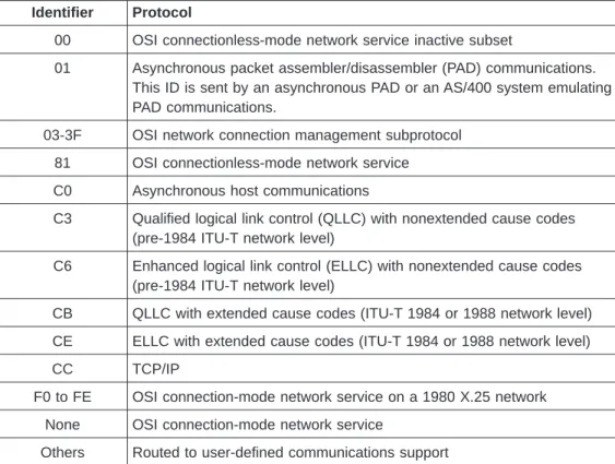
The higher layer protocol of a call is determined by the first byte of the user data field, called the protocol identifier, in the CALL REQUEST packet. Table 5 defines the hexadecimal protocol identifiers supported by the AS/400 system.
Table 5. AS/400-Supported Protocol Identifiers
Identifier Protocol
00 OSI connectionless-mode network service inactive subset
01 Asynchronous packet assembler/disassembler (PAD) communications. This ID is sent by an asynchronous PAD or an AS/400 system emulating PAD communications.
03-3F OSI network connection management subprotocol 81 OSI connectionless-mode network service C0 Asynchronous host communications
C3 Qualified logical link control (QLLC) with nonextended cause codes (pre-1984 ITU-T network level)
C6 Enhanced logical link control (ELLC) with nonextended cause codes (pre-1984 ITU-T network level)
CB QLLC with extended cause codes (ITU-T 1984 or 1988 network level) CE ELLC with extended cause codes (ITU-T 1984 or 1988 network level)
CC TCP/IP
F0 to FE OSI connection-mode network service on a 1980 X.25 network None OSI connection-mode network service
Others Routed to user-defined communications support
SNA protocol identifiers are derived from the X.25 link protocol (LINKPCL) and X.25 network level (NETLVL) parameters of the controller description for outgoing calls. Incoming calls are screened according to the same parameters. Asynchronous protocol identifiers are derived according to the PAD emulation (PADEML) parameter of the asynchronous controller description. TCP/IP calls always use a protocol identifier of hex CC.
The AS/400 system allows for security when connecting to an X.25 packet-switched network by screening incoming calls according to fields in an INCOMING CALL packet. Access to an AS/400 system from the X.25 network through any SVC is controlled by the calling DTE network address, together with the protocol identifier and password (SNA only), all of which are located in the 12-byte user data field of an X.25 INCOMING CALL packet.
Table 6 on page 26 shows the format of the user data field for SNA and
asynchronous calls. Note that this field, other than the protocol identifier, will be different for incoming calls associated with TCP/IP, OSI, IPX, and user-defined communications. | | | | | | | | |
Table 6. User Data Fields for an SNA and Asynchronous CALL REQUEST Packet
Byte Number
Length
(Bytes) Description of User Data Field
0 1 Protocol identifier. See Table 5 on page 25 for a list of possible values.
1 1 Password indicator. Possible hexadecimal values are:
00 No password was sent.
01 A password follows.
2 1 Call or recall indicator, used by ELLC only. Possible hexadecimal values are:
00 Initial call (all non-SNA protocols).
01 Recall to establish a broken connection.
3 1 Reserved (set to 00).
4 8 X.25 network password (SNA only), taken from the X.25 connection password (CNNPWD) parameter of the controller description used for an SVC outgoing call or recall. If the password is less than 8 characters, it is left-justified and padded with blanks.
Before a connection can be completed for SVC incoming calls, the password sent by the remote DTE in the incoming call or recall packet must match the password specified in the controller description that describes that remote DTE. Blank or *NONE indicates that a password will not be used; the network password field contains blanks.
Figure 6 illustrates user data formats for a CALL REQUEST packet, created and accepted by the AS/400 system when either no value or *NONE is specified for the CNNPWD parameter of the associated SNA controller description. The CNNPWD parameter contains blanks if a create controller description command is used without specifying this parameter. The CNNPWD parameter contains *NONE if the change controller description command is used. These two values are equivalent.
Byte: 01234
Created for *NONE: pi 01 ci 00 4040404040404040 Accepted as *NONE: pi 01 ci 00 4040404040404040
pi 00 ci 00 pi 00 ci pi 00 pi
pi SNA protocol identifier
ci Call (or recall) indicator
In the cases where a password is not supplied in the call data, the AS/400 system creates its equivalent of an *NONE password, which is eight blanks (hex
4040404040404040), as shown in Figure 6 on page 26. If this password is used and no corresponding controller is found, the call is rejected and a message is displayed to the local system operator, indicating an incoming call with a password of eight blanks was rejected.
SVC Incoming Call Function
For a flowchart of the control and routing of incoming calls, see the diagram in Figure 7 on page 28.
X.25 calls arriving to the AS/400 system are routed by the X.25 support, based primarily on the protocol ID field. Protocol IDs are defined for and used by SNA, asynchronous X.25, OSI, and TCP/IP protocols. Other protocol IDs can be defined and used by applications that use user-defined communications support. For a list of protocol identifiers supported by communications subsystems on the AS/400 system, see Table 5 on page 25.
If the protocol ID field contains an SNA or asynchronous X.25 protocol ID, the system attempts to route the incoming call to the appropriate controller for SNA or asynchronous X.25 support. Incoming calls are further screened based on the calling network address and, for the SNA protocol, the password field in the call user data. A controller must be configured with a matching calling network address (or *ANY) and connection password. The controller must also contain the X.25 line description name in its switched line list.
If there is no switched vary on pending SNA or asynchronous X.25 controller to accept the call, the system routes the call to the network controller, if present. If the protocol ID is not an SNA or asynchronous X.25 protocol ID, the system also routes the call to the network controller. If there is no network controller, the call is cleared. Each line description may have only one network controller.
Each network controller on the AS/400 system defines one or more virtual circuits through an X.25 packet-switching data network (PSDN). The virtual circuits defined by a network controller can be used for TCP/IP, user-defined, IPX, or OSI
communications.
| | | |
Incoming Call Function for SNA/Asynchronous
The SVC incoming call (*SVCIN) function for SNA or asynchronous incoming calls is similar to an automatic answer function. It includes the automatic answering of calls received on any one of the lines specified in the switched-line list
(SWTLINLST) parameter of the controller description. The AS/400 system must be prepared to respond to an incoming call.
On the logical channel entry (LGLCHLE) parameter of the Create X.25 Line
(CRTLINX25) or the Change X.25 Line (CHGLINX25) command, at least one logical channel entry must be configured as either *SVCIN or *SVCBOTH and cannot already be in use on the active X.25 line. The associated controller description must