T-Check in System-of-Systems
Technologies: Cloud Computing
Harrison D. Strowd Grace A. Lewis
September 2010
TECHNICAL NOTE CMU/SEI-2010-TN-009
Research, Technology, and System Solutions (RTSS) Program Unlimited distribution subject to the copyright.
This report was prepared for the SEI Administrative Agent ESC/XPK
5 Eglin Street
Hanscom AFB, MA 01731-2100
The ideas and findings in this report should not be construed as an official DoD position. It is published in the interest of scientific and technical information exchange.
This work is sponsored by the U.S. Department of Defense. The Software Engineering Institute is a federally funded research and development center sponsored by the U.S. Department of Defense.
Copyright 2010 Carnegie Mellon University. NO WARRANTY
THIS CARNEGIE MELLON UNIVERSITY AND SOFTWARE ENGINEERING INSTITUTE MATERIAL IS FURNISHED ON AN "AS-IS" BASIS. CARNEGIE MELLON UNIVERSITY MAKES NO WARRANTIES OF ANY KIND, EITHER EXPRESSED OR IMPLIED, AS TO ANY MATTER INCLUDING, BUT NOT LIMITED TO, WARRANTY OF FITNESS FOR PURPOSE OR MERCHANTABILITY, EXCLUSIVITY, OR RESULTS
OBTAINED FROM USE OF THE MATERIAL. CARNEGIE MELLON UNIVERSITY DOES NOT MAKE ANY WARRANTY OF ANY KIND WITH RESPECT TO FREEDOM FROM PATENT, TRADEMARK, OR
COPYRIGHT INFRINGEMENT.
Use of any trademarks in this report is not intended in any way to infringe on the rights of the trademark holder. Internal use. Permission to reproduce this document and to prepare derivative works from this document for internal use is granted, provided the copyright and "No Warranty" statements are included with all reproductions and derivative works.
External use. This document may be reproduced in its entirety, without modification, and freely distributed in written or electronic form without requesting formal permission. Permission is required for any other external and/or commercial use. Requests for permission should be directed to the Software Engineering Institute at [email protected].
This work was created in the performance of Federal Government Contract Number FA8721-05-C-0003 with Carnegie Mellon University for the operation of the Software Engineering Institute, a federally funded research and development center. The Government of the United States has a royalty-free government-purpose license to use, duplicate, or disclose the work, in whole or in part and in any manner, and to have or permit others to do so, for government purposes pursuant to the copyright license under the clause at 252.227-7013.
Table of Contents
Acknowledgements vii
Abstract ix
1 Introduction 1
1.1 Cloud Computing 1
1.2 Types of Cloud Computing 2
1.3 Drivers and Barriers to Cloud Computing Adoption 5
2 Using the T-Check Method 7
2.1 T-Check Context 8
2.2 Develop Hypotheses 8
2.3 Develop Criteria 9
3 Designing and Implementing the Solution 10
3.1 Defining the Initial System Architecture Based on the T-Check Context 10
3.2 Defining the System Architecture for Testing Hypothesis 1 13
3.2.1 Dynamic View of the Solution for Testing Hypothesis 1 13
3.2.2 Deployment View of the Solution for Testing Hypothesis 1 16
3.2.3 Defining the Resource Manager’s Behavior 18
3.3 Defining the System Architecture for Testing Hypothesis 2 20
3.3.1 Dynamic View of the Solution for Testing Hypothesis 2 20
3.3.2 Deployment View of the Solution for Testing Hypothesis 2 22
3.4 Defining the System Architecture for Testing Hypothesis 3 24
3.4.1 Dynamic View of the Solution for Testing Hypothesis 3 25
3.4.2 Deployment View of the Solution for Testing Hypothesis 3 27
3.5 Selecting Cloud Computing Providers 30
3.6 Implementing the T-Check Solutions 32
3.6.1 Implementing the Solution for Testing Hypothesis 1 32
3.6.2 Implementing the Solution for Testing Hypothesis 2 33
3.6.3 Implementing the Solution for Testing Hypothesis 3 33
4 Evaluation and Experiences with Cloud Computing 34
4.1 Results for Hypothesis 1 34
4.1.1 Effects of Domain Experience 35
4.1.2 IaaS vs. PaaS 35
4.2 Results for Hypothesis 2 36
4.2.1 Scaling Resources with Google App Engine 36
4.2.2 Scaling Resources with Force.com 37
4.2.3 Scaling Resources with Amazon Web Services 37
4.3 Results for Hypothesis 3 38
5 Conclusions and Open Questions 40
List of Figures
Figure 1: T-Check Process for Technology Evaluation 7
Figure 2: Module View of the Initial System 11
Figure 3: Component and Connector View of the Solution for Testing Hypothesis 1 14
Figure 4: Deployment View of the Solution for Testing Hypothesis 1 16
Figure 5: Sequence Diagram for a Search Request when Internal Resources Are
at Their Maximum Usage Threshold 18
Figure 6: Sequence Diagram for a Search Request when Internal Resources Are Not
at Their Maximum Usage Threshold 19
Figure 7: Sequence Diagram for Servicing a Create or Update Request 19
Figure 8: Component and Connector View of the Solution for Testing Hypothesis 2 20
Figure 9: Deployment View for the Solution for Testing Hypothesis 2 23
Figure 10: Component and Connector View of the Solution for Testing Hypothesis 3 25
List of Tables
Table 1: Examples of Cloud Computing Providers by Type 3
Table 2: Drivers for Cloud Computing Adoption 5
Table 3: Barriers to Cloud Computing Adoption 6
Table 4: Criteria Used to Evaluate the Hypotheses 9
Table 5: Element Responsibilities for the Module View of the Initial System 11 Table 6: Relationship Responsibilities for the Module View of the Initial System 13 Table 7: Element Responsibilities for the Component and Connector View of the
Solution for Testing Hypothesis 1 14
Table 8: Relationship Responsibilities for the Component and Connector View of the
Solution for Testing Hypothesis 1 15
Table 9: Element Responsibilities for the Deployment View of the Solution for
Testing Hypothesis 1 17
Table 10: Relationship Responsibilities for the Deployment View of the Solution for
Testing Hypothesis 1 17
Table 11: Element Responsibilities for the Component and Connector View of the
Solution for Testing Hypothesis 2 21
Table 12: Relationship Responsibilities for the Component and Connector View of the
Solution for Testing Hypothesis 2 22
Table 13: Element Responsibilities for the Deployment View of the Solution for
Testing Hypothesis 2 23
Table 14: Relationship Responsibilities for the Deployment View of the Solution for
Testing Hypothesis 2 24
Table 15: Element Responsibilities for the Component and Connector View of the
Solution for Testing Hypothesis 3 25
Table 16: Relationship Responsibilities for the Component and Connector View of the
Solution for Testing Hypothesis 3 27
Table 17: Element Responsibilities for the Deployment View of the Solution for
Testing Hypothesis 3 28
Table 18: Relationship Responsibilities for the Deployment View of the Solution for
Testing Hypothesis 3 29
Table 19: Initial Survey of Cloud Computing Providers 30
Table 20: Results of Initial Cloud Computing Providers Evaluation 31
Table 21: Time to Develop the Solution for Testing Hypothesis 1 34
Table 22: Code Modifications Required for the Solution for Testing Hypothesis 1 35 Table 23: Time Requirements to Develop the Solution for Testing Hypothesis 3 38 Table 24: Code Modifications Required for Modifying the AWS Calendar to Use
Acknowledgements
The authors would like to thank Carnegie Mellon University’s Master of Science in Information Technology - Software Engineering (MSIT-SE) program for co-sponsoring the independent study that resulted in this report, as well as Carnegie Mellon® Software Engineering Institute colleagues John Klein and Marc Novakouski for their valuable technical reviews.
®
Abstract
This technical note presents the results of applying the T-Check method in an initial investigation of cloud computing. In this report, three hypotheses are examined: (1) an organization can use its exist-ing infrastructure simultaneously with cloud resources with relative ease; (2) cloud computexist-ing envi-ronments provide ways to continuously update the amount of resources allocated to an organization; and (3) it is possible to move an application’s resources between cloud computing providers, with va-rying levels of effort required. From the T-Check investigation, the first hypothesis is partially sus-tained and the last two hypotheses are fully sussus-tained within the context specified for the investiga-tion.
From an engineering perspective, cloud computing is a distributed computing paradigm that focuses on providing a wide range of users with distributed access to virtualized hardware and/or software infrastructure over the internet. From a business perspective, it is the availability of computing re-sources that are scalable and billed on a usage basis. While scalability is the primary tenet of cloud computing, a host of other advantages are advertised as being inherently obtained through cloud com-puting.
1 Introduction
Cloud computing is an emerging paradigm that focuses on providing dynamic, on-demand scalability of virtualized hardware and/or software resources to a diverse set of users. While scalability is the primary tenet of cloud computing, a host of other advantages are advertised as being inherently ob-tained through cloud computing. The purpose of this report is to apply the T-CheckSM method to ex-amine a set of claims about cloud computing adoption.
A T-Check investigation is a simple and cost-effective way to understand and evaluate the claims made about a technology in a given context [Lewis 2005]. Specifically, this T-Check investigation focuses on finding initial answers to the following questions:
1. How difficult is it for an organization to use existing internal resources simultaneously with cloud resources?
2. What mechanisms are provided for users to update their resource allocations dynamically? 3. How difficult is it to move an application from one cloud provider to another?
The rest of this section will provide a brief introduction to cloud computing and related technologies. Section 2 presents the context for the T-Check investigation and how the above questions were ad-dressed. Section 3 describes the solutions employed to evaluate the proposed hypotheses, and Section 4 presents the results of the evaluation. Section 5 discusses plans for future work in this area and brief-ly presents the conclusions reached in this experimental setting.1
1.1 Cloud Computing
Cloud computing is an emerging technology that has sparked the interest of a wide range of organiza-tions. In general, cloud computing is a distributed computing paradigm that focuses on providing a wide range of users with distributed access to scalable, virtualized hardware and/or software infra-structure over the internet.
Many definitions have been offered for this term. According to Foster and colleagues, cloud compu-ting is
a large-scale distributed computing paradigm that is driven by economies of scale, in which a pool of abstracted, virtualized, dynamically-scalable, managed computing power, storage, platforms, and services are delivered on demand to external customers over the internet [Foster 2008]. McEvoy and Schulze define it as ―a style of computing where massively scalable IT-related capabili-ties are provided as a service across the Internet to multiple external customers‖ [McEvoy 2008]. Er-dogmus provides a concise definition by saying ―Cloud computing is an emerging computational model in which applications, data, and IT resources are provided as services to users over the Web‖ [Erdogmus 2009].
SM
T-Check is a service mark of Carnegie Mellon University.
1
A large part of this work was performed as an independent study in Carnegie Mellon University’s Master of Science in Information Technology – Software Engineering (MSIT-SE) program.
1.2 Types of Cloud Computing
Cloud computing implementations can be characterized in two orthogonal ways: (1) by the capabili-ties they provide and (2) by who can access their resources. Based on capabilicapabili-ties, there are three types of cloud computing implementations:
1.Infrastructure as a Service (IaaS)
This is mainly computational infrastructure available over the internet, such as compute cycles and storage, which can be utilized in the same way as internally owned resources. IaaS providers en-force minimal restrictions on their users2 to allow them maximum control and configuration of the resources. These resources typically provide a variety of interfaces to facilitate interaction, and there are usually additional services provided, such as query services for storage resources. From the user’s perspective, these resources appear to be identical to resources that are owned, op-erated, and maintained by the organization. The key difference is that users pay only for the band-width, computation, and storage that they use. If at any time the resources are no longer needed, they can potentially be terminated without incurring any additional costs. This removes the large upfront cost associated with acquiring hardware resources, and the scalability of such resources al-lows users to handle variability in their application’s usage, paying for the extra resources only when they are required.
2.Platform as a Service (PaaS)
PaaS refers to application development platforms—hardware and software components—that ena-ble users to leverage the resources of established organizations to create and host applications of a larger scale than an individual or a small organization would be able to handle. Services include, but are not limited to, software installation and configuration, resource scaling, and platform main-tenance and upgrading. In order to enable these services, the provider places restrictions on the user by specifying various aspects of the platform, such as the programming languages supported, data storage mechanisms, and resource monitoring capabilities. In this model, user organizations use re-sources from the cloud and deploy their applications in the cloud as well.
From the user’s perspective, these providers offer significant functionality out-of-the-box. The key requirements for deploying an application into such an environment are to ensure that the selected platform will support the application and that the services offered meet the needs of the user. When these key criteria align, the user is able to leverage a significant amount of functionality with poten-tially very little effort.
3.Software as a Service (SaaS)
SaaS focuses on providing users with business-specific capabilities—hardware and software appli-cations. In general, SaaS is a model of software deployment in which a provider licenses an applica-tion to user organizaapplica-tions for use as a service on demand. However, there is a wide spectrum of what is covered under SaaS, and which parts of SaaS fall under the definition of cloud computing is often debated.
2 The term user will be used throughout the report to refer to the organization (or individual) that acquires resources
from the cloud to be used as part of its IT infrastructure. It does not refer to the end user of the applications that are hosted in the cloud. If this is the case, the term end user will be used. Other terms used by cloud providers and re-searchers to refer to user organizations include consumer, customer, and tenant.
According to Chong and Carraro, there are multiple levels of SaaS [Chong 2006]:
Level 1: An application is specifically run for one user organization at an SaaS provider, sim-ilar to the traditional ASP (application server provider) model.
Level 2: The SaaS application is customizable via configuration, and one instance of the ap-plication serves only one user organization.
Level 3: The SaaS application is customizable, and a single instance of the SaaS application serves multiple user organizations.
Level 4: The SaaS application is developed as a single instance multi-tenant3 application, and several instances are run in a load-balanced server farm.
From the user organization’s perspective, SaaS enables organizations to use out-of-the-box, busi-ness-specific capabilities developed by third parties instead of acquiring, hosting, and managing large software packages or developing proprietary solutions.
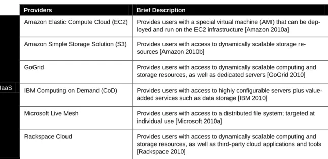
Table 1 shows some examples of the three cloud computing types. For simplicity, we classified pro-viders based on their primary focus.
Table 1: Examples of Cloud Computing Providers by Type4
Providers Brief Description
IaaS
Amazon Elastic Compute Cloud (EC2) Provides users with a special virtual machine (AMI) that can be dep-loyed and run on the EC2 infrastructure [Amazon 2010a]
Amazon Simple Storage Solution (S3) Provides users with access to dynamically scalable storage re-sources [Amazon 2010b]
GoGrid Provides users with access to dynamically scalable computing and storage resources, as well as dedicated servers [GoGrid 2010] IBM Computing on Demand (CoD) Provides users with access to highly configurable servers plus
value-added services such as data storage [IBM 2010]
Microsoft Live Mesh Provides users with access to a distributed file system; targeted at individual use [Microsoft 2010a]
Rackspace Cloud Provides users with access to dynamically scalable computing and storage resources, as well as third-party cloud applications and tools [Rackspace 2010]
3 The term used by SaaS providers to refer to user organizations is tenant. 4
It is difficult to classify providers as purely IaaS, PaaS, or SaaS. For example, the Microsoft Azure Services Platform could be classified as IaaS and PaaS, and Force.com could be classified as PaaS and SaaS. However, for simplicity, the providers are classified based on their primary focus.
Table 1: Examples of Cloud Computing Providers by Type (cont.)
Based on who can access resources, there are two types of cloud computing implementations or dep-loyment models:5
1.Public clouds
In public clouds, resources are offered as a service, usually over an internet connection, for a pay-per-usage fee. Users can scale on demand and do not need to purchase hardware. Cloud providers manage the infrastructure and pool resources into capacity required by its users.
2.Private clouds
Private clouds are typically deployed inside a firewall and managed by the user organization. In this case, the user organization owns the software and hardware running in the cloud, manages the cloud, and provides virtualized cloud resources. These resources are typically not shared outside the organization and full control is retained by the organization. Examples of companies that provide resources for organizations to build private clouds include
3tera: Provides developers with tools to build their own cloud computing infrastructures [3tera 2010]
Eucalyptus Systems: Provides an open-source application that can be used to implement a cloud computing environment on a datacenter. This organization is also trying to establish a set of open standards for cloud computing [Eucalyptus 2010].
5 The National Institute of Standards and Technology (NIST) defines two additional types of cloud deployment models:
(1) community clouds that are shared by multiple organizations and support specific needs and concerns of a com-munity and (2) hybrid clouds that are the combination of two or more public, private, and comcom-munity clouds. Howev-er, both community and hybrid cloud are specialties of public and private clouds and are therefore not included in the discussion. Additional information is available at http://csrc.nist.gov/groups/SNS/cloud-computing/.
Providers Brief Description
PaaS
Akamai EdgePlatform Provides a large distributed computing platform on which organiza-tions can deploy their web applicaorganiza-tions; large focus on analysis and monitoring of resources [Akamai 2010]
Force.com
(from salesforce.com, an SaaS pro-vider)
Provides users a platform to build and run applications and compo-nents bought from AppExchange or custom applications [Salesforce 2010a]
Google App Engine (GAE) Provides users a complete development stack and allows them to run their applications on Google’s infrastructure [Google 2010a] Microsoft Azure Services Platform Provides users with on-demand compute and storage services as
well as a development platform based on Windows Azure [Microsoft 2010b]
Yahoo! Open Strategy (Y!OS) Provides users with a means of developing web applications on top of the existing Yahoo! platform, and in doing so leveraging a signifi-cant portion of the Yahoo! Resources [Yahoo 2010]
SaaS
Google Apps Provides web-based office tools such as e-mail, calendar, and doc-ument management tools [Google 2010b]
Salesforce.com Provides a full customer relationship management (CRM) application [Salesforce 2010b]
Zoho Provides a large suite of web-based applications, mostly for enter-prise use [Zoho 2010]
Ubuntu: Provides server software that can be used to implement scalable, manageable virtual server images [Ubuntu 2010]
1.3 Drivers and Barriers to Cloud Computing Adoption
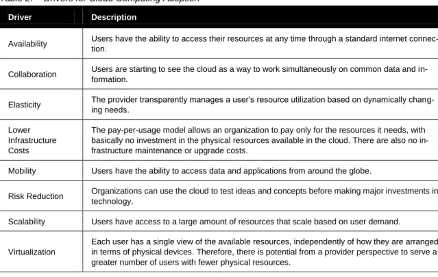
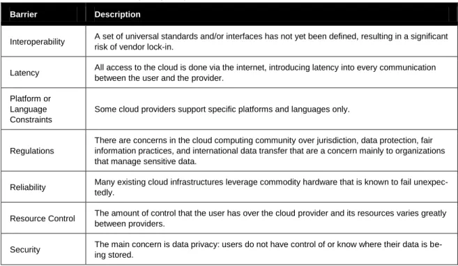
According to Gartner’s Hype Cycle for Emerging Technologies, cloud computing is currently at the ―peak of inflated expectations‖ [Gartner 2009]. One of the primary goals of this study is to better un-derstand the claims being made about cloud computing and whether they accurately depict the tech-nology. In our initial research into cloud computing, we identified a wide range of claims being made about cloud computing adoption. We have classified them as either drivers for or barriers to cloud computing adoption and have documented them in Table 2 and Table 3, respectively. In each table, the entries are listed in alphabetical order.
Some of these claims will be used as input to the study that will be described in the next section.
Table 2: Drivers for Cloud Computing Adoption
Driver Description
Availability Users have the ability to access their resources at any time through a standard internet connec-tion.
Collaboration Users are starting to see the cloud as a way to work simultaneously on common data and in-formation.
Elasticity The provider transparently manages a user’s resource utilization based on dynamically chang-ing needs.
Lower Infrastructure Costs
The pay-per-usage model allows an organization to pay only for the resources it needs, with basically no investment in the physical resources available in the cloud. There are also no in-frastructure maintenance or upgrade costs.
Mobility Users have the ability to access data and applications from around the globe.
Risk Reduction Organizations can use the cloud to test ideas and concepts before making major investments in technology.
Scalability Users have access to a large amount of resources that scale based on user demand.
Virtualization
Each user has a single view of the available resources, independently of how they are arranged in terms of physical devices. Therefore, there is potential from a provider perspective to serve a greater number of users with fewer physical resources.
Table 3: Barriers to Cloud Computing Adoption
Barrier Description
Interoperability A set of universal standards and/or interfaces has not yet been defined, resulting in a significant risk of vendor lock-in.
Latency All access to the cloud is done via the internet, introducing latency into every communication between the user and the provider.
Platform or Language Constraints
Some cloud providers support specific platforms and languages only.
Regulations
There are concerns in the cloud computing community over jurisdiction, data protection, fair information practices, and international data transfer that are a concern mainly to organizations that manage sensitive data.
Reliability Many existing cloud infrastructures leverage commodity hardware that is known to fail unexpec-tedly.
Resource Control The amount of control that the user has over the cloud provider and its resources varies greatly between providers.
Security The main concern is data privacy: users do not have control of or know where their data is be-ing stored.
2 Using the T-Check Method
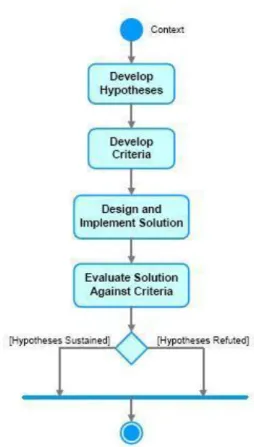
The T-Check method is a context-dependent technique for evaluating technologies. This method in-volves (1) formulating hypotheses about the technology and (2) examining these hypotheses against specific criteria through hands-on experimentation. The outcome of this two-stage method is that the hypotheses are either sustained (fully or partially) or refuted. The T-Check method has the advantage of producing very efficient and representative experiments that not only evaluate technologies in the context of their intended use but also generate hands-on competence with the technologies. A claim can be made that the simplicity of the experiments implies that the results do not scale. However, it can be argued that when the experiments disprove a claim ―in the small,‖ the results could be similar ―in the large‖ or warrant additional experimentation at a larger scale. A graphical representation of the T-Check process is shown in Figure 1.
Figure 1: T-Check Process for Technology Evaluation
The T-Check method is part of a larger process for context-based technology evaluation. In this larger process, the context for the T-Check is established and the expectations from the technology are cap-tured within the context in which they are going to be used, including organizational constraints [Lew-is 2005].
2.1 T-Check Context
The context for this T-Check investigation is a hypothetical organization that has developed and is maintaining a simple calendar application to advertise events that are of interest to the community. Each entry in the calendar consists of an identification number (issued by the system), a title, a date, and event details. The application has three actions that are available to its end users: creating a new entry, updating an existing entry, and searching the entire set of entries.6 Because the calendar is pri-marily used for advertising events that are of interest to many people, the entries in the calendar are created and updated infrequently but are searched frequently. This means that the limiting resource is the compute power required to perform the requested searches.
The organization has been using infrastructure that is owned and operated internally to support its ca-lendar application. Currently, the organization is experiencing rapid growth and its internal resources are no longer sufficient to support its end-user base. At the same time, the organization is constrained by a budget that cannot support the cost required to purchase the machines needed to support peak loads. The organization is highly concerned with stretching its budget and would like to continue to make use of the existing infrastructure as much as possible to reduce overall costs.
While recognizing the need to support the current increase in end users, the organization has plans for growing its applications and expects similar boosts in end-user numbers over the next five years. As a result, the organization’s leaders would like to be prepared to handle similar situations more gracefully in the future. Unfortunately, these events will not always be predictable, requiring the ability to modi-fy the resource allocation dynamically. Based on these factors, the organization feels that cloud com-puting would be an ideal fit. At the same time, the organization realizes that cloud comcom-puting is still considered an emerging technology and is concerned about the possibility of vendor lock-in. The ability to change cloud computing providers, if needed, is an important concern for the organization. In regard to its concerns, the organization would like to answer the following questions about cloud computing:
1. How difficult is it for an organization to run an application using existing internal resources si-multaneously with cloud resources?
2. What mechanisms are provided for users to update their resource allocation dynamically? How frequently can users update their resource allocation (once per second, minute, hour, day, etc.)? What size variance, in terms of resource quantities, is supported for users to update their resource allocation (launching/terminating 1, 10s, 100s, or 1,000s of machines)?
3. How difficult is it to move an application from one cloud provider to another? 2.2 Develop Hypotheses
To answer these questions, we have identified the following hypotheses to be verified or refuted in this study:
1. An organization can deliver an application that uses its existing infrastructure simultaneously with cloud resources, with relative ease.
2. Cloud computing environments provide ways to continuously update the amount of resources allocated to an organization.
6
3. It is possible to move an application's resources from one cloud provider to another, with varying levels of effort required.
2.3 Develop Criteria
Table 4 shows the evaluation criteria used to determine whether a hypothesis has been verified or re-futed.
Table 4: Criteria Used to Evaluate the Hypotheses
Hypothesis Criteria
An organization can deliver an application that uses its exist-ing infrastructure simulta-neously with cloud resources, with relative ease.
Assuming the application is not currently utilizing cloud computing resources, internal infrastructure can be integrated with cloud resources in less time than was required to develop the data access components7 of the internal version of the application and
by changing only the data access code and less than 10% of the remainder of the application's lines of code.
Cloud computing environments provide ways to continuously update the amount of re-sources allocated to an organi-zation.
The cloud environment provides users with access to information about their cur-rently allocated resources and utilization levels.
The cloud environment allows users to modify the resources allocated to them dynamically with no impact to existing capabilities.
The cloud environment is responsible for monitoring the user’s utilization and allo-cating more or less resources as needed.
It is possible to move an appli-cation's resources from one cloud provider to another, with varying levels of effort re-quired.
For cloud providers that support the programming language in which the applica-tion was developed, the applicaapplica-tion can be moved to another cloud provider in half as much time as it took to develop the data access components of the internal ver-sion of the application and by changing only the data access code and less than 5% of the remainder of the application's lines of code.
For cloud providers that do not support the language in which the application was developed, this application can be moved to another cloud provider in less than 1.5 times as long as it took to develop the data access components of the internal version of the application and by changing only the data access code and less than 10% of the remainder of the application's lines of code.
7
The rationale for comparing against development times for data access components is that the solution will switch between data sources at runtime.
3 Designing and Implementing the Solution
3.1 Defining the Initial System Architecture Based on the T-Check Context
The first step in designing the solution was to specify the architecture of the initial system that is en-tirely supported by the internal resources of the organization, based on the T-Check context. This ar-chitecture provided a foundation for the changes that would be required to test each hypothesis. As prescribed by the T-Check method, this architecture represents the simplest solution that can be used to evaluate the hypotheses of the study. In order to achieve the simplest possible solution, we have made the following simplifying assumptions:
Messages transmitted from the organization’s resources to cloud resources, and vice-versa, are not lost.
Rationale: This assumption will likely not hold all of the time, but the focus of this study is not on reliable message transmission. Other studies have addressed this topic and have highlighted tactics for handling situations when reliability is critical.
The application is able to determine the utilization of internal resources.
Rationale: In order to know when requests should be allocated to the cloud resources, the appli-cation will need to determine the current utilization of the internal resources. This is a language-and platform-dependent task that, while crucial for an application being deployed, will not affect the results of the T-Check. For this reason we will assume that the application has the ability to determine this information.
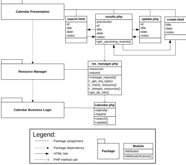
After making these simplifying assumptions, we designed the initial application. Figure 2 depicts the static perspective of the architecture for this system in the form of a module view.8 The element and relationship responsibilities in this view are provided in Table 5 and Table 6, respectively.
PHP was selected as the implementation language because of our experience and also because it is becoming a widely used language for web development [PHP 2010].
8
In practice, the redirection to the cloud would be handled by a load balancer. However, the Resource Manager com-ponent is the software equivalent of a load balancer and appropriate for this simple application and T-Check investi-gation.
Figure 2: Module View of the Initial System
Table 5: Element Responsibilities for the Module View of the Initial System
Associated Diagram: Figure 2; View: Module
Element Responsibilities
Calendar Presentation
Contains all modules that relate to the presentation of entries in the calendar— results.php, search.html, create.html, and update.php—which are served to the end user by an Apache9 web server (not shown here)
Allows the end user to issue a create, update, or search request to the system Relies on the Resource Manager package to allocate end user requests to the
appropriate set of resources
Resource Manager
Contains the res_manager.php module which is responsible for accepting a re-quest and submitting to a set of resources to be processed
Provides an interface for the Calendar Presentation package to submit requests and calls the Calendar Business Logic package to process these requests
9
The Apache web server is an open-source HTTP server maintained by the Apache Software Foundation (http://httpd.apache.org/) Calendar Presentation -id -title -date -notes search.html Resource Manager +manage_request() +_get_req_type() +_check_resource() +_release_resources() +get_db_info() -resources -request res_manager.php
Calendar Business Logic
+search() +update() -calendar -request calendar.php : Package assignment : Package dependency : HTML link
Legend:
: PHP method call Package +Methods/Actions() -Attributes Module +get_upcoming_events() -prevAction -id -title -date -notes results.php -title -date -notes create.html -id -title -date -notes update.phpTable 5: Element Responsibilities for the Module View of the Initial System (cont.)
Associated Diagram: Figure 2; View: Module
Element Responsibilities
Calendar Business Logic
Contains the calendar.php module which has access to all the entries in the calen-dar and allows these entries to be created, updated, or searched
Provides an interface for the Resource Manager package to submit these requests
results.php
Part of the Calendar Presentation package and is responsible for displaying the results of the end user's request
Contains links to the search.html, create.html, and update.php pages, which are used to issue requests
Does not accept any input from the end user
When an end user submits a request, that information is sent to this module which is then responsible for submitting the request and displaying the results. To do so it passes the request to the manage_request method of the resource_manager.php
module.
search.html
Part of the Calendar Presentation package and is responsible for accepting the appropriate input from the end user to search the calendar for a set of entries Allows the end user to specify the ID, title, date, and/or notes of the entries they are
looking for
Upon receipt of an end user's request, it passes the request to the results.php
module, which will display the results from the calendar search. Does not display any calendar information to the end user
create.html
Part of the Calendar Presentation package and is responsible for accepting the appropriate input from the end user to create a new entry in the calendar Allows the end user to specify the title, date, and/or notes of the entries to create Upon receipt of an end user's request, it will pass the request to the results.php
module, which will display the results from creating the entry. Does not display any calendar information to the end user
update.php
Part of the Calendar Presentation package and is responsible for accepting the appropriate input from the end user to update an entry in the calendar Receives the information about an entry from the results.php module and then
populates the text fields with this information to allow the end user to edit the title, date, and/or notes
Upon receipt of an end user's request, it passes the request to the results.php
module, which will display the results from updating the entry. Does not display any calendar information to the end user
res_manager.php
Part of the Resource Manager package and is responsible for accepting requests from the results.php module, identifying the type of request, identifying the current availability of the internal resources, and assigning the request to the appropriate set of resources (internal or cloud) to process the request
Forwards all requests to the appropriate method of the calendar.php module in the selected set of resources
calendar.php
Part of the Calendar Business Logic package and is responsible for servicing the various types of end user requests
Keeps track of all entries in the calendar and allows for them to be searched, created, or updated with the appropriate request
Receives requests from the res_manager.php module, processes them, and re-turns the results back to the res_manager.php module
Table 6: Relationship Responsibilities for the Module View of the Initial System
Associated Diagram: Figure 2; View: Module
Relationship Responsibilities
Indicates which modules are assigned to a given package
A package can contain an arbitrary number of modules, but a module may be as-signed to only one package.
Indicates the dependencies between the packages of the system
If package A is dependent on package B, then in order for package A to function properly, package B must be functioning properly.
In this system, this relationship is realized by PHP method calls between the mod-ules contained in the packages.
Indicates that an HTML link exists between the two modules
The direction of the relationship points to the destination module of the link. Indicates that a PHP method call is made between two given modules in the
sys-tem
The direction of the relationship points to the module that is being called.
3.2 Defining the System Architecture for Testing Hypothesis 1
With the architecture of the initial system as a starting point, we designed a solution to evaluate the criteria corresponding to the first hypothesis. This system focuses on managing the available re-sources, both internal and cloud rere-sources, transparently to the end user.
3.2.1 Dynamic View of the Solution for Testing Hypothesis 1
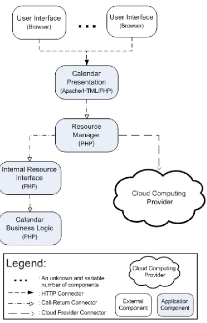
In this solution, the end users’ data needs to be stored in both the internal resources and in the cloud. The cloud will be utilized only for requests that exceed the capacity of the internal resources, when many end users simultaneously try to access the information in the calendar. Figure 3 shows the dy-namic perspective of this solution in the form of a component and connector diagram. The element and relationship responsibilities associated with this diagram are provided in Table 7 and Table 8, re-spectively.
Figure 3: Component and Connector View of the Solution for Testing Hypothesis 1
Table 7: Element Responsibilities for the Component and Connector View of the Solution for Testing Hy-pothesis 1
Associated Diagram: Figure 3; View: Dynamic
Element Responsibilities
User Interface
Represents the web browser employed by the end user
Renders any and all information provided by the Calendar Presentation component Allows the end user to enter information and passes it to the Calendar Presentation
component
Calendar Presentation
Combination of HTML and PHP that allows the end user to submit requests
Passes the requests to the Resource Manager component to be allocated to the appropriate resources for processing
Receives the resulting information from the Resource Manager component and formats it to be displayed to the end user
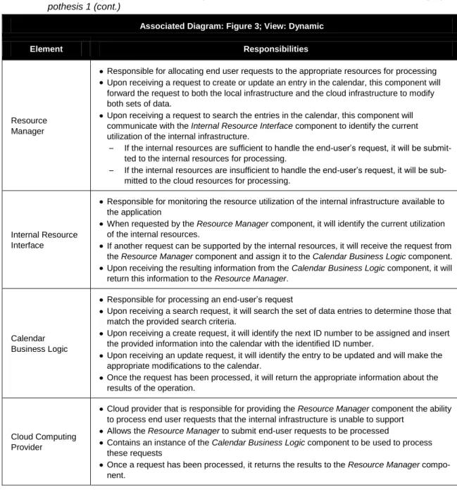
Table 7: Element Responsibilities for the Component and Connector View of the Solution for Testing Hy-pothesis 1 (cont.)
Associated Diagram: Figure 3; View: Dynamic
Element Responsibilities
Resource Manager
Responsible for allocating end user requests to the appropriate resources for processing Upon receiving a request to create or update an entry in the calendar, this component will
forward the request to both the local infrastructure and the cloud infrastructure to modify both sets of data.
Upon receiving a request to search the entries in the calendar, this component will communicate with the Internal Resource Interface component to identify the current utilization of the internal infrastructure.
– If the internal resources are sufficient to handle the end-user’s request, it will be submit-ted to the internal resources for processing.
– If the internal resources are insufficient to handle the end-user’s request, it will be sub-mitted to the cloud resources for processing.
Internal Resource Interface
Responsible for monitoring the resource utilization of the internal infrastructure available to the application
When requested by the Resource Manager component, it will identify the current utilization of the internal resources.
If another request can be supported by the internal resources, it will receive the request from
the Resource Manager component and assign it to the Calendar Business Logic component.
Upon receiving the resulting information from the Calendar Business Logic component, it will return this information to the Resource Manager.
Calendar Business Logic
Responsible for processing an end-user’s request
Upon receiving a search request, it will search the set of data entries to determine those that match the provided search criteria.
Upon receiving a create request, it will identify the next ID number to be assigned and insert the provided information into the calendar with the identified ID number.
Upon receiving an update request, it will identify the entry to be updated and will make the appropriate modifications to the calendar.
Once the request has been processed, it will return the appropriate information about the results of the operation.
Cloud Computing Provider
Cloud provider that is responsible for providing the Resource Manager component the ability to process end user requests that the internal infrastructure is unable to support
Allows the Resource Manager to submit end-user requests to be processed
Contains an instance of the Calendar Business Logic component to be used to process these requests
Once a request has been processed, it returns the results to the Resource Manager compo-nent.
Table 8: Relationship Responsibilities for the Component and Connector View of the Solution for Testing Hypothesis 1
Associated Diagram: Figure 3; View: Dynamic
Relationship Responsibilities
Represents an HTTP connection between two components of the system Utilizes TCP/IP to transmit information between the components
The component to which the connector is pointing is the component receiving the HTTP request
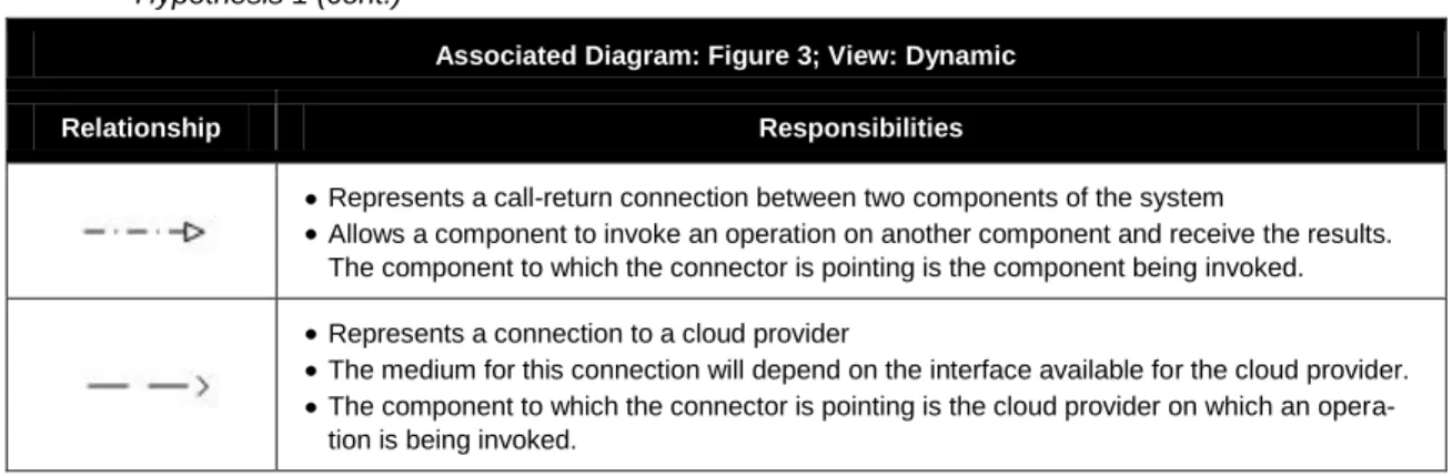
Table 8: Relationship Responsibilities for the Component and Connector View of the Solution for Testing Hypothesis 1 (cont.)
Associated Diagram: Figure 3; View: Dynamic
Relationship Responsibilities
Represents a call-return connection between two components of the system
Allows a component to invoke an operation on another component and receive the results. The component to which the connector is pointing is the component being invoked. Represents a connection to a cloud provider
The medium for this connection will depend on the interface available for the cloud provider. The component to which the connector is pointing is the cloud provider on which an
opera-tion is being invoked.
3.2.2 Deployment View of the Solution for Testing Hypothesis 1
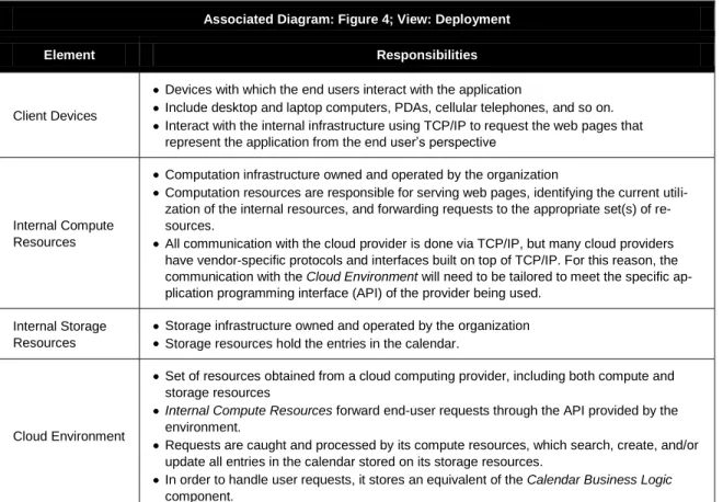
From the end-user’s perspective, the system should appear no different than if it were using only in-ternal resources. End users should have a single point of access for all requests and receive identical results from both the internal and cloud resources. All of the request and resource management will be done by a single Resource Manager component that will be deployed on the organization’s internal infrastructure. The deployment view of the system, as shown in Figure 4, identifies how the end user will interact with the system and how the components specified in Figure 3 will be deployed onto the available hardware. The element and relationship responsibilities associated with this diagram are provided in Table 9 and Table 10, respectively.
Table 9: Element Responsibilities for the Deployment View of the Solution for Testing Hypothesis 1
Associated Diagram: Figure 4; View: Deployment
Element Responsibilities
Client Devices
Devices with which the end users interact with the application
Include desktop and laptop computers, PDAs, cellular telephones, and so on. Interact with the internal infrastructure using TCP/IP to request the web pages that
represent the application from the end user’s perspective
Internal Compute Resources
Computation infrastructure owned and operated by the organization
Computation resources are responsible for serving web pages, identifying the current utili-zation of the internal resources, and forwarding requests to the appropriate set(s) of re-sources.
All communication with the cloud provider is done via TCP/IP, but many cloud providers have vendor-specific protocols and interfaces built on top of TCP/IP. For this reason, the communication with the Cloud Environment will need to be tailored to meet the specific ap-plication programming interface (API) of the provider being used.
Internal Storage Resources
Storage infrastructure owned and operated by the organization Storage resources hold the entries in the calendar.
Cloud Environment
Set of resources obtained from a cloud computing provider, including both compute and storage resources
Internal Compute Resources forward end-user requests through the API provided by the
environment.
Requests are caught and processed by its compute resources, which search, create, and/or update all entries in the calendar stored on its storage resources.
In order to handle user requests, it stores an equivalent of the Calendar Business Logic
component.
Table 10: Relationship Responsibilities for the Deployment View of the Solution for Testing Hypothesis 1
Associated Diagram: Figure 4; View: Deployment
Relationship Responsibilities
Represents the connection between the end users of the application and the Internal
Com-putation Resources of the organization
HTTP connection that is based on TCP/IP
Allows the end users to request web pages and supply the application with text information Represents the connection between the Internal Computation Resources and the Internal
Storage Resources
The entries of the calendar are stored in an SQL database.
Allows the computation resources to request a subset of the entries based on a provided set of criteria
Represents the connection between the Internal Computation Resources and the Cloud Environment
Dependent on the interface provided by the Cloud Environment
There is a variety of interfaces available, but at their most basic level, they all rely on TCP/IP.
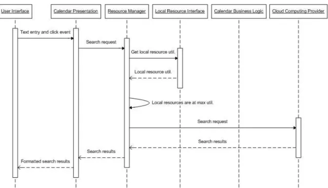
3.2.3 Defining the Resource Manager’s Behavior
This solution focuses on computation as the limiting resource. When a search request is received, the
Resource Manager checks to see whether the internal resources are capable of handling it; if they are, this component passes the request to the internal resources to be processed.10 If the internal resources are at their maximum capacity, the request is sent to the cloud resources to be processed. The se-quence diagrams for servicing a search request when the internal resources are or are not at their max-imum usage threshold are shown in Figure 5 and Figure 6, respectively.
Figure 5: Sequence Diagram for a Search Request when Internal Resources Are at Their Maximum Usage Threshold
10
In practice, the redirection to the cloud would most probably be handled by a load balancer or proxy. However, the
Resource Manager component is the software equivalent that is appropriate for this simple application and T-Check investigation.
Figure 6: Sequence Diagram for a Search Request when Internal Resources Are Not at Their Maximum Usage Threshold
When a request to create a new entry or to update an existing entry is received, the Resource Manager
sends the request to both the internal resources and the cloud resources to update both databases ap-propriately. This ensures consistency between the internal and cloud resources. The sequence diagram for servicing a create or an update request is provided in Figure 7.
3.3 Defining the System Architecture for Testing Hypothesis 2
The solution for evaluating hypothesis 2 builds upon the system for testing hypothesis 1. It focuses on the organization’s ability to monitor and continuously update the amount of cloud resources at its dis-posal. With this in mind, we added an administrative console to the system, which could acquire and release cloud resources as necessary.
3.3.1 Dynamic View of the Solution for Testing Hypothesis 2
In this solution, the system administrator is able to access and update the information about the cloud resources available to the system through an administrative console. Figure 8 shows the dynamic view of this solution in the form of a component and connector diagram. The element and relationship re-sponsibilities associated with this diagram are provided in Table 11 and Table 12, respectively.
Table 11: Element Responsibilities for the Component and Connector View of the Solution for Testing Hypothesis 2
NOTE: The rows marked in bold correspond to the changes with respect to the solution for testing hypothesis 1.
Associated Diagram: Figure 8; View: Dynamic
Element Responsibilities
User Interface
Represents the web browser employed by the end user
Renders any and all information provided by the Calendar Presentation component Allows the end user to enter information and passes it to the Calendar Presentation
component
Administrator Interface
Represents the web browser employed by the system administrator
Allows the system administrator to access information about cloud resources Allows the system administrator to update the cloud resources currently allocated to the system
Calendar Presentation
Combination of HTML and PHP that allows the end user to submit requests
Passes the requests to the Resource Manager component to be allocated to the appro-priate resources for processing
Receives the resulting information from the Resource Manager component and formats it to be displayed to the end user
Administrative Console
Combination of HTML and PHP that utilizes the API provided by the cloud provider to obtain information about cloud resources and update cloud resources currently allocated to the system
Receives the resulting information from the Cloud Computing Provider compo-nent and formats it to be displayed to the system administrator
Resource Manager
Responsible for allocating end user requests to the appropriate resources for processing Upon receiving a request to create or update an entry in the calendar, this component
will forward the request to both the local infrastructure and the cloud infrastructure to modify both sets of data.
Upon receiving a request to search the entries in the calendar, this component will communicate with the Internal Resource Interface component to identify the current utili-zation of the internal infrastructure.
– If the internal resources are sufficient to handle the end user’s request, it will be submitted to the internal resources for processing.
– If the internal resources are insufficient to handle the end user’s request, it will be submitted to the cloud resources for processing.
Internal Resource Interface
Responsible for monitoring the resource utilization of the internal infrastructure available to the application
When requested by the Resource Manager component, it will identify the current utiliza-tion of the internal resources.
If another request can be supported by the internal resources, it will receive the request from the Resource Manager component and assign it to the Calendar Business Logic
component.
Upon receiving the resulting information from the Calendar Business Logic component, it will return this information to the Resource Manager.
Table 11: Element Responsibilities for the Component and Connector View of the Solution for Testing Hypothesis 2 (cont.)
Associated Diagram: Figure 8; View: Dynamic
Element Responsibilities
Calendar Business Logic
Responsible for processing an end user’s request
Upon receiving a search request, it will search the set of data entries to determine those that match the provided search criteria.
Upon receiving a create request, it will identify the next ID number to be assigned and insert the provided information into the calendar with the identified ID number. Upon receiving an update request, it will identify the entry to be updated, and will make
the appropriate modifications to the calendar.
Once the request has been processed, it will return the appropriate information about the results of the operation.
Cloud Computing Provider
Cloud provider that is responsible for providing the Resource Manager component the ability to process user requests that the internal infrastructure is unable to support Allows the Resource Manager to submit user requests to be processed
Contains an instance of the Calendar Business Logic component to be used to process these requests
Once a request has been processed, it returns the results to the Resource Manager
component.
Also provides a resource management interface
Table 12: Relationship Responsibilities for the Component and Connector View of the Solution for Testing Hypothesis 2
Associated Diagram: Figure 8; View: Dynamic
Relationship Responsibilities
Represents an HTTP connection between two components of the system Utilizes TCP/IP to transmit information between the components
The component to which the connector is pointing is the component receiving the HTTP request.
Represents a call-return connection between two components of the system
Allows a component to invoke an operation on another component and receive the results The component to which the connector is pointing is the component being invoked. Represents a connection to a cloud provider
The medium for this connection will depend on the interface available for the cloud pro-vider.
The component to which the connector is pointing is the cloud provider on which an oper-ation is being invoked.
3.3.2 Deployment View of the Solution for Testing Hypothesis 2
In this solution, we have added a new user to the system, the system administrator. The system admin-istrator accesses the administrative console via HTTP requests. Figure 9 identifies how the system administrator will interact with the system and how the components specified in Figure 8 will be dep-loyed onto the available hardware. The element and relationship responsibilities catalogs associated with this diagram are provided in Table 13 and Table 14, respectively.
Figure 9: Deployment View for the Solution for Testing Hypothesis 2
Table 13: Element Responsibilities for the Deployment View of the Solution for Testing Hypothesis 2
NOTE: The rows marked in bold correspond to the changes with respect to the solution for testing hypothesis 1.
Associated Diagram: Figure 9; View: Deployment
Element Responsibilities
Administrator Device
Device with which the administrator interacts with the application May be a desktop or laptop computer, PDA, cellular telephone, and so on
Interacts with the Cloud Environment using the protocol specified by the cloud pro-vider to access and update information about the resources currently allocated to the system
Client Devices
Devices with which the end users interact with the application
Include desktop and laptop computers, PDAs, cellular telephones, and so on Interact with the internal infrastructure using TCP/IP to request the web pages that
Table 13: Element Responsibilities for the Deployment View of the Solution for Testing Hypothesis 2 (cont.)
Associated Diagram: Figure 9; View: Deployment
Element Responsibilities
Internal Compute Resources
Computation infrastructure owned and operated by the organization
Computation resources are responsible for serving web pages, identifying the current utili-zation of the internal resources, and forwarding requests to the appropriate set(s) of re-sources.
All communication with the Cloud Environment is done via TCP/IP, but many cloud envi-ronments have vendor-specific protocols and interfaces built on top of TCP/IP. For this rea-son, the communication with the Cloud Environment will need to be tailored to meet the specific API of the provider being used.
Internal Storage Resources
Storage infrastructure owned and operated by the organization Storage resources hold the entries in the calendar.
Cloud Environment
Set of resources obtained from a cloud computing provider, including both compute and storage resources
Internal Compute Resources forward end-user requests through the API provided by the
cloud provider.
Requests are caught and processed by its compute resources, which search, create, and/or update all entries in the calendar stored on its storage resources.
In order to handle end user requests, it stores an equivalent of the Calendar Business Logic
component.
Also provides a resource management interface
Table 14: Relationship Responsibilities for the Deployment View of the Solution for Testing Hypothesis 2
Associated Diagram: Figure 9; View: Deployment
Relationship Responsibilities
Represents the connection between the end users of the application and the Internal
Com-putation Resources of the organization
HTTP connection that is based on TCP/IP
Allows the end users to request web pages and supply the application with text information Represents the connection between the Internal Computation Resources and the Internal
Storage Resources
The entries of the calendar are stored in an SQL database.
Allows the computation resources to request a subset of the entries based on a provided set of criteria
Represents the connection used to access the Cloud Environment
Dependent on the interface provided by the cloud provider
There is a variety of interfaces available, but at their most basic level, they all rely on TCP/IP.
3.4 Defining the System Architecture for Testing Hypothesis 3
The solution for evaluating hypothesis 3 also builds on the system for testing hypothesis 1. It focuses on the ability of the organization to move an application from one cloud computing provider to anoth-er. This solution modifies an application that has been successfully deployed in a cloud provider to run in a new cloud provider.
3.4.1 Dynamic View of the Solution for Testing Hypothesis 3
For this solution, we incorporated a new cloud computing provider into the system. The assumptions are that the consequences of adding a new cloud provider will be isolated to the interface used by the Resource Manager for forwarding requests and that significant change to the other components will not be required. Figure 10 shows the dynamic view of this solution in the form of a component and connector diagram. The element and relationship responsibilities associated with this diagram are pro-vided in and Table 15 and Table 16, respectively.
Figure 10: Component and Connector View of the Solution for Testing Hypothesis 3
Table 15: Element Responsibilities for the Component and Connector View of the Solution for Testing Hypothesis 3
NOTE: The rows marked in bold correspond to the changes with respect to the solution for testing hypothesis 1.
Associated Diagram: Figure 10; View: Dynamic
Element Responsibilities
User Interface
Represents the Web browser employed by the end user
Renders any and all information provided by the Calendar Presentation component Allows the end user to enter information and passes it to the Calendar Presentation
Table 15: Element Responsibilities for the Component and Connector View of the Solution for Testing Hypothesis 3 (cont.)
Associated Diagram: Figure 10; View: Dynamic
Element Responsibilities
Calendar Presentation
Combination of HTML and PHP that allows the end user to submit requests
Passes the requests to the Resource Manager component to be allocated to the appro-priate resources for processing
Receives the resulting information from the Resource Manager component and formats it to be displayed to the end user
Resource Manager
Responsible for allocating end user requests to the appropriate resources for processing Upon receiving a request to create or update an entry in the calendar, this component
will forward the request to both the local infrastructure and the cloud infrastructure to modify both sets of data.
Upon receiving a request to search the entries in the calendar, this component will communicate with the Internal Resource Interface component to identify the current utili-zation of the internal infrastructure.
– If the internal resources are sufficient to handle the end user’s request, it will be submitted to the internal resources for processing.
– If the internal resources are insufficient to handle the end user’s request, it will be submitted to the cloud resources for processing.
Internal Resource Interface
Responsible for monitoring the resource utilization of the internal infrastructure available to the application
When requested by the Resource Manager component, it will identify the current utiliza-tion of the internal resources.
If another request can be supported by the internal resources, it will receive the request from the Resource Manager component and assign it to the Calendar Business Logic
component.
Upon receiving the resulting information from the Calendar Business Logic component, it will return this information to the Resource Manager.
Calendar Business Logic
Responsible for processing an end user’s request
Upon receiving a search request, it will search the set of data entries to determine those that match the provided search criteria.
Upon receiving a create request, it will identify the next ID number to be assigned and insert the provided information into the calendar with the identified ID number. Upon receiving an update request, it will identify the entry to be updated, and will make
the appropriate modifications to the calendar.
Once the request has been processed, it will return the appropriate information about the results of the operation.
Original Cloud Computing Provider
Cloud provider that is currently responsible for providing the ability to process user requests that the internal infrastructure is unable to support to the Resource
Manager component
Allows the Resource Manager to submit user requests to be processed Contains an instance of the Calendar Business Logic component to be used to process these requests
Once a request has been processed, it returns the results to the Resource Manag-er component.
New Cloud
Computing Provider
Cloud provider that is being transitioned to, that will be responsible for providing the Resource Manager component the ability to process user requests that the in-ternal infrastructure is unable to support
Will allow the Resource Manager to submit user requests to be processed Will contain an instance of the Calendar Business Logic component to be used to process these requests
Once a request has been processed, it will return the results to the Resource
Table 16: Relationship Responsibilities for the Component and Connector View of the Solution for Testing Hypothesis 3
NOTE: The rows marked in bold correspond to the changes with respect to the solution for testing hypothesis 1.
Associated Diagram: Figure 10; View: Dynamic
Relationship Responsibilities
Represents an HTTP connection between two components of the system Utilizes TCP/IP to transmit information between the components
The component to which the connector is pointing is the component receiving the HTTP request.
Represents a call-return connection between two components of the system Allows a component to invoke an operation on another component and receive the
re-sults
The component to which the connector is pointing is the component being invoked.
Represents a connection to the current cloud provider
The medium for this connection will depend on the interface available for the cur-rent cloud provider.
The component to which the connector is pointing is the cloud provider on which an operation is being invoked.
Represents a connection to the new cloud provider
The medium for this connection will depend on the interface available for the new cloud provider.
The component to which the connector is pointing is the cloud provider on which an operation will be being invoked.
3.4.2 Deployment View of the Solution for Testing Hypothesis 3
In this solution, we are replacing the cloud provider available to the internal resources with a new cloud provider. The assumption is that this modification to the system will be completely transparent to the end users of the system. The only changes required should be in the interface used to communi-cate with the cloud resources. Figure 11 shows how the new cloud provider will be integrated into the system and how the components specified in Figure 10 will be deployed onto the available hardware. The element and relationship responsibilities associated with this diagram are provided in Table 17 and Table 18, respectively.