CLIP
CLIP
CLIP
CLIP MCW
MCW
MCW //// CLIP T MCW
MCW
CLIP T MCW
CLIP T MCW
CLIP T MCW
Wireless Curtain-Type PowerCode Infrared Detector
Installation Instructions
1. INTRODUCTION
1. INTRODUCTION
1. INTRODUCTION
1. INTRODUCTION
The CLIP MCW is the smallest and most elegant wireless curtain-pattern PIR detector for indoor use and designed for easy installation. Its function is based on new and sophisticated, patented FM data acquisition and digital signal processing.
Modern technology is used to include 3 different detectors in a single case, each programmable for optimized performance at the specific mounting location. This results in better catch performance and virtually no false alarms.
The superiority in performance of this detector is achieved by applying an improved version of the patented True Motion Recognition™ (TMR) algorithm. This advanced motion analysis method allows the CLIP MCW to distinguish between the true motion of the human body and any other disturbances that cause false alarms.
After detection, the detector disarms itself to save battery power. It rearms (reverts to the ready state) if there is no subsequent detection throughout the following 2-minute period.
The CLIP MCW includes the following features:
• Very low current consumption
• Microprocessor-controlled temperature compensation • Sealed chamber protects the optical system
• Front cover tamper switch • Back tamper switch (CLIP T MCW) • White light protection
• Elegantly styled, sturdy case
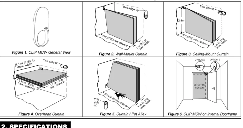
Detailed coverage patterns and mounting alternatives are illustrated in Figures 2 through 6.
Figure 1. CLIP MCW General View Figure2. Wall-Mount Curtain
2.4m
Figure 3. Ceiling-Mount Curtain
Figure 4. Overhead Curtain
This side up
Figure 5. Curtain / Pet Alley
OPTION A OPTION B
DETECTION CURTAIN
Figure 6. CLIP MCW on Internal Doorframe
2. SPECIFICATIONS
2. SPECIFICATIONS
2. SPECIFICATIONS
2. SPECIFICATIONS
OPTICAL
Detector Type: Dual-element low noise pyroelectric sensor. Number of Curtain Beams: 2
Mounting Positions: See Figures 2 through 6.
Range Settings: Long (6 m), Medium (4 m) and Short (1.2 - 2m) (Jumper-selected).
ELECTRICAL
Internal Battery: 3V Lithium battery, type CR123A. For UL installations, use Panasonic or Sanyo only.
Nominal Battery Capacity: 1450 mA/h.
Battery Life (with LED on): 3 years (for typical use).
Battery Power Test: Performed immediately upon battery insertion and periodically every several hours.
Microprocessor: 8-bit, low power CMOS. FUNCTIONAL
Visual Indications:
LED Lights for about 3 seconds upon transmission of alarm & tamper messages and upon motion detection in the walk test mode.
LED Flashes during the power-up stabilization period (approx. 2 min), or after restoring the cover (by pressing the tamper switch). LED Does not light upon transmission of supervision messages. Alarm Period: Approx. 3 seconds.
Rearm Timer: Rearms the detector 2 minutes after the last alarm.
WIRELESS
Frequency (MHz): 315 (U.S. version), 433.92, 868.95, 869.2625 or other frequency according to local requirements.
Transmission Sequence: 3 data bursts at variable intervals within 3 seconds.
Encoding: 24-bit ID, over 16 million possible combinations. Total Message Length: 36 bits.
Tamper Alert: Reported when a tamper event occurs and in any subsequent message, until the tamper switch is restored.
Supervision Message: Signaling at 60-minute intervals (U.S. version), 15 minute intervals (UK version), or according to the local standards.
MOUNTING
Height: 1.8 - 2.4 m (6 - 8 ft).
Installation Options: See Figures 9 through 13. ENVIRONMENTAL
Operating Temperature: -10°C to 50°C (14°F to 122°F). Storage Temperature: -20°C to 60°C (-4°F to 140°F). RFI Protection: > 20 V/m to 1000 MHz.
Compliance with standards:
Europe: EN 300220, EN 301489, EN 60950, EN 50131-2-2 Grade 2 Class II
USA: @ 315 Mhz complies with CFR 47 part 15 (FCC) Canada: RSS210
2
DE3594 CLIP MCW / CLIP T MCW Installation Instructions
PHYSICALDimensions (H x W x D): 105 x 35 x 30 mm (4-1/8 x 1-3/8 x 1-3/16 in.).
Weight (with battery): 60 g (2.1 oz).
Color: White. PATENTS
U.S. Patent 5,693,943 (other patents pending)
3. INSTALLATION
3. INSTALLATION
3. INSTALLATION
3. INSTALLATION
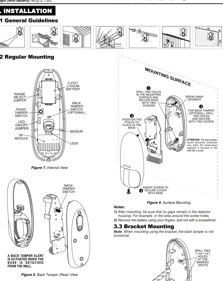
3.1 General Guidelines
3.2 Regular Mounting
3 VOLT LITHIUM BATTERY BACK TAMPER SWITCH (OPTIONAL) SENSOR LEDS RF MODULE FRONT TAMPER SWITCH RANGE SELECT JUMPER LED ON/OFF JUMPERFigure 7. Internal View
BACK TAMPER SWITCH
A BACK TAMPER ALERT IS ACTIVATED WHEN THE B A S E I S D E TA C H E D FROM THE WALL
Figure 8. Back Tamper (Rear) View
BREAK-AWAY SEGMENT
ATTENTION: The back tamper switch becomes functional only when the break-away segment is secured to the wall with a screw.
INSERT SCREW TO SECURE COVER WITH BASE 4 3 POSITION THE PCB IN ITS PLACE IN THE BASE 1 DRILL TWO HOLES IN THE MOUNTING SURFACE AND SECURE BASE WITH TWO
SCREWS 2
FOR BACK TAMPER (OPTIONAL), DRILL
TWO HOLES AND SECURE WITH TWO SCREW
Figure 9. Surface Mounting
Notes:
1) After mounting, be sure that no gaps remain in the detector housing. For example, in the area around the screw holes. 2) Remove the battery using your fingers, and not with a screwdriver.
3.3 Bracket Mounting
Note: When mounting using the bracket, the back tamper is not functional. DRILL TWO 7 mm (1/4“) HOLES AT THE MARKED SPOTS
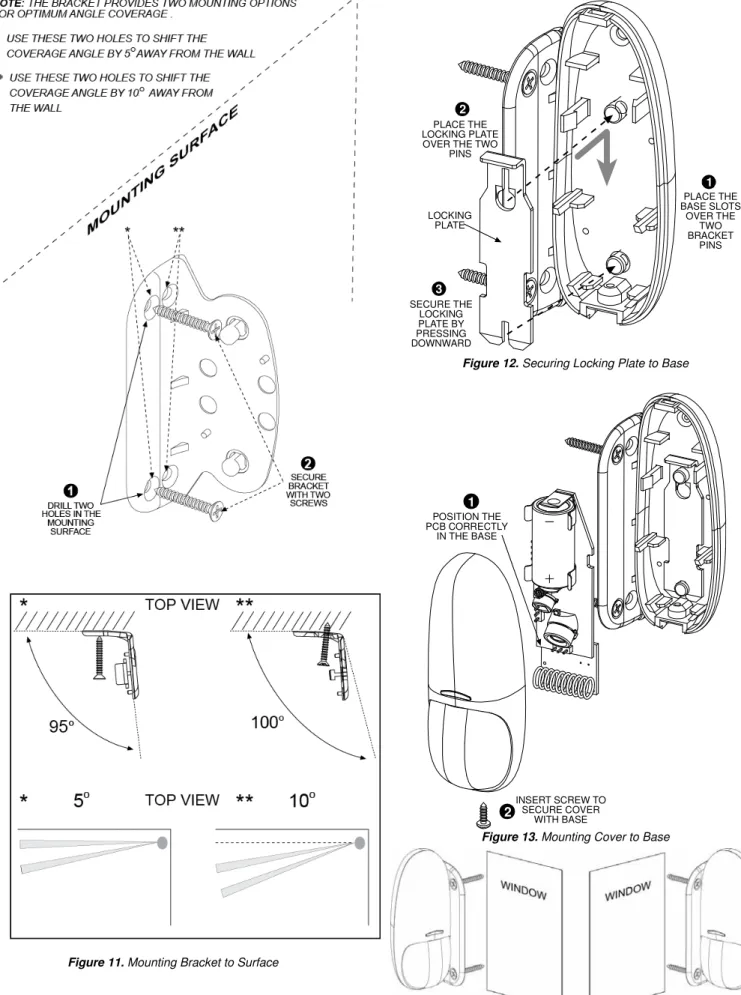
Figure 11. Mounting Bracket to Surface
PLACE THE LOCKING PLATE OVER THE TWO
PINS 2 SECURE THE LOCKING PLATE BY PRESSING DOWNWARD 3 LOCKING PLATE PLACE THE BASE SLOTS OVER THE TWO BRACKET PINS 1
Figure 12. Securing Locking Plate to Base
POSITION THE PCB CORRECTLY IN THE BASE
1
INSERT SCREW TO SECURE COVER WITH BASE2
Figure 13. Mounting Cover to Base
Note: The CLIP MCW can be mounted on either side of a window.
Figure 14. Mounting on Both Sides of a Window
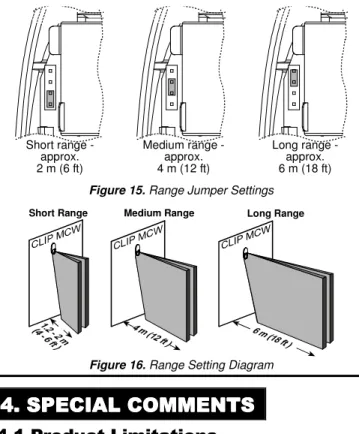
3.4 Setting the Coverage Range
A 4-pin jumper is used to select 3 ranges, according to the type of installation, for the curtain beams (see Figures 7 and 15).
4
DE3594 CLIP MCW / CLIP T MCW Installation Instructions
Short range -approx. 2 m (6 ft) Medium range -approx. 4 m (12 ft) Long range -approx. 6 m (18 ft)Figure 15. Range Jumper Settings
Short Range Medium Range Long Range
Figure 16. Range Setting Diagram
The purpose of the range setting is to ensure optimal signal processing and high immunity against false alarms.
Mount the range jumper in the desired position and make sure that the protected area is within the selected coverage range (see figure 16). Carry out a walk test (refer to Para. 3.5) to verify proper performance.
3.5 Walk Testing
A. Mount the cover and tighten the screw. Wait for the detector to stabilize (the LED stops flashing approx. two minutes after the cover is closed).
B. Walk slowly across the far end of the curtain pattern (in opposite directions). The LED indicator lights for approx. 3 seconds whenever you enter or exit a curtain beam.
Important: Perform walk test at least once a week to assure proper function of the detector.
Note: After closing the cover the detector enters a 15 minute walk-test mode. In this mode the LED will flash each time a detection occurs, regardless of LED jumper settings, and the detector will transmit on the occurrence of each detection event.
4. SPECIAL COMMENTS
4. SPECIAL COMMENTS
4. SPECIAL COMMENTS
4. SPECIAL COMMENTS
4.1 Product Limitations
Visonic Ltd. wireless systems are very reliable and are tested to high standards. However, due to their low transmitting power and limited range (required by FCC and other regulatory authorities), there are some limitations to be considered:
A. Receivers may be blocked by radio signals on or near their operating frequencies, regardless of the code selected.
B. A receiver can only respond to one signal at a time.
C. Wireless equipment should be tested regularly to determine whether there are sources of interference and to protect against faults.
D. Even the most sophisticated detectors can sometimes be defeated or may fail to warn due to: DC power failure / improper connection, malicious masking of the lens, tampering with the optical system, decreased sensitivity in ambient temperatures near that of the human body and unexpected failure of a component part.
The above list includes the most common reasons for failure to detect intrusion, but is by no means comprehensive. It is therefore recommended that the detector and the entire alarm system be checked weekly, to ensure proper performance.
E. An alarm system should not be regarded as a substitute for insurance. Home and property owners or renters should be prudent enough to continue insuring their lives and property, even though they are protected by an alarm system.
4.2 Compliance with Standards
The 315 MHz version of this device complies with Part 15 of the FCC Rules. Operation is subject to the following two conditions: (1) This device may not cause harmful interference, and (2) This device must accept any interference received, including interference that may cause undesired operation.
WARNING! Changes or modifications to this unit not expressly approved by the party responsible for compliance could void the user's authority to operate the equipment.
This device complies with Industry Canada licence-exempt RSS standard(s). Operation is subject to the following two conditions: (1) this device may not cause harmful interference, and (2) this device must accept any interference, including interference that may cause undesired operation of the device.
Le présent appareil est conforme aux CNR d'Industrie Canada applicables aux appareils radio exempts de licence. L'exploitation est autorisée aux deux conditions suivantes : (1) l'appareil ne doit pas produire de brouillage, et (2) l'utilisateur de l'appareil doit accepter tout brouillage radioélectrique subi, même si le brouillage est susceptible d'en compromettre le fonctionnement.
The digital circuit of this device has been tested and found to comply with the limits for a Class B digital device, pursuant to Part 15 of the FCC Rules. These limits are designed to provide reasonable protection against harmful interference in residential installations. This equipment generates uses and can radiate radio frequency energy and, if not installed and used in accordance with the instructions, may cause harmful interference to radio and television reception. However, there is no guarantee that interference will not occur in a particular installation. If this device does cause such interference, which can be verified by turning the device off and on, the user is encouraged to eliminate the interference by one or more of the following measures:
– Re-orient or re-locate the receiving antenna.
– Increase the distance between the device and the receiver. – Connect the device to an outlet on a circuit different from the one
which supplies power to the receiver.
– Consult the dealer or an experienced radio/TV technician.
4.3 Frequency Allocations for Wireless
Devices in European (EU) Countries
• 315 MHz is not allowed in any EU member state.
• 433.92 MHz has no restriction in any EU member state.
• 868.95MHz(wide band) is allowed in all EU member states. • 869.2625MHz(narrow band) is not restricted in any EU member state. The technical documentation as required by the European Conformity Assessment procedure is kept at:
UNIT 6 MADINGLEY COURT CHIPPENHAM DRIVE KINGSTON MILTON KEYNES MK10 0BZ. Telephone number: 0870 7300800, Fax number: 0870 7300801 W.E.E.E. Product Recycling Declaration
For information regarding the recycling of this product you must contact the company from which you orignially purchased it. If you are discarding this product and not returning it for repair then you must ensure that it is returned as identified by your supplier. This product is not to be thrown away with everyday waste.
Directive 2002/96/EC Waste Electrical and Electronic Equipment.
VISONIC LTD. (ISRAEL): P.O.B 22020 TEL-AVIV 61220 ISRAEL. PHONE: (972-3) 645-6789, FAX: (972-3) 645-6788
VISONIC INC. (U.S.A.): 65 WEST DUDLEY TOWN ROAD, BLOOMFIELD CT. 06002-1376. PHONE: (860) 243-0833, (800) 223-0020. FAX: (860) 242-8094
VISONIC LTD. (UK): UNIT 6 MADINGLEY COURT CHIPPENHAM DRIVE KINGSTON MILTON KEYNES MK10 0BZ. TEL: (0845) 0755800 FAX: (0845) 0755801. PRODUCT SUPPORT: (0845) 0755802
VISONIC GmbH (D-A-CH): KIRCHFELDSTR. 118, D-40215 DÜSSELDORF, TEL.: +49 (0)211 600696-0, FAX: +49 (0)211 600696-19
VISONIC IBERICA: ISLA DE PALMA, 32 NAVE 7, POLÍGONO INDUSTRIAL NORTE, 28700 SAN SEBASTIÁN DE LOS REYES, (MADRID), ESPAÑA. TEL (34) 91659-3120, FAX (34) 91663-8468. www.visonic-iberica.es
INTERNET: www.visonic.com
CLIP MCW / CLIP T MCW
INSTALLATION INSTRUCTIONS ADDENDUM
Please refer to the following changes in the CLIP MCW / CLIP T MCW installation instructions, Cat. # DE3594-, revision 3 only.
2. SPECIFICATIONS
Compliance with standards:Europe: EN 300220, EN 301489, EN 60950, EN 50131-2-2 Grade 2 Class II USA: @ 315 MHz complies with CFR 47 part 15 (FCC)
Canada: RSS210
3. INSTALLATION
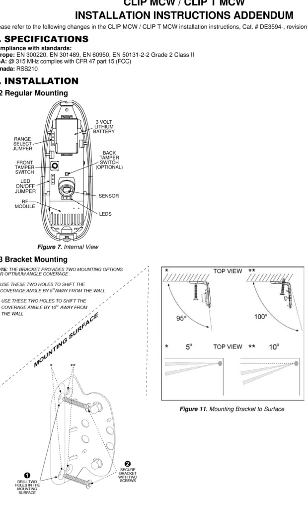
3.2 Regular Mounting
3 VOLT LITHIUM BATTERY BACK TAMPER SWITCH (OPTIONAL) SENSOR LEDS RF MODULE FRONT TAMPER SWITCH RANGE SELECT JUMPER LED ON/OFF JUMPERFigure 7. Internal View
3.3 Bracket Mounting
2
D-303643
3.3 Bracket Mounting (Continued)
Note: The CLIP MCW can be mounted on either side of a window.
Figure 14. Mounting on Both Sides of a Window
3.4 Setting the Coverage Range
A 4-pin jumper is used to select 3 ranges, according to the type of installation, for the curtain beams (see Figures 7 and 15).
Short range -approx. 2 m (6 ft) Medium range -approx. 4 m (12 ft) Long range -approx. 6 m (18 ft)
Figure 15. Range Jumper Settings
4. SPECIAL COMMENTS
4.2 Compliance with Standards
This device complies with Industry Canada licence-exempt RSS standard(s). Operation is subject to the following two conditions: (1) this device may not cause harmful interference, and (2) this device must accept any interference, including interference that may cause undesired operation of the device.
Le présent appareil est conforme aux CNR d'Industrie Canada applicables aux appareils radio exempts de licence. L'exploitation est autorisée aux deux conditions suivantes : (1) l'appareil ne doit pas produire de brouillage, et (2) l'utilisateur de l'appareil doit accepter tout brouillage radioélectrique subi, même si le brouillage est susceptible d'en compromettre le fonctionnement.
The technical documentation as required by the European Conformity Assessment procedure is kept at:
UNIT 6 MADINGLEY COURT CHIPPENHAM DRIVE KINGSTON MILTON KEYNES MK10 0BZ. Telephone number: 0870 7300800, Fax number: 0870 7300801 W.E.E.E. Product Recycling Declaration
For information regarding the recycling of this product you must contact the company from which you orignially purchased it. If you are discarding this product and not returning it for repair then you must ensure that it is returned as identified by your supplier. This product is not to be thrown away with everyday waste.
Directive 2002/96/EC Waste Electrical and Electronic Equipment.
VISONIC LTD. (ISRAEL): P.O.B 22020 TEL-AVIV 61220 ISRAEL. PHONE: (972-3) 645-6789, FAX: (972-3) 645-6788
VISONIC INC. (U.S.A.): 65 WEST DUDLEY TOWN ROAD, BLOOMFIELD CT. 06002-1376. PHONE: (860) 243-0833, (800) 223-0020. FAX: (860) 242-8094
VISONIC LTD. (UK): UNIT 6 MADINGLEY COURT CHIPPENHAM DRIVE KINGSTON MILTON KEYNES MK10 0BZ. TEL: (0845) 0755800 FAX: (0845) 0755801. PRODUCT SUPPORT: (0845) 0755802
VISONIC GmbH (D-A-CH): KIRCHFELDSTR. 118, D-40215 DÜSSELDORF, TEL.: +49 (0)211 600696-0, FAX: +49 (0)211 600696-19
VISONIC IBERICA: ISLA DE PALMA, 32 NAVE 7, POLÍGONO INDUSTRIAL NORTE, 28700 SAN SEBASTIÁN DE LOS REYES, (MADRID), ESPAÑA. TEL (34) 91659-3120, FAX (34) 91663-8468. www.visonic-iberica.es
INTERNET: www.visonic.com