Fang, Mai
For additional information about this publication click this link. http://qmro.qmul.ac.uk/xmlui/handle/123456789/11748
Information about this research object was correct at the time of download; we occasionally make corrections to records, please therefore check the published record when citing. For more information contact [email protected]
1
bio-based poly(lactic acid) composites
SUBMITTED IN PARTIAL FULFILLMENT OF THE REQUIREMENTS
OF THE DEGREE OF DOCTOR OF PHILOSOPHY
June 2015
Fang Mai
School of Engineering and Materials Science
Queen Mary University of London
2
I declare that the work performed is entirely by myself during the course of my Ph.D studies at the Queen Mary University of London and has not been submitted for a degree at this or any other University.
3
Researchers are like Sherlock Holmes. We are searching for hidden clues and then reasoning them. This dissertation is not only a personal accomplishment; it is also a product of many people. It took more than determination and hard work for the completion of this thesis.
I would like to acknowledge first the China Scholarship Council (CSC) for the financial support, as well as offering me the opportunity for further study and this great international experience.
Especially, I give my supervisors Dr. Ton Peijs and Dr. Emiliano Bilotti all my gratefulness for giving me the opportunity to work on the HIGHBIOPOL project, and for all the support and guidance during my PhD. Ton‟s sense of humour, easily understood explanations and open mind allowed me to grow. Emiliano‟s patience and kindness guided me through the process.
I gratefully acknowledge the support of Mr. Kaloyan Palatov for the teamwork and early development of the project during the first year. I would like to thank Dr. Wei Tu for his constant help and his invaluable inputs through the project. I also want to thank the technical staff Mr. Vince Ford for designing and manufacturing some of the experimental equipments.
Many thanks to my collaborator, Dr. Alexandre Clerbaux, Mr. Fang-Yue Chan, Mr. Michael Mainil, Dr. Michael Claes, and Mr. Julien Amadou in Nanocyl S.A. (Belgium); Dr. Youssef Habibi, Dr. Jean-Marie Raquez, and Dr. Philippe Dubois in University of Mons (Belgium).
4
A huge thank to my soul mate and husband Dong Dong for his love and understanding during my good and bad times. He always stands by my side, and there is no word to convey how much I love him.
I would also like to thank my friends and family for their continual support and encouragement during my stressful stages.
I looked back these years and want to say, doing a PhD was tough, but great, and I would totally do it again.
5
Following the eco-design concepts, this thesis investigated the manufacturing and properties of multifunctional bioplastic poly(lactic acid) (PLA) based composites. The main advantages of using bio-based polymer are to create performance products from sustainable resources, competing with fossil hydrocarbon sourced polymers, at the same time leaving open the possibility of composting as an alternative end-of-life option in addition to recycling.
In Part I, self-reinforced PLA (SR-PLA) composites were produced based on oriented PLA tapes and a thin layer of PLA matrix, which were combined using a film-stacking technique into a „brick-and-mortar‟ laminated structure. The optimization of the uniaxial drawing and structure of these tapes, together with a study of the interfacial, tensile, impact and thermal properties of the obtained SR-PLA composites were investigated. In order to be successful in more demanding engineering applications the important issue regarding biodegradation during the PLA-based product‟s lifetime needs to be addressed. Therefore, monitoring of degradation levels during usage is of a vital interest. This is the subject of study of the 2nd part of the thesis.
In Part II the aim is to develop multifunctional engineering bioplastics with improved performances (mechanical and electrical) and added functionalities (sensing properties). An in-situ degradation monitoring system for biodegradable polymers was successfully developed through the incorporation of carbon nanotubes (CNTs) in PLA. Changes in electrical resistivity of the PLA/CNT nanocomposites were successfully correlated with degradation levels of this bioplastic. PLA/CNT nanocomposites demonstrated excellent degradation sensing abilities at CNT concentrations around the percolation threshold,
6
make them ideal reinforcing fillers for polymeric fibres. Therefore, the influence of CNT content and solid-state drawing on microstructure and the resulting mechanical and electrical properties of these nanocomposites were investigated.
7 Acknowledgements ... 3 Abstract ... 5 Table of Contents ... 7 List of Tables ... 12 List of Figures ... 14 Chapter 1.Introduction ... 20
1.1 End of life options for composite waste: Recycle, reuse or dispose? ... 20
1.2 Objectives ... 23
1.3 Scope of the thesis ... 27
1.4 References ... 28
Part I. Bio-based self-reinforced polymer composites ... 30
Chapter 2. Literature review ... 31
2.1 Poly(lactic acid) (PLA): A sustainable bioplastic ... 31
2.2 Natural fibre reinforced PLA composites... 35
2.3 Self-reinforced polymer composites... 42
2.3.1 Self-reinforced polymer composites ... 42
2.3.2 Self-reinforced poly(lactic acid) composites ... 47
2.3.2.1 PLA fibre ... 47
2.3.2.2 Self-reinforced PLA composites ... 51
8
3.1 Introduction ... 61
3.2 Experimental ... 62
3.2.1. Materials ... 62
3.2.2. Manufacture of PLA tapes ... 62
3.2.3. Characterization ... 63
3.3 Results and discussion ... 66
3.3.1 The influence of drawing on mechanical properties of PLA tape ... 66
3.3.2 The influence of drawing on thermal properties of PLA tapes ... 71
3.3.3 Structure development in PLA tapes during solid-state drawing ... 75
3.4. Conclusions ... 83
3.5 References ... 83
Chapter 4. Manufacturing and properties of SR-PLA composites ... 85
4.1 Introduction ... 85
4.2 Experimental ... 86
4.2.1 Materials ... 86
4.2.2 Manufacture of SR-PLA composites ... 87
4.2.3 Corona treatment of PLA tapes and matrix ... 89
4.2.4 Characterization ... 90
4.3 Results and discussion ... 92
4.3.1 Tailoring the interfacial properties of SR-PLA composites ... 92
9
4.3.5 Prototypes ... 103
4.4 Conclusions ... 104
4.5 References ... 105
Part II. Multifunctional poly(lactic acid)/carbon nanotube nanocomposites ... 107
Chapter 5.Literature review ... 108
5.1 Carbon nanotubes ... 109
5.1.1 Atomic structure and morphology of carbon nanotube ... 109
5.1.2 Properties of carbon nanotubes ... 110
5.2 Mechanical properties of polymer/CNT composites ... 114
5.2.1 Nanoplatelets vs nanofibres ... 114
5.2.2 Mechanical properties of polymer/CNT composites ... 118
5.3 Electrical conductivity of polymer/CNT composites ... 120
5.4 Carbon nanotube-based composite sensors ... 123
5.5 References ... 126
Chapter 6. Conductive poly(lactic acid) tape reinforced with carbon nanotubes130 6.1 Introduction ... 130
6.2 Experimental ... 132
6.2.1 Materials and sample preparation ... 132
10 6.3.2 Rheological behaviour ... 137 6.3.3 Mechanical properties ... 141 6.3.4 Micromechanical analysis ... 144 6.3.5 Morphology change ... 146 6.3.6 Electrical properties ... 150 6.4 Conclusions ... 152 6.5 References ... 153
Chapter 7. Poly(lactic acid)/carbon nanotube nanocomposites with integrated degradation sensing ... 156 7.1 Introduction ... 156 7.2 Experimental ... 157 7.2.1 Materials ... 157 7.2.2 Sample preparation ... 157 7.2.3 Hydrolytic degradation ... 158 7.2.4 Characterization ... 159
7.3 Results and discussion ... 160
7.3.1 Hydrolytic degradation and morphological changes ... 160
7.3.2 Degradation sensing ... 167
7.4 Conclusions ... 173
11
8.3.1 Technology assessment ... 177
8.3.2 Feedback from interviews ... 181
8.2 Summary ... 185
8.3 Future work ... 188
12
Table 2.1 Comparison of the mechanical properties of PLA-based green composites. .. 37
Table 2.2 Properties of oriented PLA fibre/tape. ... 48
Table 2.3 Mechanical properties of SR-PLA composite as reported in literature... 52
Table 3.1 Default extrusion parameters. ... 63
Table 3.2 Solid-state drawing parameters (to give different DR) ... 63
Table 3.3 Tensile properties of various PLA tapes. ... 70
Table 3.4 Herman‟s orientation factors of various PLA tapes obtained by WAXS. ... 78
Table 4.1 Energy absorption mechanism of SR-PLA composites. ... 100
Table 4.2 The heat deflection temperature (HDT) and corresponding crystallinity (Xc) of the PLA and SR-PLA composites. ... 102
Table 5.1 Summary and comparison of reinforcement of SWNT and MWNT composites fabricated by various methods, where Y is the composite Young‟s modulus, σ is the composite strength, and Vf is the nanotube volume fraction [33]. ... 120
Table 6.1 Comparison of PLA/CNT nanocomposites fabricated by various methods and present work, where Ec is the composite Young‟s modulus, σ is the composite strength, and Vf is the nanotube volume fraction. ... 143
Table 6.2 Summary of reinforcement of MWNT in nanocomposites drawn at various draw ratios, where Ec is the composite Young‟s modulus, Vf is the nanotube volume fraction, σ is the composite strength, and lNT/DNTis the aspect ratio of MWNT. ... 146
Table 6.3 The glass transition temperature (Tg), melting temperature (Tm), and crystallinity (Xc) of neat PLA and PLA/MWNT composites. ... 147
14
Figure 1.1 The waste hierarchy and examples on each level. ... 22
Figure 1.2 Life cycle of SR-PLA composites. ... 24
Figure 1.3 Schematic of the hot compaction process. ... 25
Figure 2.1 Two stereoisomers of lactic acid. ... 32
Figure 2.2 Polymerization routes to PLA [3]. ... 33
Figure 2.3 Examples of molecular configurations of PLA obtained through combining the two lactic acid isomers in varying proportions [3]. ... 34
Figure 2.4 Density specific mechanical properties [14]... 36
Figure 2.5 Consolidation of a SRPs from homogenous fibres by a hot compaction technology [41]. ... 43
Figure 2.6 Etched micrographs from unidirectional melt-spun CERTRAN PE fibres. (a) SEM picture of a transverse section of compacted fibres. (b) TEM picture of an interstitial lamellar region and its junction with adjacent fibres. ... 44
Figure 2.7 Co-extrusion technology is used for the development of high-performance PP tapes. These tapes consist of a highly oriented core (B) and a thin polymer skin (A) to weld the tapes together in a subsequent consolidation process. ... 45
Figure 2.8 Optical micrograph of a cross-section of a co-extruded PP woven tape-based SRP [51]. ... 46
Figure 2.9 Supra-morphological model for two-step, melt-spun PLA [74]. ... 50
Figure 3.1 Schematic of extrusion and solid-state drawing pilot-production line. ... 62
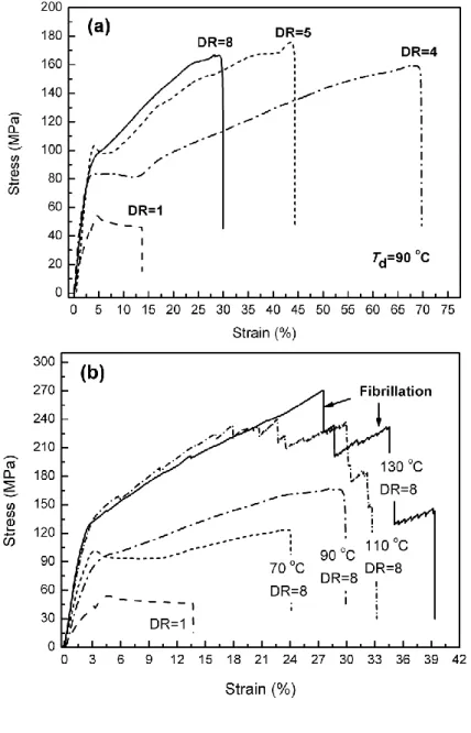
Figure 3.2 Stress-strain curves of PLA films and tapes subjected to (a) various draw ratios (Td=90 oC), and (b) different drawing temperatures (DR=8). ... 67
15
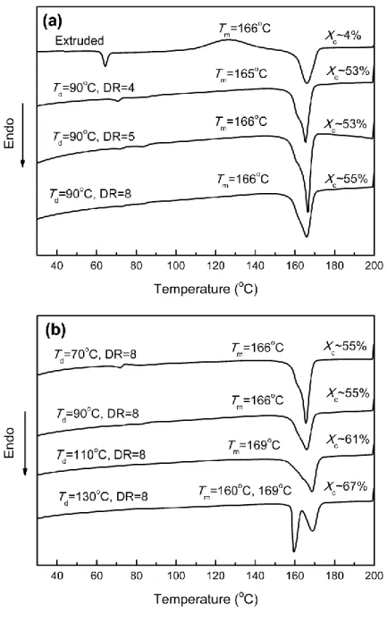
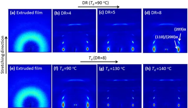
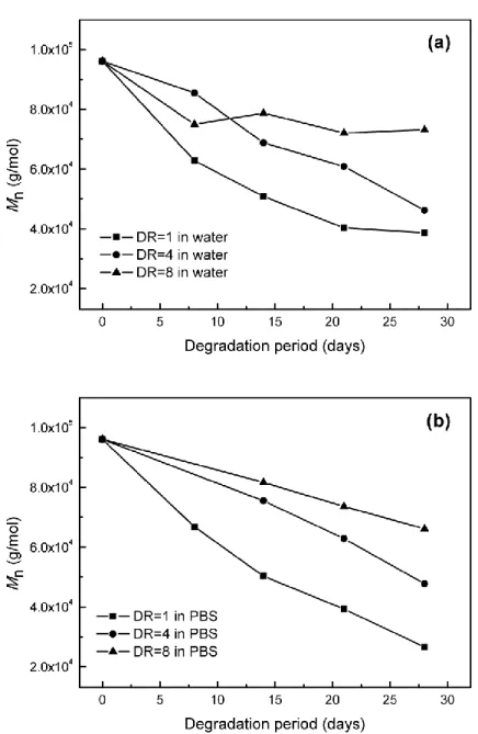
Figure 3.4 DSC thermograms of (a) samples drawn at 90 oC with various draw ratios, and (b) samples drawn at different temperatures with draw ratio of 8. ... 72 Figure 3.5 (a) Storage modulus and (b) loss factor against temperature for a range of PLA tapes with increasing draw ratio; (c) Storage modulus vs. draw ratio for a range of PLA tapes with increasing test temperature ... 74 Figure 3.6 Infrared spectra in the 800-1000 cm-1 region for a DR series prepared at different drawing temperature. ... 77 Figure 3.7 2D WAXS patterns of (a, e) as-extruded films, tapes drawn at 90 oC with DR of (b) 4, (c) 5 and (d, f) 8, and PLA tapes drawn at (g) 130 °C (DR=8) and (h) 140 °C (DR=8).The patterns were recorded with the incident beam perpendicular to the tapes. ... 78 Figure 3.8 Optical appearance of PLA tapes. From left to right; as-extruded film, tapes drawn at 90 oC to DR=4, 5 and 8. There is a clear transition from fully transparent to an opaque tape structure at DR > 5. ... 79 Figure 3.9 SEM cross-section images of (a) as-extruded films and tapes drawn at 90 oC with (b) DR=4, (c) DR=5, and (d) DR=8. Arrows indicate the stretching directions. .... 80 Figure 3.10 Residual molecular weights of PLA as-extruded and drawn tapes before and after degradation in (a) water and (b) PBS... 82 Figure 4.1 DSC melting endotherms of PLA pellets used for tape and matrix. ... 86 Figure 4.2 Tape free shrinkage vs. draw ratio (tape post-drawn at 90 oC) at elevated temperature. ... 88 Figure 4.3 (a) Symmetric lay-up of SR-PLA laminates; (b) Time-temperature and
16
striker, specimen and specimen holder. ... 90 Figure 4.5 Geometry and schematic of the T-peel sample. ... 91 Figure 4.6 (a) Photographs of peel surfaces; (b) Average peel force as a function of compaction temperature for tapes compacted under different conditions. ... 93 Figure 4.7 Comparison of mechanical property for PLA tape and UD SR-PLA composites, together with commercial thermoplastic composites. ... 95 Figure 4.8 Impact energy (a) and peak force (b) normalised for specimen thickness. ... 97 Figure 4.9 Schematic of effective area of tapes loaded in tension during impact (redrawn from [5]). ... 99 Figure 4.10 (a) Side image of out-of-plane deformation of SR-PLA BD composite laminates. (b) Front image of typical impact penetration damage of different materials. ... 101 Figure 4.11 Football shin pad of Nike Mercurial (left) and the one made of SR-PLA composite (right). ... 103 Figure 4.12 (a) Scheme and (b) picture of SR-PLA sandwich panel. ... 104 Figure 5.1 Schematic diagram showing how a hexagonal sheet of graphite is „rolled‟ to form a carbon nanotube [4]. ... 109 Figure 5.2 TEM images of different CNTs (A: SWCNTs; B: MWCNTs with different layers of 5, 2 and 7) [15]. ... 111 Figure 5.3 (a,b) TEM images of typical nanotubes. (c,d) AFM images of nanotubes adhered on a polished ultrafiltration alumina membrane with a portion bridging a pore of the membrane. (a,c) For an arc-discharge MWNT; (b,d) for a catalytic MWNT. (e)
17
Figure 5.4 Surface area/volume relations for varying reinforcement geometries [25]. 115 Figure 5.5 Plot of surface area/volume ratio (A/V) vs. aspect ratio for cylindrical particles with a given volume (Redraw from [26]). ... 116 Figure 5.6 Young‟s modulus E33 of a composite with uniaxially oriented fibrous and
platelet fillers. Mori-Tanaka‟s estimates are represented by solid lines. The upper bound reinforcement value, calculated by the rule of mixture, is given by the dotted lines [27]. ... 117 Figure 5.7 Young‟s modulus of a composite with 3D randomly oriented fibrous and platelet fillers. The solid lines are calculated by using simple approximations, while elaborate Mori-Tanaka‟s estimates are represented by dotted lines [27]. ... 117 Figure 5.8 The model of conductive paths in the nanocomposite bipolar plates with (a) better dispersion of MWNTs in a low crystalline PP matrix (b) MWNTs aggregation in a high crystalline PP matrix [36]... 121 Figure 5.9 Schematic diagram of junction resistance change between two nanowires due to polymer matrix swelling [48]. ... 124 Figure 5.10 Load/displacement and resistance response of a five-ply unidirectional composite with the centre ply cut to initiate delamination [52]. ... 125 Figure 6.1 SEM images of cross-sectional areas of (a) 0.5MWNT DR=1; (b) 5MWNT DR=1; (c) 0.5MWNT DR=4; (d) 5MWNT DR=4. ... 136 Figure 6.2 SEM images of (a) 5MWNT DR=1 and (b) 5MWNT DR=4 on the surface. Arrow indicates the drawing direction. ... 137 Figure 6.3 Variation in: (a) storage modulus (G’), (b) complex viscosity (|η∗|) , (c) Cole–
18
vs. real viscosity (η’) for the neat PLA and PLA/MWNT samples. ... 138 Figure 6.4 Cross-over points for curves of G’ and G’’ as a function of frequency for (a) neat PLA and PLA/MWNT composites with (b) 0.5 wt.%, (c) 0.7 wt.%, (d) 1 wt.%, (e) 2 wt.% and (f) 5 wt.% MWNTs. ... 140 Figure 6.5 (a) Young‟s modulus and (b) tensile strength as a function of MWNT volume fraction in the composite isotropic films and oriented tapes, solid line in (a) represents the linear fit of the data. ... 142 Figure 6.6 2D WAXS patterns of neat PLA and nanocomposites isotropic films and tapes. The Herman‟s orientation factor (f) is given by 3cos2 1
2
f , where θ is the angle between the chain axis and the tape axis. ... 148 Figure 6.7 (a) Resistivity vs. nanotube loading of PLA/MWNT composites with various draw ratios; together with percolation equation fit to the experimental data of composites containing MWNTs at (b) DR=1, (c) DR=4, and (d) DR=5. Inset: a log-log plot of conductivity vs. reduced mass fraction determines the critical composition. ... 151 Figure 7.1 Sketch of hydrolytic degradation and electrical resistance measurement. .. 159 Figure 7.2 Optical images of the pure PLA samples degraded in (a) water and (b) PBS. ... 161 Figure 7.3 Surface morphology of pure PLA sample before (a) and after degradation in PBS for 28 days (b). ... 161 Figure 7.4 Residual molecular weights (Mn) of PLA films as a function of degradation
time. ... 162 Figure 7.5 WAXD spectra of (a) neat PLA and (b) PLA/1CNT before and after selected
19
water and (b) PBS. ... 164 Figure 7.7 DSC scans of PLA films before and after degradation. ... 166 Figure 7.8 Evolution of resistivity during degradation for various composites degraded in (a) water and (b) PBS. ... 168 Figure 7.9 Schematic image of CNT network change after degradation. CNTs are presented in black and are not to scale. CNT network density increases due to the partial removal of amorphous phase. ... 170 Figure 7.10 Experimental and predicted percolation threshold (Pc) based on volume
exclusion theory of PLA/CNT composites before and after 28 days degradation in water. (Considering Xc = 32% for all degraded samples). ... 171
Figure 7.11 Correlation between residual molecular weight of pure PLA and corresponding electrical resistivity of nanocomposites degraded in (a) water and (b) PBS. ... 172 Figure 8.1 Potential applications of SR-PLA composites. ... 178 Figure 8.2 Some potential routes to manufacture SRP products [9]. ... 190
20
Chapter 1.
Introduction
1.1 End of life options for composite waste: Recycle, reuse or dispose?
A growing public awareness and new environmental legislations have created a substantial driving force for manufacturing of materials and end-products that consider their environmental impact at all stages of the life cycle. At this moment, „eco-design‟ or „designing for recycling‟ must be an important part of our daily lives if we are to preserve the natural resources of our planet. The automotive industry, in particular, is now trying to make every component recyclable because of an European Union (EU) directive on the end-of-life of vehicles (ELV). This regulation states that by 2015 all vehicles must be made of 95% recyclable materials, of which 85% can be recovered through reuse or mechanical recycling and 10% through energy recovery or thermal recycling [1].
For this reason, bio-based and biodegradable polymers and composites have been the subject of many studies over the last two decades. Poly(lactic acid) (PLA) is one of the most promising thermoplastic bio-based polymers because of its attractive mechanical properties, low emission of greenhouse gases, low amount of energy used for production, potential biodegradability and high industrial production capacity. However, due to its high brittleness (a typical tensile strain at break of less than 6% [2]) and low heat deflection temperature (HDT), PLA has not yet gained full market acceptance as an
21 engineering resin.
One possible strategy to improve the mechanical and thermal properties of PLA has been through the addition of natural fibres to make so-called „green composites‟ [3, 4]. To date, a number of composite manufacturers have introduced in their product range PLA composites reinforced with natural fibres. The main driving force in pursuing the use of natural fibres is their environmental impact over the entire life cycle.
The concept of recycling polymer based products gained momentum towards the end of the 1970‟s fuelled by the oil crises in 1973 and 1978-1979, which resulted in a significant increase in raw material costs. Recycling of polymer composites is an even more recent occurrence with significant work generally not starting until the latter half of the 1980‟s. However, with the increasing use of composite products, particularly in the automotive industry which consumes up to 25% of all composites manufactured, the issue of composite recycling is becoming ever more important [5].
The waste hierarchy as shown in Figure 1.1 is to extract the maximum practical benefits from products and to generate the minimum amount of waste. From the point of view of material utilization it is generally preferable to succeed with highest possible level of recycling. Landfill and incineration have always been the simplest but least desirable strategies of disposal accounting for 98% of composites waste, while other routes such as reuse and mechanical recycling account for the remaining 2% [5]. One composite example on disposal level is glass fibre reinforced polymer composites (GRP). During thermal recycling, there is a huge mechanical performance loss of recycled glass fibre compared to its original state [6]. As a result, these recycled fibres cannot be reprocessed or reused as reinforcement of composite due to their poor cost-performance
22
ratio. The group of Thomason in the University of Strathclyde has been working on the cost effective recycling of GRP. Sáez-Rodríguez et al. [7] investigated the regeneration
of mechanical performance of thermally recycled glass fibres by using different chemical treatments. The results showed that strength loss of heat treated fibres (0.7 GPa) can be recovered (2.1 GPa). Green composites have clear advantages with respect to energy recovery. Most green composites can be burned without problematic residues as in the case of glass fibre composites. Although the use of natural fibres seems at first to be an environmentally sound approach as they are renewable, there are some issues with respect to end-of-life scenarios for these composites. In the case of mechanical recycling their relatively poor thermal stability may lead to severe additional thermal degradation of the composites during subsequent reprocessing steps.
Figure 1.1 The waste hierarchy and examples on each level.
To assist in the transition from disposal of composite waste in landfill to recycling, industry needs to consider designing components for easier disassembly, reuse and recycling at the end of the products‟ life. One of the basic rules in „designing for recycling‟ is a reduction of the variety of materials. In the case of plastics, compatible
23
polymers should be selected, which in practice means use of monomaterials. An example of monomaterial composites is called self-reinforced polymer composites (SRPs) or „all-polymer‟ composites, in which a polymer matrix is reinforced with oriented fibres or tapes of the same polymer. The absence of „foreign‟ reinforcements means enhanced fibre-matrix interfacial adhesion and more importantly, full recyclability without the need for separation of fibre and matrix. After initial conception in the mid-1970s, numerous groups have investigated methods for scaling these concepts up into commercial products. To date, the most commercially applied technology is marketed as Curv®, with examples of loud speaker cones, protective sports equipment, automotive panels, and a major commercial range of luggage. Additionally, the use of PP coextrusion-based SRPs based on PURE® has been prototyped in application such as automotive undertray panel and is reported to be applied to luggage, kayaks, skates and other recreational equipment as well as in motorsports applications [8].
1.2 Objectives
Following eco-design concepts, in the first part of this thesis, another family of SRPs is being presented based on the bioplastic PLA. The main advantages of using bioplastic are to create performance products from sustainable resources, competing with fossil hydrocarbon sourced polymers, at the same time leaving open the possibility of composting as an alternative end-of-life option in addition to recycling. A flow diagram summarizing the possible life cycle of SR-PLA composites is shown in Figure 1.2. PLA pellets can be synthesized from corn through a series of chemical routes. From these pellets, oriented PLA tapes can be processed by extrusion and solid-state drawing.
24
These tapes can be woven into fabric and subsequently consolidated into sheets. Finally, finished articles can be produced by thermoforming of these sheets. At the end of the products‟ life, they can be collected and mechanically recycled into other PLA based products such as packaging or even new SR-PLA composites. The bioplastics specialist Purac has sponsored a project called „Perpetual Plastics Project‟ to highlight how easily PLA resins can be recycled with a small-scale demonstration machine. A new article can be remade using a 3D printer after the steps of cleaning, drying, shredding, melting and extrusion [9].
Figure 1.2 Life cycle of SR-PLA composites.
For SR-PLA composites, when these materials can no longer be recycled, these PLA materials can finally be composted in a commercial composting facility. Alternatively, of course they can also be incinerated with energy recovery. Chemical recycling or depolymerisation of PLA to recover the monomer lactic acid could also be an end-of-life solution. Piemonte et al. [10] reported that the production of lactic acid from
25
chemical depolymerisation of PLA is preferable compared to glucose fermentation in terms of energy saving. In brief, the multiple end-of-life options offered by SR-PLA composites empowers them to reduce the environmental impact of plastic products, and gives the end-user maximum flexibility in environmentally sound waste disposal schemes.
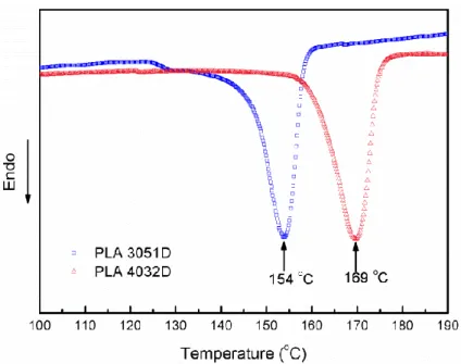
The SRP concept applied in this thesis follows earlier work on PP and PET and is based on highly oriented PLA tapes and thin layers of isotropic PLA films, which are combined using a film-stacking technique into a „brick-and-mortar‟ structure (see Figure 1.3). The reinforcing tape is solid-state drawn under tension at temperatures just below the melting point of the polymer to orient the polymer chains along the tape‟s axis to improve strength and stiffness. This layer is then sandwiched between two thin outer layers of a PLA matrix with a lower melting point (154 oC) than the reinforcing tape (169 oC). During hot-pressing, the matrix layers are selectively melted to weld the tapes together to form a composite structure, while retaining the mechanical properties of the tape.
Figure 1.3 Schematic of the hot compaction process.
26
applications as a high performance bio-based engineering plastic. However, in order to be successful in more demanding applications the important issue regarding degradation during the product‟s lifetime needs to be addressed. It is for this reason that monitoring of degradation levels during usage could prove to be of a vital interest for this type of materials.
In the second part of the thesis, the aim is therefore to develop a range of multifunctional engineering bioplastic systems with improved performances (mechanical and electrical), functionalities (sensing properties), and processability. Carbon nanotubes (CNTs) have gained considerable attention with their outstanding properties. The combination of high Young‟s modulus and tensile strength, excellent thermal and electrical conductivity in combination with their low density and high aspect ratio has made them ideal candidate fillers for a whole new range of multifunctional nanocomposites. These opportunities include the use of CNTs as conductive filler in insulating polymer matrices and as reinforcement in structural materials [11-13]. Interestingly, it has been shown that the electrical conductivity of CNT networks in polymer matrices are affected by stimuli such as temperature [14], gases [15], vapour [16], mechanical stress and strain [17,18], pH [19], and liquids [20]. Generally, the underlying mechanism is that the introduced external stimuli results in a deformation of the CNT percolation network, thus leading to a change in electrical conductivity of the composites. Hence, measuring changes in the electrical resistivity of a compound can be used to „sense‟ or monitor its structural status. Here we will attempt to use such conductive CNT networks to monitor biodegradation in the PLA matrix, as it is expected that polymer degradation will change the mobility of the CNTs in the polymer matrix, leading to changes in the network and through this changes in electrical
27 properties.
It is worth mentioning that in order to keep the environmental impact and carbon footprint as low as possible, Nanocyl (Belgium) has been working on the production of CNTs using biosourced hydrocarbon, methane, ethanol and camphor in another work package of the project HiBioPol. However, the CNTs used in the present work are a non-biosourced commercial available product.
Based on the above facts, the main goals of the thesis are:
• To understand the structure-property relationships of PLA during solid-state drawing and to optimize their mechanical properties via processing
• To tackle the high brittleness, low heat resistance and unsatisfactory tensile properties of neat PLA through the development of SR-PLA composites
• To produce conductive PLA/CNT tapes with high strength and modulus
• To provide real-time information of the degree of degradation of PLA through the use of CNT as sensors
• To investigate the market potential of SR-PLA composites
1.3 Scope of the thesis
This project describes the processing and properties of multifunctional bio-based PLA composites. The thesis is divided into two parts. Part I focuses on the manufacturing and properties of SR-PLA composites. Chapter 2 gives a comprehensive overview of the literatures of PLA composites and SRP‟s. The development of a high performance PLA tape as reinforcement is essential in imparting superior mechanical properties into resulting SR-PLA composites. Therefore, the influence of the applied draw ratio and
28
drawing temperature on the morphology and mechanical properties are presented in Chapter 3. Then, an investigation of interfacial, mechanical and thermal properties of resulting SR-PLA composites are carried out in Chapter 4. In Part II, the discussion focuses on the development and functionalization of PLA/CNT nanocomposites. After a literature review in Chapter 5, Chapter 6 describes an attempt of reinforcing PLA using CNTs through a melt-compounding process followed by solid-state drawing. The draw ratio dependency of mechanical and electrical properties in these nanocomposites is studied. Chapter 7 successfully explores a novel in-situ degradation monitoring system based on PLA/CNT films. Finally, Chapter 8 summarizes the findings of this project together with some ideas for future research, which could lead on from this project. A marketing study is also performed to determine whether commercial exploitation opportunities exist for the SR-PLA technology developed.
1.4 References
1. E. Commission, Directive 2000/53/EC of the European Parliament and of the Council of 18 September 2000 on end-of-life vehicles. Official Journal of the European Communities, L, 2000. 269: p. 34-269.
2. S. Ebnesajjad, Handbook of biopolymers and biodegradable plastics: properties, processing and applications. William Andrew, 2012.
3. T. Mukherjee, and N. Kao, PLA based biopolymer reinforced with natural fibre: a review. Journal of Polymers and the Environment, 2011. 19(3): p. 714-725.
4. P. K. Bajpai, I. Singh, and J. Madaan, Development and characterization of PLA-based green composites: A review. Journal of Thermoplastic Composite Materials, 2012: p. 0892705712439571.
5. S. Halliwell, End of life options for composite waste-recycle, reuse or dispose. National Composites Network report, 2006.
6. J. L. Thomason, L. Yang, C. C. Kao, and P. Jenkins, Regeneration of the performance of glass fibre recycled from end-of-life composites or glass fibre waster. International Glass Fiber Symposia,2012.
7. E. Sáez-Rodríguez, L. Yang, and J. L. Thomason, Regeneration of thermally recycled glass fibre for cost-effective composites recycling: Increasing the strength of thermally conditioned glass fibres using cost effective ReCoVeR treatments.16th European Conference on Composites Materials,2014.
29
in Polymer composites-polyolefin fractionation-polymeric peptidomimetics-collagens. 2013, Springer. p. 1-76.
9. C. Purac, PLA lifecycle closing the loop with PLA. 14 October 2014; Available from: http://www.corbion.com/bioplastics/about-bioplastics/pla-lifecycle.
10. V. Piemonte, S. Sabatini, and F. Gironi, Chemical recycling of PLA: A great opportunity towards the sustainable development? Journal of Polymers and the Environment, 2013.
21(3): p. 640-647.
11. H. Deng, R. Zhang, C. T. Reynolds, E. Bilotti, and T. Peijs, A novel concept for highly oriented carbon nanotube composite tapes or fibres with high strength and electrical conductivity. Macromolecular Materials and Engineering, 2009. 294(11): p. 749-755. 12. Q. Zhang, S. Rastogi, D. Chen, D. Lippits, and P. J. Lemstra, Low percolation threshold in
single-walled carbon nanotube/high density polyethylene composites prepared by melt processing technique. Carbon, 2006. 44(4): p. 778-785.
13. Q. Wang, J. Dai, W. Li, Z. Wei, and J. Jiang, The effects of CNT alignment on electrical conductivity and mechanical properties of SWNT/epoxy nanocomposites. Composites Science and Technology, 2008. 68(7): p. 1644-1648.
14. J. R. Wood, Q. Zhao, M. D. Frogley, E. R. Meurs, A. D. Prins, T. Peijs, D. J. Dunstan, and H. D. Wagner, Carbon nanotubes: from molecular to macroscopic sensors. Physical Review B, 2000. 62(11): p. 7571-7575.
15. J. K. Abraham, B. Philip, A. Witchurch, V. K. Varadan, and C. C. Reddy, A compact wireless gas sensor using a carbon nanotube/PMMA thin film chemiresistor. Smart Materials and Structures, 2004. 13(5): p. 1045-1049.
16. B. Kumar, M. Castro, and J-F. Feller, Poly(lactic acid)–multi-wall carbon nanotube conductive biopolymer nanocomposite vapour sensors. Sensors and Actuators B: Chemical, 2012. 161(1): p. 621-628.
17. R. Zhang, M. Baxendale, and T. Peijs, Universal resistivity-strain dependence of carbon nanotube/polymer composites. Physical Review B, 2007. 76(19): p. 195433.
18. E. Bilotti, R. Zhang, H. Deng, M. Baxendale, and T. Peijs, Fabrication and property prediction of conductive and strain sensing TPU/CNT nanocomposite fibres. Journal of Materials Chemistry, 2010. 20(42): p. 9449-9455.
19. N. Ferrer-Anglada, M. Kaempgen, and S. Roth, Transparent and flexible carbon nanotube/polypyrrole and carbon nanotube/polyaniline pH sensors. Physica Status Solidi (b), 2006. 243(13): p. 3519-3523.
20. P. Pötschke, T. Andres, T. Villmow, S. Pegel, H. Brünig, K. Kobashi, D. Fischer, and L. Häussler, Liquid sensing properties of fibres prepared by melt spinning from poly(lactic acid) containing multi-walled carbon nanotubes. Composites Science and Technology, 2010. 70(2): p. 343-349.
30
31
Chapter 2.
Literature review
2.1 Poly(lactic acid) (PLA): A sustainable bioplastic
Polymers derived from renewable resources are now considered as promising alternatives to traditional petro-based polymers as they fulfil current environmental concerns. Poly(lactic acid) (PLA) is one of the most promising bioplastic because of its attractive mechanical properties, low emission of greenhouse gases, low amount of energy used for production, potential biodegradability and high industrial production capacity.
The first attempt to prepare PLA was ascribed to Carothers (at DuPont) in 1932 as a low molecular weight product by heating lactic acid under vacuum [1]. However, the initial uses were limited to medical and pharmaceutical applications due to its limited capacity, high manufacturing cost, and low molecular weight. There is a sharp rise in the development and commercial marketing of PLA in the last two decades, since the advancement in the fermentation of dextrose obtained from corn dramatically reduced the cost to make monomer lactic acid [2]. During the last years of 20th century several companies have made attempts to produce PLA in industrial scale. NatureWorks Llc. (USA) announced a production capacity of about 140,000 ton/year of PLA under the name IngeoTM, mainly for the commodity market, such as film and fibres for packaging, housewares, and clothing.
32
PLA belongs to the family of aliphatic polyesters with the basic building block of lactic acid. The monomer lactic acid has two optically active stereoisomers: dextro- (D-) and
levo- (L-) (Figure 2.1). Natural fermentation generally yields a mixture of 99.5% of the L-isomer and 0.5% of the D-isomer. The two isomers have identical physical properties,
with the exception that of the L-isomer rotates the plane of polarized right clockwise
while the D-isomer rotates it anti-clockwise.
Figure 2.1 Two stereoisomers of lactic acid.
There are two major routes to produce PLA from the monomer lactic acid (Figure 2.2). The conventional process is by the polycondensation of lactic acid. This process is carried out under high vacuum and high temperature. Solvent is used to extract by-products. This method leads to low molecular weight PLA due to difficulties of removing water and impurities [3]. The second method is ring-opening polymerization through the lactide intermediate. This method results in a higher molecular weight polymer and uses milder conditions [4].
33
Figure 2.2 Polymerization routes to PLA [3].
Production of PLA via the lactide route allows the possibility of modifying the physical properties by controlling the stereochemical structure of the polymer [5]. The ratio of D-
and L-isomers and their distribution along the polymer backbone can influence the
molecular weight, crystallinity, and melting temperature of the end product [3]. Since the D-form is normally considered as defects in fermented lactic acid, fully amorphous
materials can be produced by the inclusion of relatively high D-lactide content (> 15%)
[6], whereas highly crystalline materials can be achieved when the D content is low (<
2%) [7]. The crystallinity and melting temperatures of both pure poly-L-lactide (PLLA)
and poly-D-lactide (PDLA) are about 37% and 175-178 ºC, respectively.
Representations of PLA polymer chains having different ratios and distributions of the
D- and L- isomers are shown in Figure 2.3. Different melting temperatures of PLA,
varying from 130 oC to 220 oC, can be obtained [6]. PLLA having only L-lactic units has
a melting temperature of 180 ºC and is shown in the upper row of Figure 2.3. A blend of PLLA and PDLA can lead to a polymeric stereocomplex with melting temperature as
34 high as 220 oC (See the bottom row of Figure 2.3).
Figure 2.3 Examples of molecular configurations of PLA obtained through combining
the two lactic acid isomers in varying proportions [3].
The mechanical properties of lactic acid based polymers can be varied to a large extent depending on not only stereochemical structures, but also crystallinity, molecular weight, crystalline orientation, the processing history, and so on. Generally, semi-crystalline PLA is preferred to the amorphous PLA when high mechanical properties are desired. Semi-crystalline PLA has an approximate tensile modulus of 3 GPa, tensile strength of 50-70 MPa, flexural strength of 100 MPa, and strain at break of about 4% [8]. It has been shown that tensile strength and modulus of PLA increases by a factor of two when the molecular weight increases from 50 to 100 kDa [9]. A further increase in molecular weight to 300 kDa seemed not to influence the properties of the polymers significantly. Grijpma and Pennings [10] investigated the importance of the crystalline fraction in the toughness of PLA. They varied crystallinity of PLA copolymers by introducing 0-15 mol.% D-lactide. The impact strength (37 kJ m-2) reached maximum at D-lactide content
of 0.5 mol.% and a heat of fusion of 60 J g-1. They explained that this optimum in mechanical properties is reached at a point where the entanglement density is relatively
35
high and the crystallinity is large enough to make the effect of physical cross-linking on the brittle tensile strength. Superior mechanical properties have also been achieved by stereocomplexation of enantiomeric PLAs, which was ascribed to formation of stereocomplex crystallites giving intermolecular cross-linking [11]. There is no significant differences in mechanical properties of polymers of similar molar masses, but prepared by different polymerization processes [12].
2.2 Natural fibre reinforced PLA composites
In comparison with commodity polymers such as polyethylene (PE), polypropylene (PP), polystyrene (PS) and poly(ethylene terephthalate) (PET), the mechanical properties of semi-crystalline PLA are attractive, particularly its high Young‟s modulus, making it as an excellent substitute for commodity polymers in short-time packaging. However, due to its high brittleness and low heat deflection temperature (HDT), PLA has not yet gained full market acceptance as an engineering resin.
One possible strategy to improve the mechanical and thermal properties of PLA has been through the addition of natural fibres (NFs) to make so-called „green composites‟ [13]. NFs have advantages such as low cost, high specific strength and modulus, biodegradability and renewability compared to glass fibres (GFs).
Dicker et al. [14] used Ashby plots for a comparative evaluation of the mechanical
properties of various fibres and their composites as shown in Figure 2.4. It can be seen that NFs and GFs are comparable in terms of specific stiffness and specific strength. However, a wide gap appears when comparing the mechanical properties of composite materials constructed from each of these fibres. There are several reasons for this
36
disparity between the properties of the raw fibres and their composites. One reason is the poor thermal stability of NFs. Wielage et al. [15] showed that the tensile properties
of NFs can decrease by as much as 60% when the fibres were processed for 60 min at 220 oC. Moreover, the poor compatibility between hydrophilic natural fibre and hydrophobic polymer matrix is also responsible. Numerous attempts have been made to overcome this issue, which will be discussed in details in the following paragraphs.
37
Table 2.1 Comparison of the mechanical properties of PLA-based green composites.
Author (year) Fibre type (proportion) Tensile strength
[MPa] Young’s modulus [GPa] Impact strength increase in % * Oksman et al. [18] (2003) Nishino et al. [19] (2003) Plackett et al. [20] (2003) Huda et al. [21] (2005) Li et al. [22] (2006) Bax et al. [23] (2008) Bax et al. [23] (2008) Cheng et al. [24] (2009) Bledzki et al. [16] (2009) Bledzki et al. [16] (2009) Bledzki et al. [17] (2010) Flax (30 wt.%) Kenaf (70 vol.%) Jute fibre (40 wt.%)
Recycled newspaper cellulose fibre (30 wt.%) Bamboo fibre (30 wt.%)
Cordenka rayon fibre (30 wt.%) Flax (30 wt.%)
Chicken feather fibre (5 wt.%) Man-made cellulose (30 wt.%) Abaca fibre (30 wt.%) Jute fibre (30 wt.%) 53 62 93.5 47.7 45 58 54 55 91 74 82 8.3 6.3 8.7 6.3 3 4.9 6.3 4.2 5.8 8.2 9.6 -27% - -7% -49% - 350 -45% - 260 140 20 * Because the test methods presented in different papers differ from each other, percentage change values compared to the value for pure matrix given in every particular work are presented. Values are calculated by using information which was not given in numeric values but in figures.
38
A comparative study on the mechanical properties of various NFs reinforced PLA composites is given in Table 2.1. The different extent of reinforcement accounts for the type of fibre used and its homogenization to the matrix. The composites with flax show higher strength and modulus within the NFs group, since the flax is characterized by higher mechanical properties than for example bamboo. The other factors that affect the mechanical strength include fibre diameter, length and aspect ratio. The diameters of NF bundles range considerably more than 50 μm. Man-made cellulose occurs in most cases as elementary fibres with a diameter of only 12 μm. Increasing fibre diameter affects the aspect ratio and thus decreases the mechanical performance of the composites. Bledzki and Jaskiewicz [16] pointed out that the highest aspect ratio of the man-made cellulose fibre is the main cause for its enhanced mechanical properties. Similarly, jute fibre bundles undergo separation during processing, allowing a better distribution and a favourable diameter for improved mechanical properties [17].
With regards to tensile strength, it is very sensitive to the fibre/matrix interfacial adhesion. When an external load is applied to composites, the load is transferred from the matrix at the surface of composites to the fibres nearest the surface and continues from fibre to fibre via matrix and interface. Therefore, a weak interface induces an ineffective load distribution and the mechanical properties of the composites are impaired. On the contrary, a strong interface can assure an efficient load transfer to fibres even after several fibres are broken, with a consequent improvement of composite mechanical behaviour. It is therefore clear that optimization of interfacial adhesion is necessary in order to improve the overall mechanical properties.
39
property will facilitate a better adhesion. Nevertheless, long fibre pull-outs and clean fibre surface of the PLA/flax composites as observed by Oksman et al. [18] proves a
poor adhesion between the fibre and the matrix. Modifications of fibres were extensively reported in literatures. Mukherjee and Kao [25] reviewed the effect of fibre surface treatment on the fibre-matrix adhesion and mechanical properties of NFs reinforced PLA composites. Huda et al. [21] examined the effect of the addition of
silane coupling agent and talc on the thermal and mechanical properties of PLA/recycled newspaper composites. The silane treated talc reinforced PLA/recycled newspaper hybrid composites flexural and impact strength was found to be significantly higher than that of those made without silane coupling agent. The silane treated hybrid composites showed improved properties such as a flexural strength of 132 MPa and a flexural modulus of 15.3 GPa, while the untreated composites exhibited flexural strength and modulus values of only 77 MPa and 6.7 GPa, respectively.
Interestingly, Juntaro et al. [26] successfully attached nano-sized bacterial cellulose (BC)
onto sisal fibres and then incorporated them into PLA. The presence of nanofibres led to a rise in interfacial adhesion with PLA, thus significantly improved both fibre-dominated and interface-dominated properties of these hierarchical composites.
The impact strength of a composite depends on the type of fibre and is often inversely proportional to its interfacial adhesion with the matrix. Bax et al. [23] prepared
Cordenka reinforced PLA composite and reported a maximum impact strength of 72 kJ m-2 with the addition of 30 wt.% fibres, which is approximately 4.5 times that of pure PLA. This value is also higher than the impact strength of PP/flax composite (32 kJ m-2) as reported in the literature [27]. Bledzki et al. [16] also obtained a 260% increase in
40
impact strength for man-made cellulose reinforced PLA composites. On the other hand, a decrease in impact strength was observed in case of jute fibres by Plackett et al. [20].
Similar results were observed by Oksman et al. [18] and Bax et al. [23] for PLA/flax
composites. This can be explained by the relatively strong fibre-matrix adhesion leading to a more brittle failure behaviour in PLA/flax composites as compared to PLA/Cordenka composites.
Improved HDTs are also observed in NFs reinforced PLA composites mainly due to increased crystallinity, modulus and/or the improved adhesion between matrix and fibre. Huda et al. [28] reported that surface-treated kenaf fibre reinforced laminated
composites possessed higher storage moduli, impact strength and HDT than pure PLA resin but at the expense of tensile strength.
To date, a number of composite manufacturers have introduced NFs reinforced PLA composites in their product range. FKuR (Germany) has developed wood reinforced PLA compounds (FIBROLON), which can be extruded or injection moulded into complex profiles, panels, and hollow profiles and/or into components for automotive interiors. Products of wood and biodegradable polyesters are also developed by FuturaMat (France) under the trade name BioFibra® in grades suitable for injection moulding, extrusion, or thermoforming. Large scale use of PLA/NFs composites in automotive applications have been reported as well. Toyota, for example, uses kenaf fibre reinforced PLA composites for its Prius hybrid car interior parts [29].
However, there are some major drawbacks which could limit the commercial adoption of these fibres as reinforcements in composites.
41
polymer matrix. Although chemical modification of fibres can potentially solve this issue, large amounts of hazardous chemicals are typically involved and chemical waste must be disposed appropriately.
Variability in fibre properties is another major issue to be resolved if these materials are used in structural applications where durability must be accurately predicted. Due to NFs being obtained from natural sources, crop variety, factors including seed density, soil quality, fertilization, field location, fibre location on the plant, climate and harvest timing could all induce variability in properties, such as fibre shape, length and chemical composition.
Furthermore, Summerscales et al. [30] compiled the results of quantitative life cycle
assessment (QLCA) from Dissanayake et al.’s work. They found that the total energy required for flax using low energy agricultural processes was even greater than glass fibres. Therefore, the „green‟ claim for NFs composites may only be appropriate when the best practice is adopted in the growth, separation and processing of NFs, at the same time the durability of NFs composites is comparable to GFs composites.
Although the use of NFs to reinforce PLA seems at first to be an environmentally sound approach as they are renewable, there are some issues with respect to end-of-life scenarios for these composites. In the case of mechanical recycling their relatively poor thermal stability may lead to severe additional thermal degradation of the composites during subsequent reprocessing steps. Furthermore, the recycling process of a traditional composite usually requires high technology and high cost due to the difficult separation of the fibre from polymer matrix [31]. Actually, the introduction of any „foreign‟ filler is in conflict with the basic idea behind recycling and monomaterial
42 products.
2.3 Self-reinforced polymer composites
2.3.1 Self-reinforced polymer composites
A promising approach to composite recycling is the concept of „self-reinforced polymer‟ composites (SRPs) or „all-polymer‟ composites, in which a polymer matrix is reinforced with oriented fibres or tapes of the same polymer. The absence of „foreign‟ reinforcements means enhanced fibre-matrix interfacial adhesion and more importantly, full recyclability without the need for separation of fibre and matrix. The concept was first presented by Capiati and Porter [32] using oriented PE reinforcement and PE matrix with different melting temperatures. In following several decades, it has been successfully transferred to a range of polymers using various consolidation technologies.
The most frequently used technology to manufacture SRPs is film-stacking, where similar polymers with different melting temperatures are used to achieve melting of one phase to yield matrix, while retention of another phase to yield reinforcement. Examples of this method include the work of Capiati and Porter [32], Kazanci et al. [33], Barany
et al. [34], Houshyar et al. [35], and more recently Gong and Yang [36]. This method
has many advantages, such as ease of production, good matrix distribution, can be applied to commercial polymer fibres or fabrics and films. The processing window can be large by selecting similar polymers but with very different melting temperatures. A wide variety of thin polymer films means that fibre volume fractions can be fairly well controlled. Other approaches for introduction of a polymer matrix phase amongst
43
polymer fibres include melt impregnation [37], powder impregnation [38], and solution impregnation [39, 40]. A low viscosity of the polymer matrix is crucial for good impregnation, where reinforcement fibres/tapes should be surrounded by matrix without voids. However, compared to non-crosslinked thermosets, the melt viscosities of thermoplastics are usually 3-6 orders higher, which means it is more difficult for thermoplastics to achieve a good matrix distribution by melt-impregnation.
Figure 2.5 Consolidation of a SRPs from homogenous fibres by a hot compaction
technology [41].
In 1993, Ward and others at the University of Leeds described a simple but innovative processing method, called „hot-compaction‟ [42], which has been investigated for a range of polymers [43-46]. Here an assembly of oriented polymer fibres or tapes is heated to a critical temperature, while held under pressure, such that a thin skin on the
44
surface of each oriented element is „selectively melted‟, creating a matrix phase. On subsequent fast cooling, the molten material recrystallises to form the matrix of the composite, with the remaining fraction of the original oriented phase acting as the reinforcement. This process is shown schematically in Figure 2.5. The first hot-compaction studies were carried out on unidirectional aligned melt-spun PE fibres [42]. They found that a maximum modulus of 36 GPa was obtained at the optimum compaction temperature of 136 oC with a processing window of ± 2 oC. DSC results showed that the optimum sample had around 15% of the molten and recrystallized
Figure 2.6 Etched micrographs from unidirectional melt-spun CERTRAN PE fibres. (a)
SEM picture of a transverse section of compacted fibres. (b) TEM picture of an
interstitial lamellar region and its junction with adjacent fibres.
matrix phase. In a later study [47], SEM and TEM of etched compacted samples showed how the recrystallized material fills the interstices in the close packed fibres. The molten skins recrystallized epitaxially on the surfaces of the un-molten portion of the fibres, as shown in Figure 2.6. Conditions were found for the successful compaction of a wide range of polymer fibres and tapes, including gel-spun PE fibres [41, 48], PET fibres [44], liquid crystalline polymer fibres [49] and fibrillated PP tapes [50]. Recent efforts have mainly focused on PP and this material is now commercially available under the
45
trade name Curv®. While it is a very elegant concept, the hot compaction process is clearly temperature sensitive. The need for unique and well-controlled composite processing routes may mean that these composites are more expensive to manufacture and more sensitive to manufacturing parameters than conventional composites.
In the early 2000s, Peijs and coworkers developed a co-extrusion technique based on PP [31]. The key development is the concept of co-extruding multilayered tapes consisting of a PP homopolymer core covered by a thin PP copolymer skin with a lower melting temperature (see Figure 2.7). Subsequent solid-state drawing of these co-extruded tapes leads to a large increase in mechanical properties. These tapes can be woven into fabrics, and then further consolidated into sheets. An example of SRPs produced by using coextruded tape technology is shown in Figure 2.8.
Figure 2.7 Co-extrusion technology is used for the development of high-performance
PP tapes. These tapes consist of a highly oriented core (B) and a thin polymer skin (A)
46
Figure 2.8 Optical micrograph of a cross-section of a co-extruded PP woven tape-based
SRP [51].
In this way, the reinforcement and matrix phase of the composite are produced at the same time; hence there is no need for a separate impregnation step when manufacturing the composites. The bonding between fibre or tape and matrix is achieved during co-extrusion. The processing temperature window could be widened to as much as 30
o
C. Cabrera et al. [52] studied the effect of consolidation temperature on the flexural
stiffness of unidirectional SR-PP produced by using co-extruded tape. They found that over the range of consolidation temperatures studied (140-170 oC), there was no significant effect of consolidation temperature on the flexural stiffness of the laminates, indicating that this wide temperature window would make composites based on co-extruded tapes less sensitive to thermal relaxation during hot-consolidation than mono-extruded tapes with a much narrower processing temperature window. The other main advantage of using co-extruded tapes is that the matrix material can be evenly distributed during composite consolidation. The volume fractions of reinforcement in these composites was extremely high (~ 90% or greater), while various parameters
47
could be used to adjust mechanical [53, 54] and interfacial properties [55].
Because of the large processing window, a wide range of composite fabrication techniques were demonstrated by Cabrera et al., including filament winding [56],
non-isothermal stamping [57] and the creation of sandwich panels [58]. Although the temperature processing window is quite wide, the characteristics of the final composite, such as static and dynamic mechanical properties [59, 60], fatigue resistance [61], impact resistance [62] and porosity [63], are very dependent on these processing parameters. This allows the composite properties to be tailored to the final application. Following the commercialization of SR-PP composites using co-extruded tape technology as the product PURE®, this idea was later also applied to create composites based on PET. Zhang and Peijs reported the use of co-extruded PET yarns with a copolyester skin layer to facilitate easier processing, resulting in composites with a fibre volume fraction of ~ 70% [64].
2.3.2 Self-reinforced poly(lactic acid) composites
The creation of SRPs comprising various bioabsorbable precursor polymer fibres was also investigated mainly for medical applications, including polyglycolide (PGA), polyglycolide-lactide copolymer and PLA. This section will review the production and properties of the precursor PLA fibres first, followed by the development of SR-PLA composites to date.
2.3.2.1 PLA fibre
The development of high-stiffness and high-strength PLA fibres is essential in imparting superior mechanical properties onto the resulting SR-PLA composite. The mechanical
48
properties of fibres can be increased via molecular orientation during spinning and drawing, and the most commonly used methods of producing PLA fibres are melt spinning and solution spinning. The following paragraphs will review on the production of PLA fibres by both methods, along with correlations between structure and properties of the fibres. Comprehensive data on PLA fibre spinning are presented in Table 2.2.
In general, solution-spun fibres are superior to melt-spun fibres from the standpoint of mechanical properties. This is attributed to the lower chain entanglement of polymer molecules in the solution state as compared to the melt state. For instance, Penning et al.
[65] reported that dry spinning followed by hot drawing resulted in low crystallinity fibres having a tensile strength of 1 GPa, whereas fibres prepared from melt spinning followed by hot drawing had considerably lower strengths, ranging from 0.19 GPa for completely amorphous copolymers to 0.53 GPa for PLA homopolymer. Fambri et al.
[66] were able to obtain fibres with tensile strengths and modulus of 1.1 GPa and 10 GPa, respectively, with a PURAC brand biomedical material having Mv = 660,000.
Similarly, Leenslag et al. [67] produced fibres with tensile strengths and modulus of 2.1
GPa and 16 GPa from PLA with Mv = 900,000. The main drawbacks are that solvents
such as chloroform and toluene are necessary, and the production speed is rather low.
Table 2.2 Properties of oriented PLA fibre/tape.
Author (year) Method Material Strength/ modulus [GPa] Comment Eling et al. [68] (1982) Melt spinning and drawing PLA 0.50 / 7.0 Initial Mv < 3×10⁵
49 [69] (1997) and hot drawing Drawing at 160 oC; Crystallinity ~ 59.2% Mezghani et al. [70] (1998) High speed melt spinning
PLA 0.38 / 6.0 Take-up velocity ~2000 m/min; Initial Mn=105,300 Daltons Extrusion temperature ~233 oC; Crystallinity ~ 42% Yuan et al. [71] (2001) Melt spinning and hot drawing PLA 0.53 / 5.2 DR=4.71; Initial Mv=4.95×10⁵ Drawing at 120 oC; Crystallinity ~61.9% Cicero et al. [72] (2002) Melt spinning and hot drawing PLA 0.38 / 3.2 DR=6; Initial Mn=47,600
Radiant heating levels ~75%; Crystallinity ~ 47% Sawai et al. [73] (2006) Solid-state coextrusion PLA 0.50 / 8.0 DR=14; Initial Mv=4.6×10⁵ Drawing at 170 oC; Crystallinity ~49% Leenslag et al. [67] (1987) Solution spinning and hot drawing PLA 2.1 / 16 DR=20; Initial Mv=9×10⁵ Chloroform/toluene mixtures as solvent Solution temperature 60 oC; Drawing at 204 oC Crystallinity ~53% Fambri et al. [66] (1994) Solution spinning and hot drawing PLA 1.1 / 10 Initial Mv=6.2×10⁵ Chloroform as solvent Drawing temperature 150-210 o C Table 2.2 (Continued)
Commercial PLA fibres are mainly produced by melt spinning. Generally, PLA fibres are produced by a two-stage process: first melt extrusion, and then solid-state hot drawing. Eling et al. [68] reported melt extrusion of PLA at 185 oC through a capillary,
50
of 7 GPa and tensile strength of 0.5 GPa. The investigation of Cicero et al. [72]
illustrates the two-step melt spinning of textile grade PLA. A maximum modulus and tensile strength of 3.2 GPa and 0.38 GPa were obtained respectively. Later, Cicero et al.
[74] investigated the crystalline morphology of PLA by small-angle X-ray scattering and atomic force microscopy. They proposed a representation of the molecular structure of PLA (Figure 2.9) where the alignment of microfibres along the fibre axis is determined by the draw ratio. The crystalline and amorphous regions form stacks within the microfibrils and the interfibrillar region is populated by amorphous chains. Fambri et al. [69] reported melt-spun PLA fibres with tensile modulus of 9.2 GPa and tensile
strength of 0.87 GPa. Yuan et al. [71] prepared PLA fibres by a two-step melt spinning
process. Results showed that Mv dropped sharply by 13-20% during pulverization and
by 39-69% during melt extrusion. The hot-drawing process had little effect on Mv of
PLA.
51
PLA filaments can be spun at high speed take-up velocities of up to 5000 m min-1 [70]. The crystallinity, birefringence, tensile strength, Young‟s modulus and yield strength, all exhibit maxima at take-up velocities between 2000 and 3000 m min-1. The boiling water shrinkage exhibits a minimum in this range, indicating that a stable morphology is developed through stress induced crystallization. The maximum tensile strength of these as-spun filaments was 385 MPa with a maximum modulus of 6 GPa.
2.3.2.2 Self-reinforced PLA composites
SR-PLA composites have been intensively studied since 1984, mainly for clinical use such as sutures, rods, screws and plates. Although few details regarding the exact processing routes were published in academic literature at that time, these bioresorbable composites were considered attractive as they possessed mechanical properties that exceeded most isotropic bioplastic, and could be naturally absorbed by the body over time, thus removing the need for surgical removal.
In 1988, Törmälä et al. successfully manufactured an SR-PLA composite with higher
strength than non-reinforced PLA for use in osteosynthesis devices [75]. The composite was produced by subjecting the fibres to elevated temperature and pressure. This process leads to more melting of the inner fibres but still allowed for the retention of some fibre orientation.
Improved strength and rigidity were widely reported in literature. Table 2.3 compares the mechanical properties of SR-PLA reported in literatures. Majola et al. [76]
successfully produced SR-PLA composite using sintering techniques at temperatures of 130-135 oC for (PDLLA/PLLA rods) and 162-174 oC (PLLA rods). The fibres were
52
Table 2.3 Mechanical properties of SR-PLA composite as reported in literature.
Authors (year) Materials Method Elastic
modulus [GPa] Tensile strength [MPa] Flexural modulus [GPa] Flexural strength [MPa] Shear strength [MPa] Törmälä (1992) [77] Törmälä (1992) [77] Majola et al. (1992) [76] Majola et al. (1992) [76] Haltia et al. (2002) [78] Wright et al. (2005) [79] Wright et al. (2006) [80] Li and Yao (2007) [81] PLLA PLLA PLLA PLLA/PDLA PLLA PLLA PLLA PLLA Hot drawing Sintering Sintering Sintering Hot drawing Hot compaction Hot compaction Film stacking - - - - - 5.4 - 2.3 - - - - - - - 43.6 10 - - - 5.6 5.6 5.6 - 300 250 250-271 209 210 - 150 - 220 96 94-98 102 - 143 - -
53
initially produced by hot drawing and m
![Figure 2.5 Consolidation of a SRPs from homogenous fibres by a hot compaction technology [41]](https://thumb-us.123doks.com/thumbv2/123dok_us/843190.2607236/44.892.367.607.388.845/figure-consolidation-srps-homogenous-fibres-hot-compaction-technology.webp)
![Figure 2.9 Supra-morphological model for two-step, melt-spun PLA [74].](https://thumb-us.123doks.com/thumbv2/123dok_us/843190.2607236/51.892.246.741.689.1014/figure-supra-morphological-model-step-melt-spun-pla.webp)