System Overview
System Overview
Contents
1. INTRODUCTION...5
2. SYSTEM ARCHITECTURE...6
2-1. GENERAL... 6
2-2. CENTRAL OFFICE (CO) CONFIGURATION... 7
2-3. CUSTOMER PREMISES EQUIPMENT CONFIGURATION... 8
2-4. FASTINTERNET: ONE SYSTEM FOR ALL TYPES OF SERVICE... 10
3. END TO END NETWORK ARCHITECTURE...10
3-1. GENERAL... 10
3-2. IP XDSL NETWORK... 12
3-2.1 IP Filtering ...12
3-2.2 Virtual LAN ...13
3-2.2.1 Using an Ethernet switch ... 13
3-2.2.2 Using the ATM Switch ... 14
3-2.3 IP Tunneling ...15
3-2.3.1 PPPoE... 16
4. IP POTS/UNIVERSAL SYSTEM ELEMENTS ...17
4-1. CUSTOMER PREMISES EQUIPMENT (CPE) ... 17
4-1.1 POTS and Universal CPE Splitters ...17
4-1.1.1 General... 17
4-1.2 Interfaces ...18
4-1.3 Physical/Environmental...18
4-1.4 Micro Filter ...18
4-1.4.1 General... 18
4-1.5 ADSL CPE Modem ...18
4-1.5.1 General... 18
4-1.5.2 Transmission... 18
4-1.5.3 Management... 19
4-1.5.4 Interfaces ... 19
4-1.5.5 Physical/Environmental ... 19
4-1.5.6 Integrated Bridge Functionality ... 19
4-2. CENTRAL OFFICE (CO) EQUIPMENT... 21
4-2.1 Splitter Shelf ...21
4-2.1.1 General... 21
4-2.1.2 Interfaces ... 22
4-2.1.3 Physical/Environmental ... 22
4-2.2 Central Office (CO) Splitter Module ...22
4-2.2.1 Interfaces ... 22
4-2.2.2 Environmental... 22
4-3. DSLAM SHELF AND MODULES... 22
4-3.1 DSLAM Shelf ...22
4-3.1.1 General... 22
4-3.1.2 Dimensions ... 23
4-3.1.3 Connectors ... 23
4-3.1.4 Power supply ... 23
4-3.2 ADSL line card ...23
4-3.2.1 General... 23
4-3.2.2 Transmission... 23
4-3.2.3 Management... 23
System Overview
4-3.2.5 Physical/Environmental ... 24
4-3.3 IP Concentrator...24
4-3.3.1 IP Concentrator Functionality... 24
4-3.3.2 Network Ports Configuration ... 26
4-3.3.3 Network Planning Considerations... 28
4-3.3.4 IP Concentrator Performance... 30
4-3.3.5 Interfaces ... 30
4-3.3.6 Physical/Environmental ... 30
4-3.4 Bridge card ...30
4-3.4.1 General... 30
4-3.4.2 Bridge Card Functions ...31
4-3.4.3 Bridge Card Performance ... 31
4-3.4.4 Interfaces ... 32
4-3.4.5 Physical/Environmental ... 32
5. NETWORK MANAGEMENT ...33
5-1. GENERAL... 33
5-2.ORVIEW™ DIRECT MANAGEMENT... 34
5-3. ORVIEW™ PLUS SNMP NETWORK MANAGEMENT... 35
5-3.1 SNMP Shelf Manager ...35
5-3.1.1 General... 35
5-3.1.2 Supported MIBs... 36
5-3.1.3 Element Management ... 36
5-3.1.4 Hot insertion capabilities ... 36
5-3.1.5 Alarms dry contacts ... 36
5-3.1.6 Software Download to Network Elements... 36
5-3.1.7 Physical/Environmental ... 36
5-3.2 OrView TM Plus SNMP Manager ...37
5-3.2.1 General... 37
5-3.2.2 Standard Reference... 37
5-3.2.3 Main Functionality... 37
5-3.2.4 Modular Architecture... 38
5-3.2.5 Graphical User Interface... 40
APPENDIX A SPECIFICATIONS: CO UNITS ...41
APPENDIX B SPECIFICATIONS: CPE UNITS ...43
System Overview
Figures
FIGURE 1 FASTINTERNET END-TO-END GENERAL NETWORK ARCHITECTURE... 7
FIGURE 2FASTINTERNET VOICE OVER DSL ARCHITECTURE... 7
FIGURE 3 FASTINTERNET CO CONFIGURATION... 8
FIGURE 4 TYPICAL RESIDENTIAL SUBSCRIBER EQUIPMENT CONFIGURATION... 9
FIGURE 5 TYPICAL SOHO EQUIPMENT CONFIGURATION USING ISDN INFRASTRUCTURE... 9
FIGURE 6 TYPICAL RESIDENTIAL OR SOHO EQUIPMENT CONFIGURATION USING MICRO FILTERS... 9
FIGURE 7 XDSL NETWORK ELEMENTS... 10
FIGURE 8 XDSL NETWORK... 11
FIGURE 9 ELEMENTS IN AN IP XDSL NETWORK... 12
FIGURE 10 IP FILTERING... 13
FIGURE 11 VLAN TAGGING USING ETHERNET SWITCH... 14
FIGURE 12 VLAN TAGGING USING AN ATM SWITCH... 14
FIGURE 13 LAYER 3 XDSL NETWORK ARCHITECTURE USING IP TUNNELING (PPTP OR L2TP) ... 15
FIGURE 14 A LAYER 2 XDSL NETWORK ARCHITECTURE USING PPPOE ... 16
FIGURE 15 CPE ... 17
FIGURE 16 DSLAM SHELF WITH IP CONCENTRATOR... 21
FIGURE 17 DSLAM SHELF WITH BRIDGE CARD... 21
FIGURE 18 CO SPLITTER SHELF... 21
FIGURE 19 SHELF CONCENTRATOR DAISY CHAINING... 26
FIGURE 20 SHELF CONCENTRATOR LOAD SHARING... 27
FIGURE 21 JOINT DAISY CHAIN AND REDUNDANCY... 28
FIGURE 22 DSLAM NETWORK MANAGEMENT SYSTEM... 34
FIGURE 23 ORVIEW™DIRECT SLOT MAP... 35
FIGURE 24 ORVIEW PLUS ARCHITECTURE... 39
System Overview
1. Introduction
Orckit Communications’ FastInternet™ system provides an integrated end-to-end solution for data
connectivity, Multi Media Services and high-speed Internet access services using xDSL transmission over an existing copper infrastructure.
FastInternet enables a service provider/operator to offer Virtual Private Networks (VPNs),
telecommuting, Video On Demand, in addition to high-speed Internet access and other broadband services to subscribers using xDSL technology at high-end performance and competitive cost. Based on Orckit’s extensive DSL deployment experience over the past decade, FastInternet’s
integrated networking capabilities offer these advantages:
• Connection to any backbone network (IP, FR as well as ATM through converters).
• Multiple and differentiated services to subscribers.
• Each user can be connected to multiple service providers and corporate networks.
• A comprehensive and scalable set of management tools through integration with Orckit’s OrView™ Plus Network Management System (NMS).
• Customer care and billing capabilities through integration with Portal’s Infranet system.
• Voice over DSL (VoDSL) solutions through integration with voice gateways for both American and European standards, from partners such as JetStream, CopperCom and TollBridge.
• Full network interoperability with first line Routers (as Cisco 6400), Layer 2 switches (Cisco Catalyst 5000/6500, NBase) and Broadband Access Servers (as Redback’s SMS).
• Full DSL interoperability with 3rd part CPE vendors, including USB CPEs.
At the access, FastInternet currently provides an Asymmetrical Digital Subscriber Line (ADSL)
interface based on a DMT modem, with rates of up to 8.192 Mbps downstream and 768 Kbps upstream. The ADSL system supports Full Rate G.dmt (ITU-T G.992.1, Annex A,B) and G.Lite standards (ITU-T G.992.2).
Both POTS and ISDN narrowband services are carried over the same copper wire in parallel to the DSL transmission using POTS and Universal splitters at central office and customer premises respectively. Distributed micro-filters can optionally also be used instead of splitters at the customer premises for simple installation of the DSL (POTS) equipment by the customer.
System Overview
2. System Architecture
2-1. General
FastInternet’s concept originates from a global network system perspective with emphasis on two key
factors: high performance xDSL transmissionand a cost effective end-to-end solution. FastInternet
system architecture is designed for maximum flexibility, answering a variety of requirements in terms of data rates, network load statistics, end customer interface, operator's network architecture and backbone network interfaces.
ADSL technology uses advanced digital modulation to transmit high data rates over a standard Telecom-grade twisted pair. The system includes optional splitters (at the subscriber and CO ends) which allow continuous, uninterruptible provisioning of analog POTS and ISDN lines in combination with data links without cross-interference between the two services. The use of fully passive splitters guarantees reliable, fault-tolerant lifeline telephone service.
FastInternet provides a high-speed data link between a customer unit (xTU-R) and the CO (xTU-C),
with a very flexible degree of concentration in the CO. The optimal concentration ratio is a key factor in achieving a low overall cost for the broadband service, taking into account all end-to-end equipment and operational cost. Concentration level is flexible, supporting different number of subscribers and changing concentration factors as load statistics and usage profiles change.
FastInternet’s modularity offers operators extensive flexibility at the shelf level:
• ADSL line cards
• POTS and Universal (POTS+ISDN) Splitters
• Packets transport over the xDSL link
• 10BaseT and USB interfaces at the Customer Premises
• Flexible concentration ratios
• Point-to-Point connectivity with Bridge cards or concentrated traffic with IP Concentrators
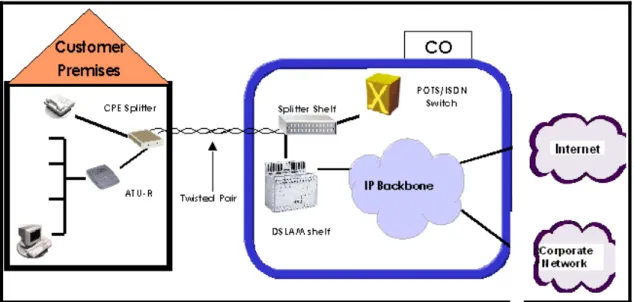
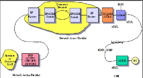
Figure 1 illustrates a FastInternet’s end-to-end network architecture. The system comprises Customer
Premises Equipment and Central Office equipment connected to the operator’s backbone network. The Voice over DSL end to end solution, offered by FastInternet in cooperation with voice gateway
System Overview
Figure 1 FastInternet End-to-End General Network Architecture
Figure 2 FastInternet Voice over DSL Architecture
2-2. Central Office (CO) Configuration
FastInternet provides an integrated solution for the CO end. However, different operators may employ
different network architectures. To allow for different strategies to be effectively combined with Orckit’s FastInternet solution, the CO DSLAM Modem Shelf/Rack supports a number of options.
An operator can provide broadband services to customers by connecting access networks and service providers via a backbone network or by directly connecting the DSLAM and the service provider’s equipment (e.g. ISP router).
System Overview
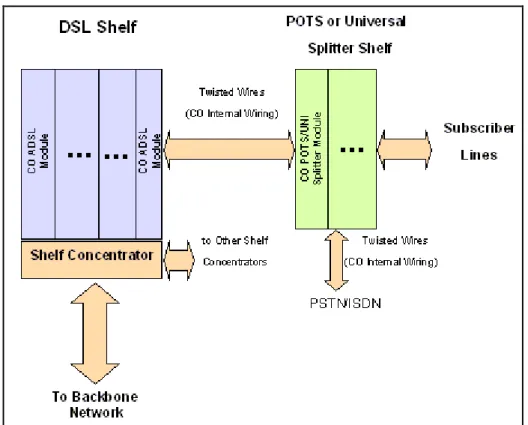
Figure 3 illustrates CO equipment configuration. CO equipment comprises a cluster of xDSL modems integrated with data concentration/access MUX equipment. xDSL modems provide high-speed DSL connectivity between the CO and customer premises. The shelf-level data concentration element enables a large number of subscribers to share a single common data interface to FastInternet. This
network interface, in the form of 10BaseT Ethernet, is further multiplexed with data coming from other shelves. The multi-shelf interface can in turn be connected to an industry standard router port if the operator’s network architecture contains routers at CO locations.
Orckit offers a range of network interfaces: from 2x10BaseT Ethernet interfaces per IP shelf
concentrator up to 24x10BaseT interfaces per Bridge card (for point-to-point connections), or 2xDS1 Interfaces per Frame Relay concentrator.
The two network interfaces of the concentrator can be used to either daisy-chain multiple DSLAM shelves into a single backbone interface or to split a shelf’s load (heavy load models) into two backbone interfaces (load sharing mode).
Two concentrators or two bridge cards can be inserted into a single shelf.
The concentrators in the same shelf can be used either as an online-standby redundant pair or to split the load of the shelf among four backbone interfaces (load sharing).
Figure 3 FastInternetCO Configuration
2-3. Customer Premises Equipment Configuration
Orckit’s FastInternet is designed to support the full range of customer (subscriber) configurations,
including a residential customer, a SOHO (Small Office - Home Office) and a general business. Each of these potential subscribers may run different applications, have different throughput requirements, an internal PC/LAN configuration, or need for POTS/ISDN overlay. Following are three diagrams illustrating typical subscriber equipment configurations:
System Overview
Figure 4 Typical Residential Subscriber Equipment Configuration
Subscriber Splitter
Subscriber ATU-R
Central Office Connection from the Line connector
of the Splitter to the Wall
Connection from the ADSL
connector on the Splitter to the ATU-R LAN
NT ISDN only
“S” interface
To user’s ISDN equipment
Figure 5 Typical SOHO Equipment Configuration using ISDN Infrastructure
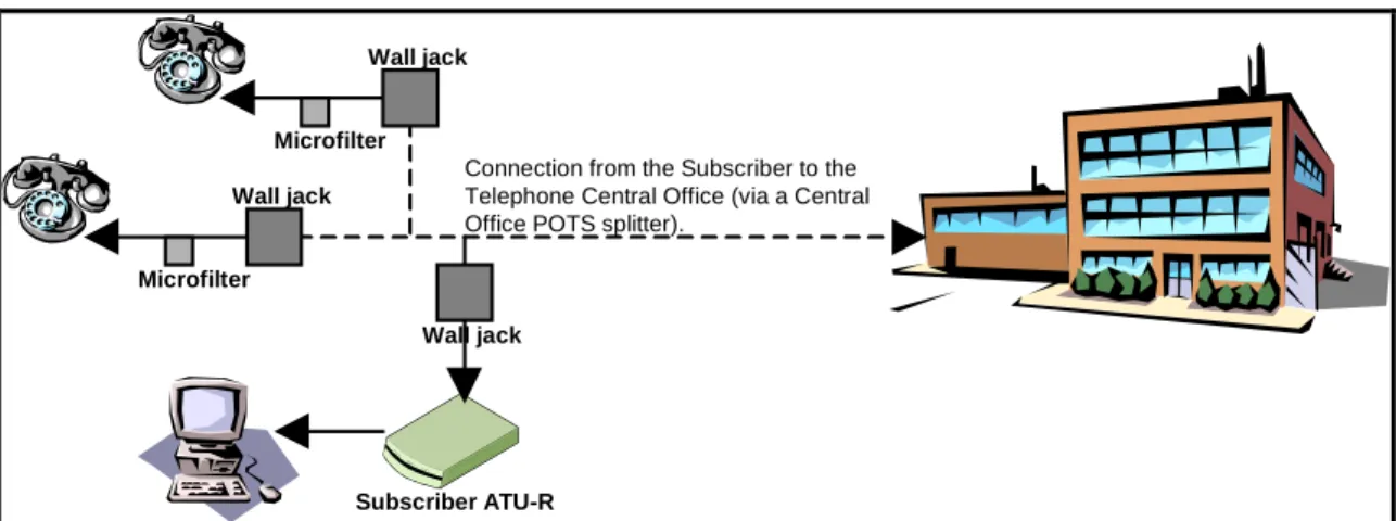
Subscriber ATU-R Wall jack Wall jack Wall jack Microfilter Microfilter
Connection from the Subscriber to the Telephone Central Office (via a Central Office POTS splitter).
Figure 6 Typical Residential or SOHO Equipment Configuration using Micro Filters
The home PC/business LAN is connected to the FastInternet CPE via either 10BaseT or USB interface.
The internetworking functionality of the xTU-R can be a Bridge, Router or Tunnel server. A CPE Splitter is implemented as an external stand-alone unit. An emphasis is put on extremely reliable operation of POTS or ISDN in all cases, including power failure or malfunction of the DSL modem.
System Overview
same copper wire as xDSL. xDSL’s reach with a POTS splitter is on average 10-15% better than with a Universal Splitter. However, using only Universal Splitters for a POTS-ISDN installation significantly simplifies both installation and subscriber migration from POTS to ISDN.
2-4.
FastInternet:
One System for All Types of Service
One of the great benefits of FastInternet is its superb flexibility as far as services are offered. An
operator can initiate a service and then go on to change the service without re-installing a new system. Specifically, FastInternet enables the following migrations (smoothly, on a per-user basis, without the
need to upgrade the whole network at once):
• IP over Ethernet to IP over Frame Relay service migration and vice versa
• Ethernet to USB user interface migration
• POTS to ISDN narrowband service migration can be done transparent to the broadband service over the same pair
FastInternet’s unique STAR Backplane Architectureat the CO allows:
• Switching between Ethernet and Frame Relay interface without a change in the xDSL line cards, CPE modems or shelves
• Switching between concentration mode and point to point mode (Bridge card-based) without a change in the xDSL line cards, CPE modems or shelves
• Switching xDSL line cards without change in shelves or concentration
• Switching between POTS and ISDN without change in shelves or concentrators
• Improving load statistics to decrease or increase amount of bandwidth per central office without changing of the shelves or line cards.
These issues are important at the implementation/mass deployment stage and at a later service stage.
3. End to End Network Architecture
3-1. General
Two examples of xDSL network addressed applications are: 1. High Speed Internet Access
2. Remote LAN Connectivity (telecommuting, VPN)
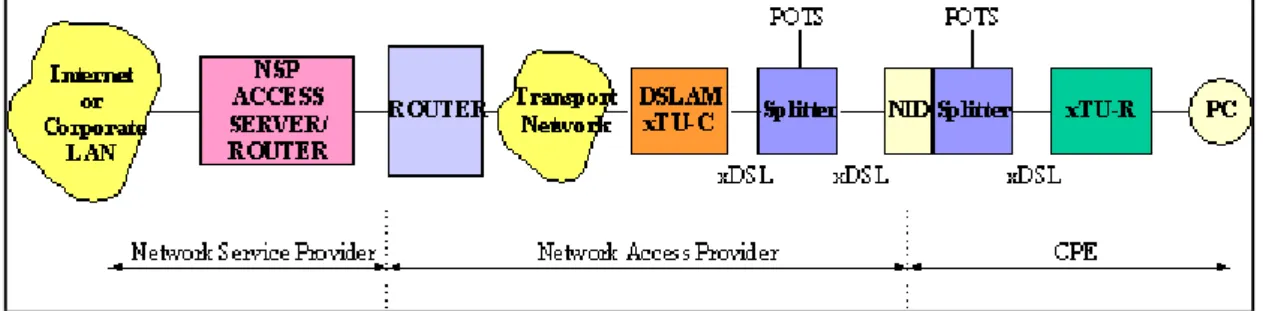
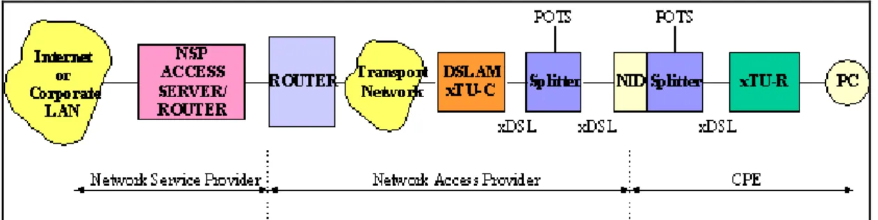
For both applications, the xDSL network operates the same way. In addition, in both cases a lifeline POTS/ISDN service is optionally available. Figure 7 illustrates the elements in an xDSL network. This architecture will be discussed in detail in the following section.
System Overview
The network is divided into three distinct segments:
1. Network Service Provider (NSP)
The Network Service Provider provides the gateway to a network (either the Internet or a Corporate LAN Intranet).
2. Network Access Provider (NAP)
The Network Access Provider (NAP) provides transport from the customer premises to the NSP.
3. Customer Premises Equipment (CPE)
CPE is the equipment at the customer premises required to support Internet Access via xDSL.
Lifeline POTS/ISDN is provided in the xDSL network. A splitter at the customer premises and at the Central Office extracts the POTS /ISDN lifeline. Apart from the Internet or Intranet itself, the data segment of an xDSL network is composed of at least three distinct parts as shown in Figure 8:
System Overview
The customer segment of the network consists of one or more PCs attached to an xTU-R modem. The modem transmits an xDSL signal to a twisted pair. The Network Access Provider (NAP) terminates the xDSL signal once it reaches the ATU-C at the Central Office (CO) and “hands off” the traffic to the Network Service Provider (NSP) at an IP/ATM switch, acting as a gateway. The Network Service Provider (NSP) is either an ISP or a corporate Intranet.
The service provider is responsible for negotiating with the customer to provide Authentication, Authorization, Accounting (AAA) - as required. The Network Service Provider (NSP) negotiates a compatible protocol for Layer 3 and then routes the subscriber traffic onto the Internet or Intranet. The NSP’s local servers may provide access to mail, news, web and other applications.
3-2. IP xDSL Network
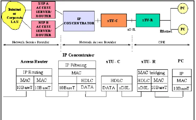
In a Layer 3 network, packet-based traffic is routed at the network layer of the OSI stack.
Figure 9 Elements in an IP xDSL Network
All traffic is routed as packets, based on IP addresses. It may be concentrated at the router. It is normally carried on dedicated pipes over IP or Frame Relay backbone.
3-2.1 IP Filtering
The IP concentrator may be configured in IP Filtering mode. In this mode the IP concentrator
transparently routes traffic based on IP addresses. This configuration allows users to remain connected to the network as if they were on a LAN, though with an extensive set of security features.
The IP Filtering network application is in fact an extension of the Internet. Hence the hierarchical structures used for scaling the Internet are applicable to the IP filtering xDSL network.
LAN architecture does not contribute to service selection. Its disadvantage is that it requires complete Layer 3 administration by the NAP. However, its advantage is that its the simplest and most easily understood network architecture among those that have been proposed.
System Overview
Figure 10 IP filtering
3-2.2 Virtual LAN
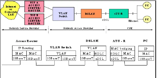
In order to eliminate “ Layer 3 ” management functionality from the NAP, a Virtual LAN (VLAN) may be used to utilize an existing MAC or ATM layer to the transit network.
The VLAN switch creates VLAN tagging used by the IP Concentrator for routing.
What makes VLAN attractive is the fact that the NAP is relieved from Layer 3 processing and IP address assignment. The association between the ATM VC or the Layer 2 Switch VLAN tagging and the xDSL port is algorithmically determined - requiring no configuration. This mapping is visible only on the internal interface between the IP Concentrator and the external box.
Two main ways to use the IP Concentrator VLAN functionality:
• Using an Ethernet switch
• Using an ATM switch.
3-2.2.1 Using an Ethernet switch
System Overview
Figure 11 VLAN tagging using Ethernet switch
3-2.2.2 Using the ATM Switch
Using an ATM layer 2 switch performs two tasks:
1. Extracts and inserts a MAC layer header that identifies a mapping between the xDSL link and the VPI/VCI
2. Performs RFC 1483 encapsulation of packets
System Overview
3-2.3 IP Tunneling
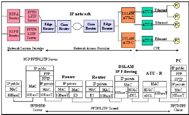
IP tunneling in the IP xDSL network works similarly to the way IP tunneling works on the PPP/ATM model, beside the fact that the PPTP/L2TP server is now across the operator’s IP backbone. The user receives service from two IP networks: The transport IP network, which connects users to service providers and which has its own IP address domain (privately administered by the operator); and from the overlay IP network, which is either the Internet (when connecting to an ISP) or a corporate Intranet (when connecting to a corporate access server).
In IP tunneling mode, the service provider has to place a PPTP/L2TP server on the front-end of his access point to the operator’s IP backbone.
When using Point-to-Point Tunneling Protocol (PPTP) or Layer 2 Tunneling Protocol (L2TP), the Layer 3-address administration is not removed from the Network Access Provider. However, NSP selection is accomplished without the intervention of the NAP.
The same PPP/IP tunneling paradigm can be applied to an IP-based xDSL network, where Ethernet remains in the subscriber LAN. The use of PPP as the user plane protocol makes the migration from today’s analog modem to IP xDSL transparent to the end user.
Figure 13 Layer 3 xDSL Network Architecture Using IP Tunneling (PPTP or L2TP)
Since IP Tunneling uses PPP in the user plane, all the attractive attributes remain:
• User authentication via PAP
• Data security (i.e. encryption) - supported in the protocol
• IP address assignment - supplied by the NSP
• DNS and gateway server assignment
• IP routing table - size and maintenance
• Multi-protocol support
With these advantages, PPP enables the subscriber to select Network Service Provider on a dynamic basis without the intervention of the NAP.
In addition, the subscriber continues to use his PPP “Dial-Up” networking paradigm the way he or she is familiar with from analog modems and ISDN terminal adapters.
System Overview
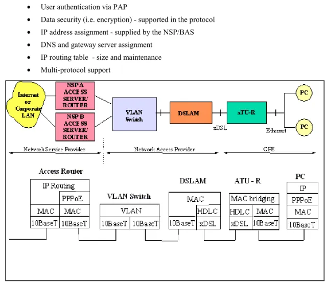
3-2.3.1 PPPoE
In order to support the PPP session used in the old analog modem as well as in the ATM model a new tunnel “alike” mechanism can be used.
The user creates the PPP session encapsulated in MAC frames. The NSP provides the PPPoE sever which is actually the BAS - Broad Band Access server. As described in the Tunneling case, the user uses PPP in the user plan so all the attractive attributes remain:
• User authentication via PAP
• Data security (i.e. encryption) - supported in the protocol
• IP address assignment - supplied by the NSP/BAS
• DNS and gateway server assignment
• IP routing table - size and maintenance
• Multi-protocol support
Figure 14 A Layer 2 xDSL Network Architecture Using PPPoE
With these advantages, PPP allows the subscriber to select Network Service Provider on a dynamic basis without the intervention of the NAP.
In addition, the subscriber continues to use a modified PPP “dial-up” networking paradigm the way he or she is familiar with from the analog modems and ISDN terminal adapters.
System Overview
4. IP POTS/Universal System Elements
This section provides specifications for FastInternet’s main building blocks.
4-1. Customer Premises Equipment (CPE)
CP Modem (ATU-R) CP Splitter
CP Microfilter CP Microfilter Figure 15 CPE
The ATU-R is a stand-alone unit that contains the xDSL modem and an Ethernet interface. An optional passive POTS/ISDN Splitter or microfilters may be installed according to the customer’s need. The CPE unit is AC-powered, though the POTS / ISDN signal is completely independent of power failures or any other failures of the modem unit.
4-1.1 POTS and Universal CPE Splitters
4-1.1.1 General
This module splits/combines the analog telephone signal and the modulated digital signal towards the twisted-pair line going to the CO. The splitter is a passive device, so the POTS/ISDN continues to function normally even when there is a power failure or any other fault in the xDSL Modem. The Splitter is a separate box, installed at the home boundary. It is required in installations where POTS is used along with FastInternet data access over the same copper line.
The Splitter Unit connects at the network side to the twisted wire coming from the CO and at the customer premises (CPE) side to the POTS/ISDN wiring and to the Modem/Bridge unit.
There is practically no cross-interference between the POTS/ISDN signals and the xDSL data channel and there are absolutely no limitations on simultaneous use of the two services.
System Overview
4-1.2 Interfaces
The Splitter has 3 interfaces:
1. Network/POTS interface: The POTS Splitter features an 8 pin RJ-45 jack. Pins 1,8 (the outermost pins) carry tip and ring to the in-house POTS distribution wiring. Pins 4,5 (the innermost pins) carry tip and ring from the network interface.
2. Telephone interface: 2 wires, RJ-11 3. Modem Line Interface: 2 wires, RJ-45
4-1.3 Physical/Environmental
• Weight: 0.3 Kg
• Power: None (fully passive unit)
• LPF 16 kHz (POTS + Billing Tone+ ISDN 2B1Q +ISDN 4B3T)
• Operating Temperature Range: 0 to 50°C
•••• Non-Operating Temperature Range: -40 to 70°C
•••• Relative Humidity: 5% to 95% Non Condensed
•••• Standard compliant: CE mark (EN 60950,EN55022,K21), UL 1950, FCC15 Class B
• Dimensions: 32mm H x 98mm W x 145mm L
4-1.4 Micro Filter
4-1.4.1 General
To avoid the need for central splitter installation at the customer premises, to save the cost of a “truck-roll” and to solve the problem of one xDSL point or the need for rewiring, Orckit Communications offers a second solution based on Micro-Filters for implementation with both G.Lite and full ADSL. The Micro-Filter is installed between the telephone and the wall jack. The customer can install it. Its performance parameters are identical to those of the centralized splitter.
Micro-filters used in deployed FastInternet systems include Wall mount and In-line configurations from
various vendors: YCL , Excelcius, Siecore.
4-1.5 ADSL CPE Modem
4-1.5.1 General
The ADSL CPE Modem modulates data transmitted by the customer and demodulates data streaming towards him/her. Asymmetrical data rates of up to 8 Mbps downstream and up to 768 Kbps upstream are transmitted along with analog POTS/ISDN signals over standard telephone lines.
4-1.5.2 Transmission
• DSL Modem Line Code: DMT
• Full-Rate ADSL and ADSL Lite Functionality
• Standards Supported: ANSI T1.413 Issue 2 category II, ITU-T G.992.1 and ITU-T G.992.2
• Error Correction: Reed-Solomon block code and Trellis Coded Modulation
System Overview
• ADSL chip: Orckit-FML KeyWave¥
• Data Rates: Asymmetrical. Downstream rates up to 8.192 Mbps and upstream rates of up to 768Kbps, with 32 Kbps resolution.
• Automatic data rate adaptation: The CPE and CO modems will negotiate, in the startup process, the highest data rate possible for the specific line and noise conditions. Limitations on the possible data rates will be software configurable.
• Automatic operation mode: The CPE and CO modems negotiate using the G.994.1 (Handshake) standard protocol to choose operation mode (Full Rate Lite or Issue 2 ADSL)
• Loop reach and noise requirements: In accordance with ANSI T1.413 Issue2 category II, ETSI ETR 328 and ITU-T G.996.1.
• Bit Error Rate: 1E-7 or better.
4-1.5.3 Management
• Remote DSL Management, Monitoring and Control: Maintained using the CO modem management tools.
4-1.5.4 Interfaces
• Telephone Line Interface: 2-Wire, RJ-11 (interface to CPE Splitter or Wall jack)
• 10BaseT Ethernet with RJ45 LAN / PC Interfaces is available
4-1.5.5 Physical/Environmental
• Plastic cover: stand-alone or wall mounted box.
• Dimensions: 165mm (W) × 225mm (D) × 45mm (H)
• Weight: 0.6Kg
• Input Power: 90-240 VAC, 50-60Hz
• Power Dissipation: lower than 6W.
• Operating Temperature Range: 0 to 50°C
• Non-Operating Temperature Range: -40 to 70°C
4-1.5.6 Integrated Bridge Functionality
4-1.5.6.1 General
The Bridge is integrated with the xDSL Modem as part of the stand-alone CPE. It implements Layer 2 functionalities necessary to achieve end-to-end data connectivity for Internet access or other data applications. User MAC packets with a destination outside the user’s LAN are encapsulated in HDLC frames and transmitted over the twisted pair by the xDSL modem.
System Overview
4-1.5.6.2 Bridge Specifications
• UTP LAN interface
• 10 Mbps in half-duplex mode or optional 20 Mbps in full-duplex mode
• Automatic TP polarity reversal
• 10,000 MAC address table
• Buffer: 256 packets
• Filtering: 15000 pps
• Forwarding: 15000 pps
• Latency: 1 packet
• Automatic LAN MAC address learning and aging
System Overview
4-2. Central Office (CO) Equipment
Central Office equipment includes two main components: the DSLAM Shelf and the CO Splitter Shelf. The CO shelf version is intended for installation in 19” racks and 600 mm ETSI racks. Another CO shelf, with extended slots, can be installed on 23” ANSI racks.
The shelf version consists of a DSLAM shelf and a CO splitter shelf. Figure 16 shows Orckit’s DSLAM shelf (IP Concentrator-based), Figure 17 shows Orckit’s DSLAM shelf (Bridge Card-based) and Figure 18 shows Orckit’s CO splitter shelf.
Figure 16 DSLAM Shelf with IP Concentrator Figure 17 DSLAM Shelf with Bridge Card
Figure 18 CO Splitter Shelf
4-2.1 Splitter Shelf
4-2.1.1 General
Orckit’s CO Splitter shelf is a 12-slot shelf supporting up to 96 POTS or ISDN lines. Each CO splitter card is fully passive. The splitter contains eight independent splitter circuits. CO splitter cards are used to separate the ADSL signals from the narrow-band POTS or ISDN signals.
The Splitter shelf can be located at the CO’s MDF with easy access to the subscriber loop pairs. In this case, the DSLAM Shelf can be located in a different place within the CO, with cables connecting the DSLAM Shelf and the Splitter shelf. The DSLAM shelf connects to the Splitter shelf’s Common Connector Panel (CCP). The CO Splitter shelf is presented in Figure 18 above.
System Overview
4-2.1.2 Interfaces
The splitter shelf contains these connectors:
• LINE – 12 x D25 male connectors connected to the subscriber lines.
• XDSL – 12 x D25 male connectors connected to the xDSL modem shelf.
• POTS/ISDN - 6 x D37 male connectors connected to the PSTN switch.
4-2.1.3 Physical/Environmental
• Dimensions: 430 mm (W) × 271 mm (D) × 300 mm (H); 19” rack mountable
• Weight: 3 Kg empty shelf
• Input Power: None (fully passive unit)
4-2.2 Central Office (CO) Splitter Module
The splitter module contains eight POTS or ISDN Splitters, enabling provisioning of a POTS/ISDN service over the same twisted-pair. It is a fully passive plug-in module that fits into the Splitter shelf.
4-2.2.1 Interfaces
• Backplane connector: 6*4 2 mm connector.
4-2.2.2 Environmental
• Input Power: None (fully passive unit)
• Operating Temperature Range: -40 to 80°C
• Non-Operating Temperature Range: -50 to 100°C
• Storage Humidity: 5-95% relative humidity non-condensing
4-3. DSLAM Shelf and Modules
4-3.1 DSLAM Shelf
4-3.1.1 General
The DSLAM ETSI shelf is a universal shelf with 14 slots. It includes these cards:
• 12 ADSL line cards with 4 ADSL modems per card, supporting up to 48 ADSL links per shelf.
• 1 or 2 IP concentrator cards, aggregating all DSL traffic from the modems to the network backbone and vice-versa.
• 1 or 2 Bridge cards (as an alternative to the IP concentrators), providing point-to-point connections with guaranteed bandwidth.
• 1 SNMP Shelf Manager (SSM) card, providing management capability for up to 4 DSLAM shelves.
System Overview
DSLAM shelf management is performed directly via a RS-232 connection or through an SNMP agent that provides an interface to SNMP remote management stations (see Section 5). The DSLAM backplane features a star architecture.
4-3.1.2 Dimensions
Width: The DSL shelf can be mounted in a 19’’ rack or a 600mm ETSI rack.
4-3.1.3 Connectors
The DSLAM shelf has these connectors:
• POWER (-48V)
• SHELF ADDRESS - 4-position dip switch
• ALARM - Three DB-9F connectors
• LOOP - Two 50-pin amp champ connectors for interface to Splitter Shelf
• RS485 - Used for chaining up to four shelves managed by a single SSM card
• NMS - Interface to craft PC for shelf management
• ETHERNET - Four 10Base-T Ethernet RJ-45 connectors for interface to: Shelf Concentrator (only for IP systems), SSM and selected modem slots
• E3 - Four BNC-type connectors for interface to future E3 Shelf Concentrators
4-3.1.4 Power supply
Each card installed in the DSLAM Shelf has its own power supply. No support for a central power supply is required.
4-3.2 ADSL line card
4-3.2.1 General
The ADSL CO line card is a plug-in module that fits into the DSLAM shelf. It includes four ADSL modems. Traffic is transmitted asymmetrically: data rates are up to 8.192 Mbps (POTS) and up to 6.144 Mbps (UNI) downstream, and 768Kbps upstream. Each CO line card modem communicates with four CPE units installed at the customer ends.
4-3.2.2 Transmission
The transmission characteristics of CLC4 line card, both POTS and UNI, are the same as those of the CPE modem.
4-3.2.3 Management
Local xDSL Management, Monitoring and Control: Available through the SSM card.
4-3.2.4 Interfaces
System Overview
4-3.2.5 Physical/Environmental
• Input Power: Supplied through DSLAM shelf
• Power Dissipation: 20W (per 4 lines)
• Operating Temperature Range: 0 to 50°C
• Non-Operating Temperature Range: -40° to 70°C
4-3.3 IP Concentrator
The IP Concentrator card aggregates all xDSL link traffic into a single 10Base-T interface in two optional modes:
1. Under relatively low load conditions, a number of shelves can be concatenated, resulting in a single 10Base-T interface supporting a higher number of subscribers.
2. Under heavy load conditions, the additional interface can be configured for load sharing, resulting in two 10BaseT interfaces per shelf.
Up to two IP Concentrator cards can be installed in a single shelf, providing a total of 40 Mbps aggregated throughput.
MAC packets encapsulated in HDLC frames are transmitted/received on the xDSL links. The MAC packets are aggregated to the 10Base-T interfaces. The IP Concentrator card can work in either IP filtering or VLAN mode. In IP filtering mode, the IP Concentrator performs transparent IP routing, handles IP address management (both static and dynamic allocation schemes) and multicast IP
registration. In VLAN mode, the IP Concentrator performs a transparent forwarding of layer 2 packets, where each xDSL link is mapped to a unique VLAN, which can be further mapped by a rack to an Ethernet VLAN or an ATM VC. (See Section 3 for more details regarding these modes).
4-3.3.1 IP Concentrator Functionality
The IP Concentrator supports the following operating modes:
• Layer 3 service - IP filtering mode
• Layer 2 service - VLAN mode
4-3.3.1.1 Layer 3 Service Features
Layer 3 service is based on IP FILTERING and transparent routing performed by the IP Concentrator. The IP Concentrator performs and provides:
• IP address management
• IP filtering, in co-operation with the xTU-R internal MAC bridge
• Network security
• Multicasting
• Local switching option (usually blocked for security enhancement)
4-3.3.1.2 Layer 3 Service Address Management
• The IP Concentrator stores all IP address information (incl. subnet and subnet masks) allocated to DSLs
• Static addresses (up to 4 subnets per DSL) are defined by the NMS and remain in use until deleted
System Overview
• After assigned lease on an IP address expires, the IP Concentrator automatically removes it.
• Maximum number of dynamic addresses defined by management (up to 16 addressed per DSL)
4-3.3.1.3 Layer 3 Service IP Filtering
Handling of Upstream Packets
• Upstream packets sent by the xTU-R bridge to the IP Concentrator are discarded if not using a valid source IP address:
• Protects stations from being exposed to network
• Protects network from impersonation
Handling of Downstream Packets
• Downstream packets are discarded by the IP Concentrator if not using a valid destination IP address
• Valid packets are sent only to the DSL serving the destination, including broadcast packets (e.g. ARP)
• Stations connected to xTU-R are not visible to other xDSL users
4-3.3.1.4 Layer 3 Service - Multicasts
• Support for Local Subnet Multicasts
• Enabled/ disabled by NMS
• When enabled, multicasts are accepted only from user-defined subnets (1 per 10BaseT I/F)
• Support for IP Multicast
• IP Concentrator tracks IGMP packets
• IP Concentrator handles registration of xTU-R users in IP multicast groups
• Multicast IP packets are transmitted only to registered xTU-R users
4-3.3.1.5 Layer 3 Service – Local switching
• Permits connection between users through DSL ports
• Enabled/ disabled by NMS
• Usually disabled due to network security: upstream packets are always forwarded to the Ethernet port without querying the forwarding database.
4-3.3.1.6 Layer 2 - Service models (VLAN mode)
• Each customer is connected using an Ethernet VLAN or an ATM VC to an ISP. ATM VCs are translated to Ethernet VLANs and then to ADSL Links
• Virtual Connection is created between ISP and CPE.
• Telco is not involved with Layer 3 protocols.
System Overview
4-3.3.2 Network Ports Configuration
The two Ethernet Network ports, on each concentrator card, can be configured to operate in one of the two following modes:
• Daisy chain: multiple concentrators (or shelves) through a single ethernet port.
• Load sharing: the total traffic per shelf is distributed through the two ethernet ports. When two IP concentrators are installed in each shelf, FastInternet can be operated in one of the
following configurations:
• Daisy chain with distributed load: Multiple concentrators (or shelves) through two ethernet ports to the network backbone, while the traffic at each shelf level is distributed through the two IP concentrators cards, without redundancy.
• Quad connection Load sharing: The total traffic in a single shelf is distributed through the four available ethernet ports, providing 40 Mbps for 48 users, without redundancy.
• Redundant mode: Single shelf or multiple concatenated shelves through one ethernet port when one concentrator is online (active mode) and the second one is in stand-by mode.
4-3.3.2.1 Daisy Chain mode
In this mode only network port 1 connects to the network. Network port 2 is connected to Network port 1 of another IP concentrator installed in another DSLAM shelf (illustrated in Figure 19 below). All modems data, together with the information received through port 2, is forwarded through port 1. This mode is suitable for low traffic loads with limited latency requirements.
Figure 19 Shelf Concentrator daisy chaining
Daisy chaining shelf concentrators is performed in a store-and-forward manner: A full packet is first received on one interface of the IP concentrator, stored internally in its memory, and then transmitted on the other interface.
The two interfaces have no synchronized timing and need not have one.
Any received packet is first transmitted on the daisy-chained interface and then processed by the concentrator routing engine. This is done in order to minimize latency introduced by the daisy-chain configuration. To demonstrate this concept, assume that a packet is received from the backbone (see Figure 19) network, assigned to an xDSL line served by the lowermost shelf concentrator. The packet
System Overview
is received on interface 1 of the uppermost concentrator. It first transmits the packet to interface 2 and then puts it in an input queue. The packet is then pulled, at its turn, from the input queue and processed by the routing engine, which discovers that its destination is none of the xDSL lines served by the uppermost IP Concentrator and hence discards the packet. The same process is repeated on the middle concentrator. Only the lowermost IP Concentrator’s routing engine finds an appropriate destination for the packet and transmits it on the appropriate xDSL line.
Each backbone interface is polled for received packets each 70-100µS. This means that the latency introduced by each degree in the daisy chain is equal to 100µS plus the serialization time of the packet on the daisy-chained interface.
In the 10BaseT IP concentrator, the following options are possible for the logical daisy-chain operation:
• In static IP filtering mode, each IP Concentrator is assigned different IP addresses. The routing engine routes by the destination IP address of the packet and discards packets with destination address other than its assigned addresses.
• In dynamic IP filtering mode, each IP Concentrator learns the dynamic IP addresses allocated to xDSL lines served by it, and ignores the rest. The routing engine routes by the destination IP address of the packet and discards packets with a destination address not allocated to one of its lines.
• In VLAN mode, each xDSL line is associated with a unique VLAN ID, calculated according to the line’s physical location in the shelf and an offset assigned to the IP Concentrator. A VLAN ID can be further associated with an Ethernet VLAN or an ATM VCI. The routing engine routes according to the packet’s VLAN ID and discards packets with a VLAN other than its assigned VLAN IDs, determined by the assigned offset.
4-3.3.2.2 Load Sharing mode
In this mode, the IP concentrator accepts traffic through both network interfaces. Each xDSL line in the shelf is mapped to a specific backbone interface, thereby distributing the traffic between the two interfaces for a single concentrator configuration or between the four interfaces for a dual-concentrator configuration (illustrated in Figure 20 below). This mode is suitable for high traffic load conditions.
Figure 20 Shelf Concentrator Load Sharing
Mapping xDSL lines to the backbone interface is static because two backbone interfaces (or sub-interfaces) will be typically connected to two interfaces of a service provider’s router, and hence will be assigned IP addresses from two distinct subnets. (This is the case even if the clients are dynamically assigned IP addresses via DHCP). A standard for dynamic load sharing does not exist and some vendors are using proprietary mechanisms to interconnect their own equipment.
System Overview
4-3.3.2.3 Redundancy mode
Two IP Concentrators can serve a single shelf in two modes: Load sharing mode or redundancy mode. In redundancy mode, one IP Concentrator is online and actively serves all the xDSL lines in the shelf, and the other is in “standby”. It receives all packets and updates its IP address database based on DHCP transactions. When the network management system finds that the online IP Concentrator failed, it switches the standby IP Concentrator to online, and that IP Concentrator immediately takes control over the shelf.
The two backbone interfaces of the redundant IP Concentrators should be connected to the same service provider’s router interface using an Ethernet hub \ switch.
It’s possible to jointly use daisy chain and redundancy. In this case two redundant chains are connected at their root to a single service provider’s router interface (see Figure 21). If one IP Concentrator in one of the chains fails, the network management system switches all IP Concentrators in the failed chain to standby, and all IP Concentrators in the redundant chain to online.
Figure 21 Joint Daisy Chain and Redundancy
It’s also possible to jointly use load sharing and redundancy. In this case, two load-shared interfaces are connected via a switch to a single service provider’s router interface. Under normal operation, traffic is split between the two interfaces. If one of the IP Concentrators fails, the network management system maps all xDSL lines previously served by the failed IP Concentrator to the operating one.
4-3.3.3 Network Planning Considerations
This section discusses the considerations that need to be taken into account when planning the network. The main issue is daisy chaining (with how many IP Concentrators chained) versus load sharing. Two important considerations: Bandwidth and Delay. Generally, only throughput is of interest, though both bandwidth and delay impact on the available throughput.
System Overview
Bandwidth considerations
The backbone interface bandwidth is divided between all xDSL lines served by that connection. Using the 10BaseT, the backbone interface should be connected to either an Ethernet switch port or to a router port. In both cases, there are effectively no collisions on the Ethernet segment, and assuming client-server internet applications, the 10 Mbps bandwidth is split between downstream and upstream at a ratio of 576:64 (typical TCP data / acknowledgement packet size ratio), resulting in a 9 Mbps bandwidth for the downstream.
Various analyses and studies indicate that among all users are in an active session, a concentration ratio of 9:1 can be used to assure 99% probability that a user gets a throughput of more than 50% of his link rate. And a concentration ratio of 18:1 can be used for a probability of 95% to get the same throughput assurance. The models assume WEB browsing applications and do not reflect possible broadband applications such as video over IP, which has different characteristics.
In the dial-up world, service providers take an additional factor 0f 10:1-8:1 as their model of the ratio between active residential users and the total amount of users in peak hour. This is the factor used to dimension the service providers’ dial-up modem pool. This criterion doesn’t hold for business customers, assumed to be always active during business hours.
Therefore, for residential users a concentration ratio of 1:10 - 1:100 can be used, depending on the application and the type of users. For example, assuming 1.5 Mbps ADSL lines concentrated into 10BaseT interface and a concentration ratio of 1:8 gives 48 xDSL lines.
Delay considerations
The delay introduced by the DSLAM can be delineated into three:
1. The daisy-chaining delay, which is 100µs, for each degree, plus the serialization time of the packet on the daisy-chained interface. For 576 bytes downstream and 64 bytes upstream packets, the total daisy-chaining contribution to the round-trip delay is 0.5 ms for the 10BaseT IP Concentrator.
2. The queuing caused by the processing time of the routing engine in the IP Concentrator. The total time dedicated to processing a packet in the IP Concentrator, including all
overhead such as the relative time dedicated to management, is 70-100µs. Assuming a shelf of 48 lines with a model where 10% of the lines are involved at some point of time in the transmission of one downstream and one upstream packet, this will cause the polling cycle of a packet to be about 1 ms, and the average delay introduces by the queue will be 0.5 ms. 3. The serialization time of the packet over the xDSL line. For ADSL, this delay is mainly
contributed by the interleaving delay. In the maximum interleaving depth option, the round-trip delay contribution of the xDSL line is 38 ms, which makes all other contributions to the delay negligible.
The worst-case scenario of a round-trip delay can be solved by configuring a large enough receive TCP window in the xDSL user’s PC to eliminate the influence of the delay introduced by the DSLAM on the achievable throughput.
System Overview
4-3.3.4 IP Concentrator Performance
4-3.3.4.1 Packet Delay
The time to process a packet, measured from when the last bit in the packet is received to the time the first bit in the packet is ready to be transmitted (assuming the forwarded port link is free), does not exceed 2 milliseconds (ms).
4-3.3.4.2 Packet Throughput
The IP concentrator is capable of forwarding a total 10,000 PACKETS per second (pps). This is equal to full-wire speed at both Ethernet ports with 500-byte-long packets, which are normal length packets in Internet access.
4-3.3.4.3 Packet Buffering
The IP concentrator buffers 50 Kbytes of data for each port in its transmission queue for the longest packet length (1500 bytes). The IP concentrator has 4Mbytes of shared buffer memory.
The source of this requirement is the TCP windowing process. TCP protocol can transmit a “window” (a certain amount of bytes) before receiving an acknowledgment. With high-speed links, the window size should be maximized so that the propagation delay of the acknowledgment packet will not limit the connection bandwidth, and the link speed will be the limitation. 50Kbytes are enough for up to 8Mbps links. Moreover, in large file transmissions, the largest packets are usually used to avoid overheads.
4-3.3.5 Interfaces
• 2 x 10 BaseT Network interface ports on RJ45 connectors (100 BT available on Q2/2001)
• RS-232 interface for local Management
4-3.3.6 Physical/Environmental
• Input Power: Supplied through DSL shelf
• Power Dissipation: 5W
• Operating Temperature Range: 0 to 50°C
• Non-Operating Temperature Range: -40 to 70°C
4-3.4 Bridge card
4-3.4.1 General
The Bridge Card provides Telcoms with a non-concentrated, point-to-point solution for the CLC4 and the capability of a non-blocking bandwidth capacity of up to 10 Mbps, half or full duplex, per line/port. Each bridge card supports up to 24 ADSL lines in the ETSI shelf through 24 10 BaseT interfaces. The Bridge card can be inserted in the same slots as the IP concentrator to support both the left side and the right side of the shelf. The Bridge card features 12 Shielded RJ45 Female connectors. Each RJ45 connector supports 2 links.
System Overview
Two Bridge cards can be installed in a single shelf to support a fully loaded shelf (without SSM card) with 12 CLC4 cards / 48 ADSL lines, with a total bandwidth capacity of 480 Mbps.
The Bridge card does not run any software and does not have any management interface except from informing/reporting mechanism implemented by the hardware.
4-3.4.2 Bridge Card Functions
The Bridge card features the following functions:
• When inserted into slots 7 or 8 in the ETSI shelf, the Bridge card automatically configures itself to support the relevant links.
• Link support: The Bridge card placed in slot 7 supports slots 1 to 6; the Bridge card placed in slot 8 supports slots 9 to 14.
• Bridge card features an assembly option supporting Half/Full duplex traffic.
• Bridge card features an assembly option supporting/not supporting bridge filtering.
• Bridge card features an assembly option supporting/not supporting staffing.
4-3.4.3 Bridge Card Performance
The entire subrack correctly transmits IP packets:
• At different ADSL rates.
• Interleave and Fast.
• Adaptive and Fixed Rates
• Following recovery after disruption
Disruptions include:
• Disconnecting the ADSL line.
• Turning off the ATU_R3.
• Plugging the CLC4 out of the subrack.
• Plugging the bridge card out of the subrack.
• Disconnecting the Ethernet connector from the bridge card.
• Disconnecting the Ethernet connector from the ATU-R3.
• Turning off the subrack’s power supply.
While transmitting data, the following telephony operations are performed:
• Repetitive on/off hook.
• Ringing.
• Ring trip.
• Dialing.
The Bridge card transmits the wave shape of the Ethernet outputs according to IEEE 802.3 requirements. The Bridge card does not affect the rate reach of links.
System Overview
4-3.4.4 Interfaces
• 12 multi-RJ45 front-panel connectors/ports supporting 24 10BaseT bridges.
4-3.4.5 Physical/Environmental
• Input Power: Supplied through DSL shelf
• Power Dissipation: 25W
• Operating Temperature Range: 5 to 45°C
• Non-Operating Temperature Range: -40 to 70°C
System Overview
5. Network Management
5-1. General
FastInternet can be managed through two main management systems:
OrViewTM Direct - a PC based windows graphic management application software system enabling simultaneous management of up to four independent DSLAM shelves, through local RS232 serial interface or remote (via modem link) connection. The management software automatically identifies the hardware installed in each shelf and enables the user to separately manage each link up to the maximum capacity of a DSLAM shelf , eg 48 x 4 (192) ADSL links.
OrViewTM Plus - an SNMP (Simple Network Management Protocol) application, running on multiple
Unix/Solaris platform for the main server and on PC Windows NT for graphical operator interfaces. This application can manage and monitor the objects of the FastInternet system, from one central management station connected through a WAN to several DSLAMs distributed across multiple sites, using in band and/or out of band interfaces.
Based on the Telecommunications Management Networking (TMN) concepts of the ITU-T, the OrView Plus SNMP application supports such open standards as CORBARN and therefore can be
seamlessly connected to any external Service Management Systems such as billing, ordering and CRM systems.
These two applications interface with the shelf embedded SNMP Shelf Manager (SSM) card in order to manage each individual DSLAM, using different protocols:
Back Plan Protocol (BPP) proprietary protocol for OrView Direct and SNMP protocol for OrView Plus.
In addition the SNMP interface, based on standard as well as Orckit defined MIBs (Management Information Models), enables FastInternet management through any third party SNMP based system. DSLAM network management in its entirety is illustrated in Figure 22.
System Overview
Figure 22 DSLAM Network Management System
5-2. OrView™ Direct Management
Management functions available to the user include:
• System configuration functions (including downloading of new software releases and configuration files).
• System diagnostic functions (display of performance diagnostics, display of logistic data, and initiation of test activities).
• System control functions (resetting and disabling of systems not in use).
• System housekeeping functions (passwords, selection of configuration options, access to help system, display of system hardware and software versions, display of Orckit contact information).
OrView Direct management software uses the standard Windows man-machine interface, and therefore all the basic operations comply with Windows standards. A typical window, Slot Map, showing the status of each card/slot in the connected DSLAM, is displayed in Figure 23.
System Overview
Figure 23 OrView™ Direct Slot Map
5-3. OrView™ Plus SNMP Network Management
5-3.1 SNMP Shelf Manager
5-3.1.1 General
The SNMP Shelf Manager (SSM) card includes an SNMP agent enabling multiple local and/or remote SNMP managers to control multiple shelves via a single managed entity.The SSM manages all elements physically located in multiple connected FastInternet shelves including their xDSL line cards, IP
Concentrators. In addition, the SSM manages all xTU-Rs connected via the xDSL line cards. Each SNMP Manager can manage multiple SSMs in parallel. Each SSM card can manage up to 4
FastInternet shelves each containing up to 48 xDSL links. The SSM is a plug-in card of the DSLAM
shelf.
The SNMP Manager communicates with management cards (SSMs) that are plugged in the remote
FastInternet shelves. The SSM functions as a mediator device between the FastInternet elements and
the management system. Commands from the SNMP Manager are passed to the SSM that translates and directs them through an RS-485 bus implemented in the DSLAM shelf backplane and between shelves to the required managed element. In the other direction, the response from the element is delivered via the SSM to the SNMP manager. Besides receiving commands from the manager, the SSM polls in a “round-robin” each of the elements, monitors their status and sends, when needed, an alarm to the manager.
The SSM supports the SNMP protocol. It includes an SNMP agent complying with RFC 1155. The agent exports an internal MIB implemented partially in the SSM and partially in the managed elements (In general, history is kept in the SSM and current values are always imported from the element on SNMP command).
System Overview
5-3.1.2 Supported MIBs
Supported MIBs include:
• ADSL MIB according to the current draft of the ADSL Forum
• MIB II (RFC-1213)
• Orckit defined IP Concentrator MIB
5-3.1.3 Element Management
The protocol used between the SSM and its elements is a simple command-response protocol. Each managed element has a unique address allowing the SSM to address when required. The xTU-Rs are managed via the Embedded Operation Channel – EOC of the xDSL modem and have a unique element address.
Using the commands protocol, the SSM can configure each element, get its status, diagnostics, get performance statistics, activate Loopback or reset the module. The SSM addresses the elements in two cases:
• The SSM responds to an SNMP command.
• The SSM polls the element in a Round-robin fashion.
5-3.1.4 Hot insertion capabilities
Hot insertion of the cards is supported. The SSM will automatically identify extraction and insertion of xDSL line-cards in the shelf and will alarm the connected SNMP managers.
Hot insertion of the SSM itself is also supported; hence extraction and insertion of SSM card will not affect or degrade the operation of the other modules in the sub-rack.
The SSM will include non-volatile memory, in order to avoid data loss in case of power failure. The protected database will consists of data accumulated in the last week, with 15 minutes increments.
5-3.1.5 Alarms dry contacts
The SSM supports Alarms via a separate dry-contacts. It is also able to read the status of other sub-racks Minor and Major dry-contacts alarms.
5-3.1.6 Software Download to Network Elements
The SSM supports software download to all ADSL links as well as software download to the
concentrator and SSM . This feature allows for the NMS to specify which elements should be updated with which software.
5-3.1.7 Physical/Environmental
The SSM is a temperature hardened component, as developed with industrial parts, that allow it to withstand temperatures from –40 to 85C.
System Overview
5-3.2 OrView
TMPlus SNMP Manager
5-3.2.1 General
OrView Plus is an efficient and scalable system combining fault management, configuration
management, interfaces for accounting management, performance monitoring and security management (FCAPS).
OrView Plus consists of one central Operations Supporting (OS) module and one or several Mediation Device modules (MDs), which communicate with the SNMP proxy agents in the DSLAMs (see Figure 22 DSLAM Network Management System). For the convenience of OrView Plus operators, there are user-friendly graphical consoles based on Java technology. Thus, the same system can support multiple users by adding more workstations and can scale up to support hundreds of DSLAMs simply by adding more MDs and more computing power.
Orview Plus SNMP Manager is used to manage and monitor xDSL links that are distributed across several sites. The manager software collects data from the network using SNMP (Simple Network Management Protocol).
The sites containing the FastInternet shelves are connected to the management station, through the
WAN via an Out of Band Ethernet connection at each IP DSLAM and In-Band DS1 connection at each FR DSLAM.
OrView Plus runs on widely used computing platforms. Both the OS and MD types of modules run on Sun UNIX£ computers. The graphical operator interface software runs on NT based PCs, and will be supported on additional platforms, including Web browsers.
The software uses a database for the storage of the system topology, equipment configuration and alarm and performance history logs.
5-3.2.2 Standard Reference
OrView Plus was developed in accord with widely used management standards such as the ETSI, ITU-T and OMG standards. Some standards supported are:
•••• ITU M.3010 standard (Principles for TMN)
• ITU M.3100 standard (Generic Network Information Model)
• ETSI EG 201 024 standard (User interface design principles for the TMN)
• ITU X.721 standard (Structure of management information: Definition of management information)
• ITU X.733 standard (Alarm reporting function)
• ITU G.992.1 G.DMT Standard (ADSL Transceivers)
• ITU G.992.2 G.lite (Splitterless ADSL Transceivers)
• ITU G.994.1 G.HS Standard (Handshake procedure for DSL Transceivers).
5-3.2.3 Main Functionality
OrView Plus offers telecommunication access providers a valuable strategic advantage in service quality and protection from equipment failures. Additionally, rapid service provisioning and activation ensure customer satisfaction. Reporting capabilities enable network engineers to analyze the network’s performance, to get statistics and to initiate preventative maintenance.
System Overview
OrView Plus’s main features are:
Fault management
• Real-time display of active alarms and their details
• Permanent summary of the alarms with audible new alarms
• Alarm acknowledgement by different users
• Alarm filtering and sorting
Configuration management
• ADSL configuration
• Configuration profiles definition and assignment
• Software download
Accounting and Performance management
• Performances Monitoring
• Threshold crossing alerts
• Interfaces to accounting related data
Diagnostics
• Continuity Checks
•
BER tests of ADSL linksSecurity and user management
• Users configuration management
• Log in/out
• Password modification
User configurable reports
• Historical reports for analysis
• Application specific or ad-hoc
• Graphical and textual display
•
Export of report data5-3.2.4 Modular Architecture
OrView Plus’s modular architecture allows for high scalability of the system. This system can support from a few to hundreds of DSLAMs. With its external CORBARN interface, OrView Plus is a real open
system - compliant with TMN standards – which can be interfaced easily with other network and service management systems (see Figure 24).
OrView Plus consists of 3 levels according to the TMN model: Mediation Devices (MDs) layer, Operations System (OS) layer and WorkStation (WS) layer for the operator interface with the system. The following is a general description of these three layers.
System Overview
Figure 24 OrView Plus Architecture
1. Mediation Devices (MDs) Layer. This layer learns and monitors the actual DSL
equipment. Each MD continuously polls the DSLAMs it manages and also gets alerts from them on faulty conditions. The MDs notify the OS as to any relevant alarm and
configuration change. MDs communicate with the network elements (the DSLAMs) through SNMP channels. Each MD can manage thousands of ADSL links (the exact number is in accordance with the computing power of the MD’s hardware). The MD is a UNIX£ process. 2. Operations System (OS) Layer. This layer is a consolidator of the comprehensive
management data for the whole access network. The OS communicates with the MDs and WSs and provides an interface to external systems through CORBARN channels. The OS
supports multiple MDs and multiple users (WSs). Among its tasks, the OS also enables the allocation of MDs resources among DSLAMs, and the system administration functions including central storage and backup/restoration. Additionally, the OS includes the central alarm manager process and the alarm correlation mechanism. The OS also manages the allocation of logical regions and sites, since it has the picture of the whole network. The OS is a UNIX£ process.
3. Workstations (WS) Layer. This layer enables the operators to access the data via a friendly and intuitive graphical user interface. The WS exchanges data with the OS and the MDs through the CORBARN interface. The CORBARN interface allows the operator to have
a transparent dialog between the different parts. The WS is based on Java technology. The user interface of the WS is compliant with the ETSI EG 201 024 standard.
System Overview
Due to its modular design, OrView Plus can be scaled up from a small system to a very large one. The following two examples demonstrate this:
Example 1. A small accesses network, with 5,000 ADSL links. A single Sun UNIX£ computer is needed for both the OS process and a single MD process. A single WS suffices.
Example 2. A larger network with few tens of thousands of links. OrView Plus may be combined into a distributed system with one OS and several MDs running on several UNIX£ servers. Few NT-based PCs will provide the operator interfaces with the system.
5-3.2.5 Graphical User Interface
OrView Plus features an intuitive graphical user interface (GUI) based on Java technology. The GUI has a consistent structure, combining the following parts: The Navigation Tree Area, the Graphical Work Area, Alarm Area and the Toolbar (see Figure 25 below).
System Overview
Appendix A Specifications: CO Units
DSLAM - Line card shelf
• 14 slot ETSI DSL Shelf: 425 x 260 x 444 (ETSI front mounting or 19" front mounting)
• POWER: 36 to 76 VDC (110 - 230V AC may supported as well)
• SHELF ADDRESS: 4-position dip switch
• ALARM: Three DB-9F connectors
• LOOP: Four 50-pin amp champ connectors for interface to Splitter Shelf
• NMS: Interface to craft PC for shelf management
• ETHERNET: 4 x 10Base-T Ethernet, RJ-45 connectors for interface to
• Shelf Concentrator, SSM (IP/FR versions) and select modem slots
• E3: Four BNC-type connectors for interface to future E3 Shelf Concentrators
ADSL Line Card
• Currently 4 modems/lines per card
• Support of:
• G.DMT (ITU-T G.992.1 , Annex A-POTS and Annex B-ISDN)
• G.Lite (ITU-T G.992.2 Annex A)
• T1.413 Issue 2, ETR328
••••
T1.413 Issue 1 category IIIP Concentrator Card
• Two (2) 10 Base-T half/full duplex interface ports
• Up to two cards per shelf supporting 40 Mbps aggregated-load shared traffic
• VLAN tagging support – according to IEEE 802.1q
• IP filtering support
• IP Multicast support – IGMP v1 & v2
• Statistical counters
• RS-232 interface for local Management
• Embedded management through the Ethernet ports
• Visual LED status indicators Applications
Bridge Card (Point to Point Network connection)
• 24 10Base-T interfaces per card
• Full Ethernet throughput support (IEEE 802.3).
System Overview
SNMP Shelf Manager Card (for use with IP/FR Concentrators)
• Supports MIB-II according RFC-1213
• Supports connection up to 3 SNMP managers via out-of-band (Ethernet on RJ45 connector) or via in-band.
•
Supports a local, remote or dial-in manager in parallel to SNMP management via RS232 connector.Splitter Line Card
• 8 splitters per shelf
• Optional LPF cut-off at 4 Khz (POTS), 16 Khz (POTS + Billing Tone) or
• 90 Khz (POTS + Billing Tone + ISDN 2B1Q + ISDN 4B3T)
• Passive Unit
Splitter shelf
• 12 slot ETSI Splitter Shelf: 425 x 260 x 444 (ETSI front mounting or 19" front mounting)
• LINE: 12 D type connectors connected to the subscriber lines.
• XDSL: 12 D type connectors connected - to the xDSL modem shelf.
• POTS: 6 D type connectors connected to the POTS switch.
Environmental
• Operating Temperature: -40 to + 65 C ambient
• Storage Humidity: 5 to 95% relative humidity non-condensing
• ETSI shelf standard compliant: ETS300 386-2, CE mark (EN60950, EN55022,20), FCC class A