Review
Invited
Pre-MRI Procedure Screening: Recommendations
and Safety Considerations for Biomedical Implants
and Devices
Anne M. Sawyer-Glover, RT(R)(MR)
1*
and Frank G. Shellock,PhD
2 Maintaining a safe MR environment is a daily challenge forMR healthcare workers, especially in consideration of the increasing number of clinical MR applications and the large and growing variety of biomedical implants and de-vices that are currently used in patients. This review arti-cle presents policies and procedures that should be used to screen all patients and individuals before allowing them to enter the magnetic resonance (MR) environment. Informa-tion pertaining to MR safety and the relative risk factors for implants, devices and materials is discussed. A comprehen-sive pre-MRI procedure screening form that is recommended for use by MR facilities is also included. J. Magn. Reson. Imaging 2000;12:92–106. © 2000 Wiley-Liss, Inc.
Index terms:Magnetic Resonance Imaging; safety; screening; bioeffects; implants
MAINTAINING A SAFE MR environment is a daily chal-lenge for technologists, radiologists, physicians, nurses, scientists, and allied health professionals worldwide. The types of biomedical implants and de-vices encountered in patients and individuals who must enter the MR environment continue to grow (1– 83). To provide the safest environment possible, con-stant attention and diligence are required to obtain current information and documentation about these objects. A particular challenge is to determine whether published testing procedures are thorough and compe-tent as well as how the results should be applied to manage patients in the MR facility. Establishing an effective pre-MRI procedure screening policy is the first critical component of a program guarding the safety of all individuals whot enter the MR environment. A sec-ond critical aspect is understanding what the relative risk factors are for the various biomedical implants and devices. In this review paper, the MR safety and
com-patibility for a variety of biomedical implants and de-vices will be discussed following the section on recom-mendations for pre-MRI procedure screening.
For implants and devices, it is important to evaluate objects with respect to “safety,” ie, the potential for injury of the individual or patient, and “compatibility,” ie, the potential for damage to the device and its asso-ciated components, the function of the device that will be affected during the MR procedure, and/or the poten-tial source of image artifacts. (Note that image artifacts will not be addressed in this article). With regard to “safety” and “compatibility,” the potential sources of concerns can be related to one or more of the fields present in the MR environment, that is, the static mag-netic field, the RF (radiofrequency) electromagmag-netic fields, and the gradient (time-varying) magnetic fields.
The issues regarding the interaction of a device and the static magnetic field of an MR system include at-traction or deflection, and torque. Potentially danger-ous magnetic field interactions can occur when ferro-magnetic materials are exposed to the static ferro-magnetic field. Characteristics ranging from significant projectile motion to modifications in the orientation of the device can be exhibited. This can result in injuries to the pa-tient or individual and/or MR facility personnel and physicians as well as damage to the device.
Interaction with the RF electromagnetic fields can result in heating of the device, its associated compo-nents (eg, lead wires), and/or surrounding tissues (eg, burns). This can occur when the anatomical area that contains the device and its associated components is exposed to the fields from the transmitting RF coil. In addition, imaging sequences that utilize multiple 180° RF pulses [eg, turbo spin echo (TSE), fast spin echo (FSE), etc.] are of greater concern than those with one 180° RF pulse [conventional spin echo (SE)], or none (gradient-echo acquisitions). These 180° RF pulses may produce high levels of RF energy deposition in the body, resulting in an increased specific absorption rate (SAR; measured in Watts per kilogram).
Also, as field strength of the MR system increases, the RF power deposited in the body increases. For example, the SAR for an individual at 1.5 T will be approximately nine times that for a comparable sequence at 0.5 T. The
1
Radiological Sciences Laboratory, Richard M. Lucas Center for MRS/I, Department of Radiology, Stanford University School of Medicine, Stan-ford, California 94305.
2
School of Medicine, University of Southern California, Los Angeles, California 90045.
*Address reprint requests to: A.M.S.-G., Radiological Sciences Labora-tory, Richard M. Lucas Center for MRS/I, Department of Radiology, Mail Code 5488, Room P273, 1201 Welch Road, Stanford, CA 94305. E-mail [email protected]
Received November 23, 1999; Accepted March 28, 2000.
potential for heating is a result of the RF fields being concentrated or focused in the area of the device and/or components due to the metal (ie, acting like an anten-na). The RF fields can also induce currents in a device or cable (eg, cables associated with surface coils, car-diac gating, and peripheral gating) that forms a loop with it or with the body of the patient.
Most MR system manufacturers and vendors of MR accessories and monitoring equipment now employ fi-beroptic or high-resistance cables to reduce the poten-tial for induced currents and patient burns. Many bio-medical implants utilize lead wires that are insulated. However, the end of the lead embedded in tissue, bone, or the spinal canal may not be insulated, or the lead may be broken, resulting in exposure of an uninsulated area. Thus, it is necessary for MR healthcare workers to be aware of the SAR associated with each scan on each patient to ascertain a possible hazardous condition. Notably, most MR systems provide this information.
The safety concern for gradient magnetic fields is related to the size (amplitude) and rapidity (slew rate) of the time-varying fields, which become stronger moving away from isocenter in all directions toward the periph-ery of the bore. This is especially an issue for MR sys-tems that utilize stronger gradient syssys-tems (both slew rate and amplitude) and rapid imaging sequences [eg, echoplanar imaging (EPI)]. Examples of these are in the range of 120 –150 mT/m/sec for slew rate and 20 – 40 mT/m (2– 4 Gauss/cm) for amplitude.
Similar to RF fields, a scenario associated with gra-dient magnetic fields can result in heating of the device, associated components, and surrounding tissue (ie, pa-tient burns), especially if a loop is formed between the cable and the body, or if the lead wire implanted in the body forms a loop. Again, it is important for MR health-care workers to know values for dB/dt (change in mag-netic field over time measured in Tesla per second) for each scan on each patient. This may be required to determine safety for a specific implant or device with a particular MR system and scan protocols. If the MR system does not provide this for each scan, documen-tation should be obtained from the manufacturer that provides this information, especially for scans involving worst-case or extreme scenarios.
The MR safety and compatibility of a magnetically or electrically activated implant with the static and elec-tromagnetic fields of the MR system must be considered prior to the MRI procedure. Magnets may be incorpo-rated into implants or devices to hold the implant in place, activate the implant, guide an external compo-nent to change the operation of the implant, or program the device (1).
Exposure to static magnetic fields of MR systems may perturb the function of the magnetically activated im-plants and/or demagnetize or displace the imim-plants. MRI procedures, therefore, should not be performed in patients with magnetically activated implants, or the implants should be removed from the patient before entering the magnet room (1– 4). Approval from the re-ferring physician should be obtained prior to removal of any biomedical implant or device. In addition to the prevention of patient injury, it must be ensured that the device will retain full and appropriate operation after
the completion of the MR examination. A liability may be created for the MR facility if the implant or device ceases to operate or function accurately as a result of exposure to the MR procedure.
Currently, the individual or patient may have a device identification and information cards that includes vital information about certain devices implanted in their body such as manufacturer, type, model number, serial number, composition of materials contained in the de-vice, and recommended policies by the manufacturer with regard to safety or compatibility with MRI proce-dures.
In addition, publications exist that strive to consoli-date all testing information for the implants, materials, devices, and objects that have been evaluated in asso-ciation with the MR environment (1,5). However, refer-ence publications do not alleviate the need to obtain all critical information about a particular implant or device prior to conducting the MRI procedure.
There have been some concerns about manufactur-ers not being required by the Food and Drug Adminis-tration (FDA) to report any changes made to the implant or device (ie, composition of the material) as long as it is determined that there is no compromise in the safety or change to the efficacy of the device (ie, ferrous qualities, biodegradability, etc.). In 1993, the FDA issued a warn-ing explainwarn-ing some of these concerns that included the following (1,5,6): “To minimize the possibility of inad-vertently imaging a patient with a magnetically active metallic implant, implanting physicians should provide patients with information about the type and identity of their particular implants and suggest, where appropri-ate, that patients carry an alert card or wear a medical alert bracelet or necklace identifying them as having such an implant. In addition, physicians who order MR procedures should carefully screen patients and inform the MR imaging facility of any metallic implants the patient may have. MR imaging facilities should review their procedures to be sure that all patients are ade-quately screened for the presence of metallic implants before MR imaging.”
It should be noted that the information contained in this review article pertains to whole-body MR systems only. For information about dedicated MR extremity systems, please refer to thePocket Guide to MR Proce-dures and Metallic Objects: Update 2000, by Frank G. Shellock (Lippincott Williams & Wilkins).
PRE-MRI PROCEDURE SCREENING
All human subjects must be screened thoroughly by a qualified, trained individual from the MR facility using a printed form (Fig. 1; Please note that a “downloadable” version of this form may be obtained from www.M-RIsafety.com). Following the completion of this form, an interview should be conducted for additional details before the patient or other individual is exposed to the MR environment (1,3–5,7–20). The screening procedure may include patients, family members, volunteer sub-jects, visitors, allied health professionals, nurses, phy-sicians, and custodial workers. Any individual accom-panying the patient, such as a parent or spouse, must also complete a screening form prior to being exposed to
Figure 1. The pre-MRI procedure screening form used for patients and other individuals before allowing them into the MR environment. (This form is available in an electronic format at www.MRIsafety.com.)
the MR environment. The use of the pre-MRI procedure screening form should ensure that no single item pos-ing a potential safety issue will be missed.
The form also serves as a method to jog the memory of the individual completing the form and to raise ques-tions about other areas that might pose a potential Figure 1. (Continued)
safety issue. Many subjects may not be aware of the medical terminology or jargon used to describe a par-ticular implant or device, so any descriptions that can be included to help them facilitate the communication of information accurately will be extremely valuable.
Furthermore, it is highly recommended that patients change into gowns or surgical scrubs to prevent cloth-ing-related hazards (eg, metal objects become projec-tiles in the MR environment). However, this may not be feasible at some sites such as mobile MR systems due to space limitations. However, projectiles do pose a se-rious threat to the patient and those individuals accom-panying the patient such as the MR radiologists, phy-sicians, nurses, and other allied health personnel. A missed paper clip in a pants or shirt pocket, for exam-ple, could result in serious injury.
A recent case example involved a subject with a large, flat metal hook on the pants that was hanging by a single thread. While the patient was advanced into the 1.5-T MR system, the hook was quickly pulled off the pants into the bore, passing over the face of the supine patient. Denim jackets, pants and overalls often incor-porate flat metal buttons that experience significant attraction to the static magnetic field of the MR system. These garments should be removed before any individ-ual enters the magnet room.
A complete pre-MRI procedure screening should op-timally include three separate conversations with the patient or any individual planning to enter the MR en-vironment. The first interview takes place during the initial communication. Questions covered include ma-jor safety issues such as aneurysm clips, pacemakers, electronic implants, pregnancy, etc. This would take place at the scheduling of the appointment with the patient, the patient’s physician, or the referring physi-cian’s office to prevent inappropriate scheduling of MR examinations.
When the patient arrives at the MR facility, she/he will complete the pre-MRI procedure screening form. In the event the patient is comatose or unable to commu-nicate, the pre-MRI procedure screening form should be completed by the most qualified individual available (physician, spouse, relative, etc.) who has knowledge about the patient. Upon completion, the form should be reviewed with the individual by qualified, trained per-sonnel from the MR facility to identify any potential questions or confusion with any terminology contained on the form. The person performing this review should be trained to understand all the potential hazards and issues within the MR environment and be familiar with all the information contained on the screening form. Finally, the MR technologist performing the examina-tion should visually and verbally screen the patient immediately prior to entering the MR system room as the third step in the screening process.
Past experience has demonstrated that this third and final interview with the individual entering the magnet room is absolutely necessary. This includes any allied health personnel from outside the MR facility, physi-cians, and family or spousal support persons. Fre-quently, at this point they may remember a past acci-dent with metal entering the orbital globe, a prior surgery to repair an aneurysm, hairpins under their
wig, or that they attached their money clip to their under garments. Patients being transferred by stretch-ers or gurneys to the MR table should be checked for metal objects under the sheets or blankets such as a ferrous oxygen tank between their legs before entering the MR system room.
All pertinent information about the individual being screened is required not only to ensure that a patient’s medical records are up to date, but also in the event the MR facility needs to contact the physician, nurse, or other allied health individual at a later date. The name of the referring physician or the patient’s personal phy-sician, if different, is requested so that information about the individual’s condition or previous surgeries can be confirmed. The form shown in Fig. 1 includes inquiries about previous surgeries and medical imaging procedures including dates and locations. This could provide valuable information regarding devices that were implanted during the surgery or special precau-tions that were taken for the earlier diagnostic imaging procedures.
Notably, previous MRI procedures completed without safety incidents do not guarantee a safe examination the second or third time around. The field strength of the magnet and orientation of the patient, anatomy, or device relative to the magnetic field can change the scenario significantly. Thus, a pre-MRI procedure screening form must be completed each time a patient or individual prepares to enter the MR environment. This is not an inconsequential matter, as surgical in-tervention or an accident involving a metallic foreign body may have occurred and may not be obvious to the personnel in the MR facility.
The pre-MRI procedure screening form includes questions regarding any previous profession or hobbies involving metal grinding; injuries to the eye with a metal object (eg, metallic slivers or shavings); and any previ-ous injuries with a metallic foreign body (eg, bullet, BB, buckshot, or shrapnel). Even the smallest piece of metal embedded in the eye could torque or display at-traction or deflection when placed in the static mag-netic field and could result in a serious injury to the globe or optic nerve of the patient. Each MR facility should have clearly defined procedures to be followed in the event the individual has had metal removed from the outside of the globe of the eye or surgically removed from the inside. There may be a risk of tiny fragments left behind that is not an inconsequential consider-ation. These two cases may well require different pro-cesses depending on the policies of the facility.
Questions regarding potential pregnancy or late men-strual period are included on the pre-MRI procedure screening form. A possible pregnancy must be identi-fied prior to exposure to the static, gradient, or RF electromagnetic fields of an MR system so that the risks and benefits of the MR procedure may be weighed by the referring physician, patient, and radiologist. MRI procedures should only be performed in pregnant pa-tients to address important clinical questions.
Patients undergoing fertility treatments or receiving medication should also be closely evaluated for preg-nancy and may be asked to undergo a pregpreg-nancy test as part of the facility’s policy. Guidelines provided by the
FDA indicate that the safety of MR when used to image the fetus has not been established or proved (1,5,13,21). To date, there are no known deleterious effects related to the use of MR procedures during preg-nancy (1,4,5,7,19,22). Patients should be informed, to assist them in making the decision to undergo an MR examination. MR facilities should have a clearly defined procedure to be followed in the event of confirmed or possible pregnancy of the patient, accompanying indi-vidual or family member, physicians, nurses, and other allied health personnel from outside the MR facility.
An inquiry about breast feeding is included with re-gard to the administration of MR contrast media in nursing mothers. Requesting the date of the last men-strual period and presence of oral contraceptives or hormone therapy is necessary for MRI procedures eval-uating breast disease as it may effect the pattern of enhancement with the administration of contrast me-dia. These inquiries may also assist in the determina-tion of a potential pregnancy.
Questions about current medication and drug aller-gies are included so that the physicians, radiologists, and MR technologists may be aware of the present med-ical condition of their patient and the possible need for drug administration in the event of a life-threatening event such as a heart attack during the time the indi-vidual is in the MR facility. This is also useful to have on record if the patient experiences any “after effects” that may be misinterpreted as a side effect of the MR exam-ination (but may be due to an unrelated incident such as a recent initiation of drug therapy or a new prescrip-tion). Past history of seizures is important due to the obvious concern for a patient entering a confined space for a medical imaging procedure.
The items on the checklist are arranged in order of relative potential safety hazards first, followed by items that may result in an image artifact. A drawing of a human body is included as an additional method to
assist the individual completing the form to identify the exact location of implants and/or metallic foreign bod-ies. A short list of common projectiles is included as a memory aid. This helps to ensure safety for the patient as well as the MR technologists, radiologists, physi-cians, nurses, and other allied health personnel enter-ing the magnet room.
Finally, a statement at the bottom of the checklist informs the individual completing the screening form that hearing protection is required (Fig. 1). This should not be an option for anyone including the individuals present in the magnet room during the examination. Damage to hearing can be cumulative and, therefore, protection should be used at all times (1,4). The only possible exception to this rule might be an elderly pa-tient with a hearing aid removed for the MR procedure. Earplugs could prevent communication with this pa-tient and could also pose a safety hazard. Also, low field strength magnets, such as 0.3 T and below, typically do not require hearing protection.
BIOMEDICAL IMPLANTS AND DEVICES
The remainder of this article discusses a variety of typ-ical biomedtyp-ical implants and devices that may be en-countered in the MR screening of patients and other individuals entering the MR environment. Information is included about the implant and examples of the pro-cedures that may be followed to assist in making the decision to undergo the MR examination. Please note that a comprehensive listing of implants, materials, and devices tested in the MRI environment may be reviewed at www.MRIsafety.com.
Aneurysm Clips
Most MR healthcare workers are familiar with the po-tential dangers of exposing patients with aneurysm Figure 2. Examples of cerebral vascular aneurysm clips. Some aneurysm clips may contain ferromagnetic materials and thus are considered a contraindication for patients undergoing MRI procedures and for individuals entering the MR environment.
clips (Fig. 2) to the static magnetic field of an MR exam-ination. The presence of an aneurysm clip requires the utmost consideration due to the magnetically induced forces that can dislodge devices made from ferromag-netic materials, potentially resulting in serious injury or death (1,5,23– 40). There has been one documented incident of patient mortality due to displacement of the clip occurring during an MRI procedure (1,5,33). The aneurysm clip was originally thought to be a “non-ferromagnetic” or “weakly “non-ferromagnetic” type, but it was later confirmed that the information originally ob-tained about the clip was incorrect (1,5,33). [Note that the term “weakly ferromagnetic” refers to metal that exhibits very low ferromagnetic properties when mea-sured by very sensitive instruments (37). These include a vibrating sample magnetometer, superconducting quantum interference device (SQUID) magnetometer, etc.]
Once the presence of an aneurysm clip is confirmed, specific information must be obtained prior to perform-ing the MR procedure. The followperform-ing information about the clip should be provided in the labeling by the man-ufacturer: manufacturer; type (ferromagnetic, weakly ferromagnetic, or non-ferromagnetic); material or alloy; lot number; and model and/or serial number (1,5,29,30,37,39). The implanting surgeon should com-municate this information for documentation in the patient’s records. Any clip that displays ferromagnetic qualities is considered to be contraindicated for MRI (1,5,29,30,37,39).
Aneurysm clips made from “non-ferromagnetic” or “weakly ferromagnetic” materials have been reported in the literature as “MR safe” or “MR compatible” (1,5,25,28,30,34 – 41). The materials used for these an-eurysm clips include commercially pure titanium, tita-nium alloy, Elgiloy, MP35N, and Phynox (1,5,30,41). An aneurysm clip that is in its original package and made from these materials or others known to be “non-ferro-magnetic” or “weakly ferro“non-ferro-magnetic” does not need to be evaluated for ferromagnetism (5,29,30,37,39,41).
Ultimately, it is the radiologist or physician and sur-geon who implanted the aneurysm clip that is respon-sible for evaluating and verifying the accuracy of the information and written documentation about the clip in question (29,30,37,39) and making the decision for the patient to undergo the MR procedure.
Aneurysm clips that are known to be ferromagnetic are a contraindication for those individuals who accom-pany patients into the MR system room. The field strength and the position of magnetic field lines will vary between systems depending upon magnetic shielding, orientation, and type of magnet. It is difficult to control the movements of these individuals during the course of the examination, as they may suddenly lean into the bore of the magnet to provide comfort or assistance to the patient being scanned.
Due to the serious injury that could result if an an-eurysm clip moved or was dislodged during the course of an MRI examination, it is extremely important to maintain a current knowledge of the results of compe-tent and thorough testing of aneurysm clips. Testing of aneurysm clips has been described in several
publica-tions (1,5,6,24,34 –38,42) and is summarized, as fol-lows.
If the aneurysm clip was not in its original package and/or properly labeled, it should have been tested for magnetic field interaction before implantation. There are two types of magnetic field interactions that need to be evaluated: the torque, which attempts to align or rotate the device with the long axis parallel to the main magnetic field, and thetranslational or attractive force (37,43). The torque is dependent on the strength of the magnetic field and the dimensions and angulation of the object (37,43). The translational force is propor-tional to the strength of the static magnetic field, the strength of the magnetic field gradient, the object’s mass, and the magnetic susceptibility of the object (1,5,37,43).
Testing of the aneurysm clip should take place ex vivo before implantation in a patient (1,42). This testing should include exposing the clip to the highest static magnetic field typically available in clinical systems, such as 1.5 T, and monitoring for motion (attraction or deflection) or torque. Testing methods include the Petri dish test, followed by the deflection angle test (in the event of a positive result) (34 –38). The Petri dish test is designed to evaluate the presence of magnetic field-induced torque. The deflection angle test is designed to determine the presence of magnetic field-induced torque; the standard is issued by the American Society for Testing and Materials (ASTM) (1,5,24,37). The spe-cific manufacturer, lot number, and model number should be documented as well as the presence or ab-sence of motion or torque. If motion occurs, a detailed description should be included (1,41). This information is provided to the surgeon for the operative notes if the decision is made to implant the clip. Documentation should also be provided for the patient’s chart and to the patient, similar to that of a severe drug allergy (1,6). Implanted Neurostimulators
There are two basic types of implanted neurostimula-tors used in the treatment of various forms of neurolog-ical disorders (eg, seizures, epilepsy): passive receivers and hermetically encased pulsed generators (1,5,44 – 46). Passive receivers receive RF energy that is magnet-ically coupled from an external device by means of a coil placed over the implanted device. Pulse generator neurostimulators usually contain a battery and are programmed by an external device to produce the de-sired stimulus.
The vagus nerve stimulator [VNS; used with the Neu-roCybernetic Prosthesis (NCP) system from Cyberonics, Houston TX] is a pulsed generator system and is used as adjunctive therapy to reduce the frequency of sei-zures in adults and adolescents over the age of 12 with partial onset seizures that are resistant to antiepileptic medications (1). Electrical signals are applied by the generator to the vagus nerve in the neck for transmis-sion to the brain (Fig. 3). The vagus nerve is one of the primary communication lines from the major organs of the body to the brain (1,47). The generator is commonly implanted in the chest (infrasternia location) with lead wire(s) connecting from the generator running
under-neath the skin to the left vagus nerve in the neck where it is attached. It typically stimulates for 30 seconds every 5 minutes (1,47). Implantable pulse generators are also used to deliver electrical stimulation to the thalamus to suppress upper extremity tremors (5).
Concerns about MR safety and compatibility for pa-tients with implanted neurostimulators are reported to be specifically related to the RF and gradient fields used in MR procedures because they may interfere with the operation of these devices (1,3–5,7,13,14,44). Malfunc-tion of the device due to exposure to the electromag-netic fields of an MR system could potentially cause pain or discomfort to the patient or damage to the nerve fibers at the site of the implanted electrodes of the neurostimulator (1,5,44). Additional concerns include the potential for heating of the neurostimulator, its leads, or its lead tips and/or subsequent thermal injury to surrounding tissue (1).
With regard to gradient field, the closer the lead is to the center of the bore, the less the potential for induced current. (Current induction increases toward the pe-riphery of the bore.) Heating due to RF deposition may be a concern for imaging sequences that employ multi-ple 180° RF pulses such as TSE or FSE. In addition, direct neurostimulation may result from rapidly pulsed (changing) gradient magnetic fields utilized in imaging sequences such as EPI that is not limited by the RF coil used. Therefore, this concern exists even if a transmit/ receive head coil is used to image the brain (1). The guarantee of continued successful and accurate func-tion of the device after it is removed from the MR envi-ronment must also be considered.
In light of these concerns, and because of conflicting information, confusion may exist regarding the safety
and compatibility of neurostimulators with MR proce-dures. It was originally recommended that patients with these devices not undergo MRI procedures (1,3,4,7,14), and the FDA cautioned that the presence of a neurostimulator was a contraindication for an MR exam (1,13). Some manufacturers now provide product insert information indicating that human subjects with their implant should not undergo MR procedures due to the potential for dislodgment, heating, and induced voltages in the pulse generator (5). According to other manufacturers, however, specific MRI procedures can be performed in human subjects for certain types of neurostimulators if highly specific guidelines included in the labeling for the device are strictly followed.
Recently, it was reported the NeuroCybernetic Pros-thesis (NCP, Pulse Generator, model 100, Cyberonics) has received approval of an MR safe labeling claim from the FDA, allowing MR procedures to be conducted in human subjects according to the manufacturer’s strict guidelines that are posted on their label (5). The follow-ing are guidelines for MR procedures in patients usfollow-ing the Cyberonics NCP:
1. MR should not be conducted with the MR body coil.
2. Static magnetic fields should be less than or equal to 2.0 T.
3. The whole-body averaged SAR must be less than 1.3 W/kg for a 70-kg human subject.
4. The time-varying field should be less than 10 mT/ sec.
5. Static magnetic and RF electromagnetic fields pro-duced by MR may change the pulse generator set-tings (eg, change to reset parameters), activate the device, and injure the patient.
To adhere to these kinds of recommendations, MR technologists, radiologists, and physicians must be aware of the RF coil type (ie, transmit and receive). For example, when a head is being imaged, some MR sys-tems use the body coil to transmit and the head coil to receive, while others use a transmit/receive head coil. Prototype (nonproduct) head coils may also use the body coil as the transmitting coil. The SAR, average and peak, is often provided by the MR system on a per patient and per scan basis. The MR technologists, ra-diologists, and physicians must also possess current and accurate knowledge of the time-varying fields pro-duced with different imaging sequences.
This is especially critical when using some of the newer, more rapid acquisitions (eg, EPI). These partic-ular data may not always be readily available in the clinical MR facility. It is recommended that this infor-mation be compiled for all common protocols in use. If the MR system does not provide this for each scan, documentation should be obtained from the manufac-turer providing this information, especially for scans involving worst-case scenarios. The last guideline may suggest that no scenario is completely safe even if one has adhered to the first four recommendations. The manufacturer’s web site can also be consulted for ad-ditional information and recommendations regarding these implants (http://www.cyberonics.com/).
Conversely, the Activa Tremor Control System Figure 3. Vagus nerve stimulation (VNS) with the
NeuroCy-bernetic Prosthesis (NCP) System (Cyberonics) sends signals from the vagus nerve in the neck to the brain. The NCP device is typically implanted in the chest and neck.
(Medtronic, Minneapolis, MN) provides product infor-mation specifying that patients with this system should not undergo MRI examinations (5). The ITREL II and ITREL III (Medtronic) systems have been tested, and while no apparent heating was demonstrated, the reed switches of these devices were activated due to ferro-magnetism when they were exposed to the static mag-netic field (5,48). Local electrical effects were not deter-mined, so further testing may be necessary (5).
When consulting peer-reviewed publications regard-ing testregard-ing methods utilized, it is important to note any limitations or “if only under certain conditions” is spec-ified including field strength of the magnet as well as type of magnet (eg, permanent, resistive, superconduc-tive, vertical or horizontal field, etc.). For devices that are affected by electromagnetic fields, deviations from the type of imaging sequences used during the tests should be made with caution in an MR examination. Also, it would be wise to note whether any type of sim-ulated in vivo testing was completed in addition to in vitro testing.
Implantable Spinal Fusion Stimulator
The implantable spinal fusion stimulator made by Elec-tro-Biology has recently received approval from the FDA
designating it to be “MR-safe” as long as specific guide-lines are followed provided by the manufacturer in the product insert labeling (1,44,49 –53). This device con-sists of a generator, which includes a battery and elec-tronics in a titanium shell, and is implanted near the area of treatment of the spine (Fig. 4). Two wire leads are connected from the generator to the fusion sites, where they are embedded in pieces of bone grafts. The device remains in place for approximately 24 –26 weeks (1,44,49 –53). An implantable spinal fusion stimulator is used to enhance and facilitate the rate of bone heal-ing (1,5,49 –53).
The outcome of safety tests recently conducted on the implantable spinal fusion stimulator plus additional experience in scanning large numbers of patients with these devices indicates that MRI examinations may be performed if specific safety guidelines are followed. These guidelines include the following (1,49 –53):
1. The electrodes of the implantable spinal fusion simulator must be positioned a minimum of 10 mm from nerve roots to decrease the potential for excitation.
2. Plain films must be obtained prior to the MR pro-cedure to verify that there are no broken leads present. If this cannot be determined, the risks and benefits of the MR examination to the patient must be given the utmost consideration as the possibility exists for excessive heating to develop in the leads of the stimulator.
3. MR examinations must only be performed in sys-tems with fields of 1.5 T or less, and only with conventional imaging techniques such as SE, TSE, FSE, or gradient echo (GRE, SPGR, etc.). Pulse sequences or conditions that produce expo-sures to high levels of RF energy (ie, exceeding a whole-body-averaged SAR of 1.0 W/kg) or expo-sure to gradient fields that exceed 20 T/sec (eg, EPI), or any other unconventional MR technique, should be avoided.
4. Patients must be continuously monitored during the MR examinations and instructed to report any unusual sensations including any feelings of warmth, heating, peripheral nerve stimulation, or neuromuscular excitation.
Electronically Activated, Implantable Drug Infusion Pumps
The programmable, implantable infusion pump (Syn-chroMed, Medtronic) is used for the automatic delivery of drug therapy. Typically, the pump is surgically placed under the skin of the abdomen (Fig. 5) to deliver medication directly into the intrathecal space (ie, space around the spinal cord where the cerebrospinal fluid flows). Medication is delivered through a small catheter that is also surgically placed; one end is connected to the catheter port of the pump, and the other is placed in the intrathecal space.
The pump is a round metal device made of titanium that stores and releases prescribed amounts of medi-cation from its reservoir. The exact dosage, rate, and timing are prescribed by the patient’s physician using a programmer, an external device that downloads the Figure 4. The implantable spinal fusion stimulator showing
electrodes implanted at L4 –L5 (lumbar spine) in pieces of bone grafted onto the lateral aspect of the fusion sites.
pump’s memory. The pump is approximately 1 inch (2.5 cm) thick and 3 inches (8.5 cm) in diameter and weighs approximately 6 ounces (205 g). The pump has ferro-magnetic components including a ferro-magnetic switch (1,54). The presence of such components in a device is usually sufficient for the device to be contraindicated for MR procedures (1,3,4,13).
However, it was reported recently that the FDA ap-proved a labeling change for the SynchroMed and Syn-chroMed EL pumps indicating safety for human sub-jects undergoing MR procedures if the manufacturer’s specific guidelines are followed (E. Kanal, personal communication, August 19, 1999). The Medtronic web-site (http://www.medtronic.com/patients/patients. html) provides specific recommendations about this system including the following: “MRI, X-rays, radiation therapy and diathermy may affect the function of the pump. Consult with your doctor before scheduling any additional therapies or diagnostic tests. Your doctor will determine if you need to take any precautions. Medtronic does not recommend using magnetic de-vices. A magnetic field, depending on the strength, could stop the pump.”
The following information is provided by the manu-facturer in the device’s technical manual:
Magnetic Resonance Imaging (MRI)
Magnetic Resonance Imaging (MRI) will temporarily stop the rotor of the pump motor due to the magnetic field of the MRI scanner and suspend drug infusion for
the duration of MRI exposure. The pump should re-sume normal operation upon termination of MRI expo-sure. Prior to MRI, the physician should determine if the patient can safely be deprived of drug delivery. If the patient cannot be safely deprived of drug delivery, al-ternative delivery methods for the drug can be utilized during the time required for the MRI scan. If there is concern that depriving the patient of drug delivery may be unsafe for the patient during the MRI procedure, medical supervision should be provided while the MRI is conducted. Prior to scheduling an MRI scan and upon completion of the MRI scan, or shortly thereafter, the pump status should be confirmed using the Syn-chroMed programmer. In the unlikely event that any change to the pump status has occurred, a “pump memory error” message will be displayed and the pump will sound a Pump Memory Error Alarm (double tone). The pump should then be reprogrammed and Medtronic Technical Services notified at (800) 328-0810.
Testing on the SynchroMed pump has established the following with regard to other MR safety issues:
Tissue Heating Adjacent to Implant During MRI Scans
Specific Absorption Rate (SAR): Presence of the pump can potentially cause a two-fold increase of the local temperature rise in tissues near the pump. During a 20-minute pulse sequence in a 1.5 T (Tesla) G.E. Signa scanner with a whole-body average SAR of 1 W/kg, a temperature rise of 1 degree Celsius in a static phantom was observed near the pump implanted in the “abdo-men” of the phantom. The temperature rise in a static phantom represents a worst case for physiological tem-perature rise and the 20 minute scan time is represen-tative of a typical imaging session. FDA MRI guidance allows a physiological temperature rise of up to 2 de-grees Celsius in the torso, therefore the local tempera-ture rise in the phantom is considered by FDA guidance to be below the level of concern. Implanting the pump more lateral to the midline of the abdomen may result in higher temperature rises in tissues near the pump.
In the unlikely event that the patient experiences uncomfortable warmth near the pump, the MRI scan should be stopped and the scan parameters adjusted to reduce the SAR to comfortable levels.
Peripheral Nerve Stimulation During MRI Scans Time-Varying Gradient Magnetic Fields:Presence of the pump may potentially cause a two fold-increase of the induced electric field in tissues near the pump. With the pump implanted in the abdomen, using pulse se-quences that have dB/dt up to 20 T/s, the measured induced electric field near the pump is below the threshold necessary to cause stimulation.
In the unlikely event that the patient reports stimu-lation during the scan, the proper procedure is the same as for patients without implants: stop the MRI scan and adjust the scan parameters to reduce the potential for nerve stimulation.
Figure 5. The programmable, implantable infusion pump (SynchroMed, Medtronic, Minneapolis, MN) used for the auto-matic delivery of drug therapy. This device is placed surgically under the skin of the abdomen to deliver medication directly into the intrathecal space.
Static Magnetic Field
For magnetic fields up to 1.5 T, the magnetic force and torque on the SynchroMed pump will be less than the force and torque due to gravity. For magnetic fields of 2.0 T, the patient may experience a slight tugging sensation at the pump implant site. An elastic garment or wrap will prevent the pump from moving and reduce the sensation the patient may experience. SynchroMed pump performance has not been established in⬎2.0 T MR scanners and it is not recommended that patients have MRI using these scanners.
Heart Valve Prostheses
Most prosthetic heart valves typically have metallic components (Fig. 6). Some devices contain materials that are “mildly” ferromagnetic but may be safe for human subjects undergoing MR examinations if the deflection forces are less than the in vivo forces (1,2,4,34,55–59,63). Evaluation of magnetic attraction and deflection forces has been conducted in field strengths up to and including 1.5 T as well as 2.35 T (1,2,55–59). Many of the tests on the heart valve pros-theses demonstrated some measurable attraction. The actual deflection forces, however, were minimal com-pared with the force exerted on the valves by the beating heart (1,59).
To date, there have been no reported incidents or injuries related to the presence of a heart valve pros-thesis during an MRI procedure. Therefore, MR exami-nations are not considered to be hazardous for patients with heart valve prostheses listed in the extensive liter-ature compilation (1,5).
A prototype electromagneticallycontrolled heart valve has been described for which the requirements of the cardiovascular system determine the operation of the device (ie, valve stays open or closed). It uses a small
electromagnet that surrounds a ferromagnetic disk within the valve mechanism. Movement of the valve is controlled by the electromagnetic field and its force on the disk (1,60). The operation of this heart valve could be seriously compromised if it is exposed to the strong static, gradient, and RF electromagnetic fields of an MR system (1,60).
Ocular Implants
Twenty-two ocular implants and devices have been tested and results reported in the literature to date (1,5,55,61). Most were tested in MR systems at 1.5 T field strengths, while a few were tested at 1.0 T. Attrac-tion was demonstrated in the following four implants at 1.5 T:
1. Fatio eyelid spring/wire
2. Unitech round wire eyelid spring
3. Retinal tack made from martensitic (ie, ferromag-netic) stainless steel (Western European)
4. Troutman magnetic ocular implant.
The Retinal tack made from martensitic stainless steel and the Troutman magnetic ocular implant may injure a patient undergoing an MRI procedure (1,5). The risk for potential injury to the eye and possible resulting loss of vision also exists for a patient with the Fatio eyelid spring/wire or the Unitech round wire eyelid spring (1,5).
Ocular prostheses activated by magnetic mecha-nisms may be hazardous to patients undergoing MRI procedures (1,5,55). An eye socket magnetic implant typically includes a removable eye prosthesis, which adheres to a magnet of opposite polarity in a permanent implant sutured to the rectus muscles and conjunctiva, by magnetic attraction through the conjunctiva (1,5,62). The potential exists for the implant to be Figure 6. Examples of heart valve prostheses tested for MR safety.
moved or dislodged due to attraction or deflection forces when exposed to the static magnetic field of the MR system. If the magnet is contained in the prosthesis and the ferromagnetic piece (“keeper”) that holds the pros-thesis in place is implanted in soft tissue (ie, subcuta-neous tissue), adverse effects could result if the “keeper” is displaced during an MR examination (1,5,55,62). In addition, exposure to the gradient and RF electromagnetic fields used in MR procedures may alter or damage the operation of the magnetic compo-nent in the device (1,5,55,62).
An x-ray examination of the orbits is recommended for ocular prostheses prior to undergoing an MRI pro-cedure to determine the location of any metal present, either in the ocular prosthesis, the soft tissue of the eye socket, or the surrounding bony structures.
Dental Implants
The only dental implants and devices that are con-sidered to be a relative contraindication for MR pro-cedures contain magnetically activated components (1,2,5,36,55,63). Other dental implants, devices, and materials may exhibit ferromagnetic qualities. De-spite the demonstration of measurable deflection forces, these dental appliances are typically held in place with sufficient counterforces to prevent them from being moved or dislodged by the magnetic fields of the MR system (1,5).
Otologic Implants
Approximately 68 different otologic implants and de-vices have been evaluated for ferromagnetic qualities to date. Those designated as “cochlear” and listed in the literature compilation (1,5) should not be exposed to the magnetic fields of MR systems because these de-vices are ferromagnetic (1,55,64,65), and they are acti-vated by electronic and/or magnetic mechanisms (1,55,64 – 66).
Some types of cochlear implants employ a relatively strong cobalt samarium magnet used in conjunction with an external magnet to align and hold an RF
trans-mitter coil. The presence of these types of magnetical-lyactivated cochlear implants as well as those that are electronicallyactivated is a contraindication for MR ex-aminations due to the possibility of patient injury and/or damage or alteration in the function of the de-vice (1,67,68).
The remainder of the otologic implants evaluated and listed in the literature compilation (1,5) are not consid-ered to be ferromagnetic, with the exception of the Mc-Gee stapedectomy piston prosthesis made from plati-num and chromium-nickel alloy (Cr17Ni4) stainless steel (1,5,55,64,65). Specific item numbers and lot numbers of this type of otologic implant have been recalled by the manufacturer, and patients who re-ceived these devices have been issued warnings to avoid MR procedures (Table 1).
Vascular Access Ports and Catheters
Vascular access ports and catheters are typically used to provide long-term administration of drug therapy including chemotherapy, antibiotics, and analgesics (1,5,69,70). These devices are implanted in a subcuta-neous pocket over the upper chest wall with the cath-eters inserted in a vein (eg, jugular, subclavian, or ce-phalic) (1,5). Smaller ports are implanted in the arms of children or adults for vascular access in the antecubital vein (1,5).
Vascular access ports, the reservoir, the central sep-tum, and the catheter are constructed from a variety of materials including stainless steel, titanium, silicone, and different forms of plastic. Approximately 67 have been evaluated for safety and compatibility with MR procedures and listed in the literature compilation (1,5). Of the devices tested, none are considered to pose a hazard to the patient in the MR environment operat-ing at 1.5 T or less (1,5,69 –71). It is reported in the literature that three of the implantable devices demon-strated measurable attraction to the static magnetic fields of the MR systems used for testing: Groshung catheter; Hickman port (Davol, C.R. Bard); and Q-Port (Quinton Instrument Co, Seattle, WA). These forces, however, were considered to be minor relative to the in vivo application of these implants (1,5,69 –71). Cur-rently, some manufacturers are producing vascular ac-cess ports made entirely from nonmetallic materials.
Intravascular Stents, Filters, and Coils
A wide variety of intravascular stents, filters and coils (Fig. 7) have been evaluated for MR safety. While most of these implants are made from nonmagnetic metals, some have exhibited magnetic qualities (1,5,43,55,72– 77). However, these particular devices typically become securely attached to the vessel wall postoperatively in approximately 6 – 8 weeks due to tissue growth (1,5). Notably, an MR examination should not be performed if there is any possibility that the device is not firmly in place or positioned properly within the vessel (1,5).
Coils, stents, and filters made from non-ferromag-netic materials (eg, titanium, titanium alloy, Phynox, Elgiloy, MP35N, 316L stainless steel, or Nitinol), are considered safe for patients undergoing MRI proce-Table 1
Items and Lot Numbers for the McGee Otologic Implants (Smith & Nephew Richards, Barlett, TN) Recalled and Considered to be a Contraindication for MRI Procedures*
Item no. Lot no. Lot no. Lot no.
14-0330 1W91100 4UO9690 14-0331 4U09700 14-0332 1W91110 4U58540 4U86300 14-0333 4U09710 1W34390 2WR4073 14-0334 4U09720 1W34390 2WR4073 14-0335 1W34400 4U09730
14-0336 3U18350 3U50470 4UR2889
14-0337 3U18370 4UR2889
14-0338 3U18390 4U02900 4UR1453
14-0339 3U18400 3U50500
14-0340 3U18410 3U50500
140341 3U41200 4UR2889
*Note that there are one to three different lot numbers corresponding to a given item number.
dures using MR systems with static magnetic fields up to and including 1.5 T immediately after implantation (5,75). A wide variety of shapes and sizes have been evaluated by investigators, and heating has not been found to be a safety issue for these devices (5,75).
However, if the stent is made from weakly ferromag-netic material (eg, certain types of stainless steel), a period of 6 – 8 weeks is still recommended for tissue ingrowth to help retain it in position during the MR procedure (5,75–78). Note that some manufacturers, in their product documentation, may not differentiate be-tween their non-ferromagnetic devices and those that are weakly ferromagnetic, which results in some con-fusion for the MR safety aspects of these implants (5,75). Obtaining documentation, which clearly identi-fies the device and the manufacturer, is always recom-mended.
Finally, it is important to remember that new types of coils, stents, and filters continue to be developed that have not undergone testing. In addition, one must con-sider the presence of implants that were placed several years ago and are no longer on the market or available for testing. At least two prototype stents have been recently identified that display excessive magnetic field interactions, suggesting that not all coils, stents, and filters are safe for individuals in the MR environment (F.G.S., own observations, 1999).
Tissue Expanders and Implants
Breast tissue expanders and mammary implants are used for breast reconstruction following mastectomy, cosmetic augmentation, and other reconstructive sur-geries to correct for deformities, underdevelopment, or defects (1,5). Some implants contain injection sites that are used for saline placement to expand the prosthesis during the surgery and/or postoperatively. The injec-tion ports may contain stainless steel to protect from piercing by the needle or are constructed with magnetic
ports for assistance in detection of the injection site (1,5). The devices constructed with magnetic compo-nents can incur significant attraction to the static mag-netic field of the MR system (1,81). Therefore, MR pro-cedures should be avoided with these implants, as injury to the patient may result and the function of the magnetic component may be altered.
Other inflatable tissue expanders with magnetic ports have also been reported as a contraindication for MR examinations due to significant torque and move-ment of the expander by the static magnetic field (1,81). In addition, exposure to MR procedures may alter the function of the magnetic component of the implant. Penile Implants
Approximately 13 penile implants (Fig. 8) have been evaluated for ferromagnetic qualities at the highest field strength of 1.5T and listed in the literature compilation (1,5). Two of these implants demonstrated deflection forces during the exposure to the static magnetic field of the MR system: Duraphase; OmniPhase (Dacomed, Minneapolis, MN) (1,5,82). Due to the potential for pa-tient discomfort and/or injury, it is recommended that patients with these implants not undergo an MR pro-cedure (1,5).
Miscellaneous
The cerebral ventricular shunt tube connector (type unknown) and the Sophy adjustable pressure valve were tested and displayed substantial attraction to the static magnetic field, up to and including 0.147 and 1.5 T, respectively (1,5). Therefore, it may be hazardous for any patient with such devices to undergo an MRI pro-cedure.
A nitroglycerin transdermal delivery system (Deponit, Schwarz Pharma, Milwaukee, WI) is non-ferromagnetic (aluminum) and has not demonstrated an attraction to Figure 7. The stainless steel ver-sion of the Greenfield filter, which is considered to be safe for pa-tients undergoing MRI examina-tions 6 – 8 weeks after implanta-tion. This particular device typically becomes securely at-tached to the vessel wall postoper-atively due to tissue ingrowth.
the static magnetic field of an MR system. There is one documented case of a patient burn occurring during an MR examination (1,5). Therefore, it is recommended that this patch or any similar transdermal delivery sys-tems containing metal be removed from the patient before an MR procedure (1,5). The referring physician should be consulted before the patch is removed.
The triple-lumen, thermodilution Swan-Ganz cathe-ter is manufactured of non-ferromagnetic macathe-terials. The presence of this device may be dangerous for any patient undergoing an MR examination as there has been one report that the portion of a thermodilution Swan-Ganz catheter that remained outside a patient melted during an MR procedure (1,5,10). RF electro-magnetic fields generated by the MR system were thought to have caused eddy current-induced heating
of either the wires present within the catheter or its radiopaque material (1,5,10). Therefore, it may be un-safe for patients with this Swan-Ganz catheter or sim-ilar devices to have an MR examination.
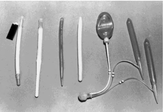
Five different carotid artery vascular clamps (Fig. 9) have been tested for compatibility with MR examina-tions (1,5). Each of the clamps displayed ferrous qual-ities when placed in a 1.5-T static magnetic field (1,5,83). The Poppen-Blaylock carotid artery vascular clamp has exhibited substantial attraction relative to other devices tested. The remaining four, described as being “only slightly ferromagnetic,” have undergone MR examinations in systems up to and including 1.5 T without patients experiencing any discomfort or neuro-logic difficulties (1,5,83). It is recommended that evi-dence of surgical documentation describing the im-Figure 8. Examples of penile prostheses tested for MR safety.
Figure 9. Examples of hemostatic vascular clips considered to be safe for patients undergoing MRI examinations.
planted device and the referring physician be consulted before conducting the MRI procedure.
SUMMARY AND CONCLUSIONS
Pre-MRI procedure screening is crucial to ensure the safety of all those who encounter the MR environment. All biomedical implants, devices, and associated com-ponents such as lead wires should be given special considerations, including those that have obtained FDA approval for claims of MR safety and/or compatibility. Manufacturer guidelines should be obtained and those recommendations regarding MR procedures followed precisely.
The MR environment should always be treated with respect and caution by all who that enter. Finally, all patients should be continuously monitored during MR examinations and encouraged to report any feelings of heating or any other unusual sensations. Communica-tion between the patient and the MR technologist or scan operator should be ongoing and frequent.
ACKNOWLEDGMENTS
Many thanks to Emanuel Kanal, Gary Glover, Maureen Ainslie, Chuck Spritzer, and Marc Jacobskind for con-tributing generous support and time in writing this article. Special thanks to Bob Herfkens for his valuable support; through his knowledge and expertise, he pre-serves Stanford’s safe MR environment.
REFERENCES
1. Shellock F, Kanal E. Magnetic resonance bioeffects, safety, and patient management, 2nd ed. New York: Lippincott-Raven; 1996. 2. Shellock FG, Curtis JS. MR imaging and biomedical implants,
ma-terials, and devices: an updated review. Radiology 1991;180:541– 50.
3. Shellock FG, Kanal E. Policies, guidelines, and recommendations for MR imaging safety and patient management. SMRI Safety Com-mittee. J Magn Reson Imaging 1991;1:97–101.
4. Shellock F, Litwer C, Kanal E. Magnetic resonance imaging: bioef-fects, safety, and patient management. Rev Magn Reson Med 1992; 4:21– 63.
5. Shellock F. Pocket guide to MR procedures and metallic objects: update 2000, New York: Lippincott-Raven; 2000.
6. Johnson GC. Need for caution during MR imaging of patients with aneurysm clips. Radiology 1993;188:287–288.
7. Kanal E, Shellock FG, Talagala L. Safety considerations in MR imaging. Radiology 1990;176:593– 606.
8. Alagona P Jr, Toole JC, Maniscalco BS, et al. Nuclear magnetic resonance imaging in a patient with a DDD Pacemaker [letter]. Pacing Clin Electrophysiol 1989;12:619.
9. Bonnet CA, Elson JJ, Fogoros RN. Accidental deactivation of the automatic implantable cardioverter defibrillator. Am Heart J 1990; 120:696 – 697.
10. ECRI. A new MRI complication. Health Devices Alert. Philadelphia, PA. 1988 ECRI.
11. Erlebacher JA, Cahill PT, Pannizzo F, Knowles RJ. Effect of mag-netic resonance imaging on DDD pacemakers. Am J Cardiol 1986; 57:437– 440.
12. Fetter J, Aram G, Holmes DR Jr, Gray JE, Hayes DL. The effects of nuclear magnetic resonance imagers on external and implantable pulse generators. Pacing Clin Electrophysiol 1984;7:720 –727. 13. Food and Drug Administration. Magnetic resonance diagnostic
de-vice: panel recommendation and report on petitions for MR reclas-sification. Fed Reg 1988, Rockville, MD.
14. Gangarosa RE, Minnis JE, Nobbe J, Praschan D, Genberg RW.
Operational safety issues in MRI. Magn Reson Imaging 1987;5: 287–292.
15. Gegauff AG, Laurell KA, Thavendrarajah A, Rosenstiel SF. A poten-tial MRI hazard: forces on dental magnet keepers. J Oral Rehab 1990;17:403– 410.
16. Hayes DL, Holmes DR Jr, Gray JE. Effect of 1.5 tesla nuclear magnetic resonance imaging scanner on implanted permanent pacemakers. J Am Coll Cardiol 1987;10:782–786.
17. Holmes DR Jr, Hayes DL, Gray JE, Merideth J. The effects of magnetic resonance imaging on implantable pulse generators. Pac-ing Clin Electrophysiol 1986;9:360 –370.
18. Pavlicek W, Geisinger M, Castle L, et al. The effects of nuclear magnetic resonance on patients with cardiac pacemakers. Radiol-ogy 1983;147:149 –153.
19. Persson B, Stahlberg F. Health and safety of clinical NMR exami-nations. Boca Raton, Fl: CRC Press; 1989.
20. Zimmerman B, Faul D. Artifacts and hazards in NMR imaging due to metal implants and cardiac pacemakers. Diagn Imag Clin Med 1984;53:53–56.
21. Food and Drug Administration. Premarket notification: 510(k) reg-ulatory requirements for medical devices. Bethesda, MD: US De-partment of Health and Human Services, Public Health Service, Food and Drug Administration; 1988.
22. Shellock FG. Biological effects and safety aspects of magnetic res-onance imaging. Magn Reson Q 1989;5:243–261.
23. Kanal E, Shellock FG. The value of published data on MR compat-ibility of metallic implants and devices. AJNR 1994;15:1394 –1396. 24. American Society for Testing and Materials (ASTM). Standard spec-ification for the requirements and disclosure of self-closing aneu-rysm clips. In: Annual book of American Society for Testing and Materials Standards, 1994, Philadelphia, PA.
25. Becker RL, Norfray JF, Teitelbaum GP, et al. MR imaging in pa-tients with intracranial aneurysm clips. AJNR 1988;9:885– 889. 26. Dujovny M, Gundamraj NR, Alp MS, Misra M. Aneurysm clip
test-ing for ferromagnetic properties: clip variability issues [comment]. Radiology 1997;202:637.
27. Dujovny M, Kossowsky R, et al. Vascular clips: historic and bio-medical perspective. In: Fein, Flamm, editors. Cerebral vascular surgery. New York: Springer-Verlag; 1985, pp 1–14.
28. Dujovny M, Kossovsky N, Kossowsky R, et al. Aneurysm clip motion during magnetic resonance imaging: in vivo experimental study with metallurgical factor analysis. Neurosurgery 1985;17:543– 548.
29. Fleckenstein JL, Purdy PD, Mendelsohn DB, et al. Aneurysm clip testing for ferromagnetic properties: clip variability issues [com-ment]. Radiology 1997;202:640.
30. Kanal E, Shellock FG, Lewin JS. Aneurysm clip testing for ferro-magnetic properties: clip variability issues. Radiology 1996;200: 576 –578.
31. Kanal E, Shellock F, Lewin J. Reply. Radiology 1997;202:638 – 639. 32. Kanal E, Shellock F, Lewin J. Reply. Radiology 1997;202:641– 642. 33. Klucznik RP, Carrier DA, Pyka R, Haid RW. Placement of a ferro-magnetic intracerebral aneurysm clip in a ferro-magnetic field with a fatal outcome [see comments]. Radiology 1993;187:855– 856. 34. New PF, Rosen BR, Brady JJ, et al. Potential hazards and artifacts
of ferromagnetic and non-ferromagnetic surgical and dental mate-rials and devices in nuclear magnetic resonance imaging. Radiol-ogy 1983;147:139 –148.
35. Shellock F. Pocket guide to MR procedures and metallic objects: update 1997. New York: Lippincott-Raven; 1997.
36. Shellock FG, Crues JV. High-field-strength MR imaging and metal-lic biomedical implants: an ex vivo evaluation of deflection forces. AJR 1988;151:389 –392.
37. Shellock F, Kanal E. Aneurysm clips and MR procedures: evalua-tion of magnetic field interacevalua-tions. SMRT/ISMRM Signals newslet-ter 1998;4:13–15.
38. Shellock FG, Kanal E. Yasargil aneurysm clips: evaluation of inter-actions with a 1.5-T MR system. Radiology 1998;207:587–591. 39. Shellock FG, Shellock VJ. Spetzler titanium aneurysm clips:
com-patibility at MR imaging. Radiology 1998;206:838 – 841.
40. Wichmann W, Von Ammon K, Fink U, Weik T, Yasargil GM. Aneu-rysm clips made of titanium: magnetic characteristics and artifacts in MR. AJNR 1997;18:939 –944.
41. Shellock F. New aneurysm clips made from titanium provide safe alternative for patients undergoing MR procedures. SMRT/ISMRM Signals Newsletter 1997;2:15.
42. Kanal E, Shellock FG. MR imaging of patients with intracranial aneurysm clips. Radiology 1993;187:612– 614.
43. Marshall MW, Teitelbaum GP, Kim HS, Deveikis J. Ferromagnetism and magnetic resonance artifacts of platinum embolization micro-coils. Cardiovasc Intervent Radiol 1991;14:163–166.
44. Gleason CA, Kaula NF, Hricak H, Schmidt RA, Tanagho EA. The effect of magnetic resonance imagers on implanted neurostimula-tors. Pacing Clin Electrophysiol 1992;15:81–94.
45. Liem LA, van Dongen VC. Magnetic resonance imaging and spinal cord stimulation systems. Pain 1997;70:95–97.
46. Schroeder PM, Miksicek A, Koralewski HE, Ro¨mer T. Magnetic resonance tomography in patients with nerve pacemakers. Rofo Fortschritte Gebiete Rontgenstrahlen Nuklearmedizin 1987;147: 198 –199.
47. Cyberonics. Web site: http://www.cyberonics.com. 1999. 48. Tronnier VM, Staubert A, Ha¨hnel S, Sarem-Aslani A. Magnetic
resonance imaging with implanted neurostimulators: an in vitro and in vivo study. Neurosurgery 1999;44:118 –125; discussion 125–126.
49. Chou CK, McDougall JA, Chan KW. RF heating of implanted spinal fusion stimulator during magnetic resonance imaging. IEEE Trans Biomed Eng 1997;44:367–373.
50. EBI. SpF-2T implantable, monitorable spinal fusion stimulator System. Physician’s manual. Parsippany, NJ: EBI Medical Sys-tems; 1998.
51. Shellock F. MRI and the implantable spinal fusion stimulator. SMRT/ISMRM Signals Newsletter 1998;2:10.
52. Shellock F. Pocket guide to MR procedures and metallic objects: update 1998. New York: Lippincott-Raven; 1998.
53. Shellock FG, Hatfield M, Simon BJ, et al. Implantable spinal fusion stimulator: assessment of MRI safety. J Magn Reson Imaging (in press).
54. von Roemeling R, Lanning RM, Eames FA. MR imaging of patients with implanted drug infusion pumps. J Magn Reson Imaging 1991; 1:77– 81.
55. Shellock FG, Morisoli S, Kanal E. MR procedures and biomedical implants, materials, and devices: 1993 update. Radiology 1993; 189:587–599.
56. Randall PA, Kohman LJ, Scalzetti EM, Szeverenyi NM, Panicek DM. Magnetic resonance imaging of prosthetic cardiac valves in vitro and in vivo. Am J Cardiol 1988;62:973–976.
57. Shellock FG, Morisoli SM. Ex vivo evaluation of ferromagnetism, heating, and artifacts produced by heart valve prostheses exposed to a 1.5 T MR system. J Magn Reson Imaging 1994;4:756 –758. 58. Soulen RL, Budinger TF, Higgins CB. Magnetic resonance imaging
of prosthetic heart valves. Radiology 1985;154:705–707. 59. Soulen RL, Higgins CB. Magnetic resonance imaging of the
cardio-vascular system. Magnetic Resonance Annual 1985;8:27– 43. 60. Young DB, Pawlak AM. An electromagnetically controllable heart
valve suitable for chronic implantation. Asaio Trans 1990;36: M421– 425.
61. Bakshandah H, Shellock F, Schatz C, Morisoli S. Metallic clips used for scleral buckling: ex vivo evaluation of ferromagnetism determined at 1.5T. J Magn Reson Imaging 1993;3:559. 62. Yuh W, Hanigan M, Nerad J, et al. Extrusion of an eye socket
magnetic implant after MR imaging examination: potential hazard to a patient with eye prosthesis. J Magn Reson Imaging 1991;1: 711–713.
63. Shellock FG. MR imaging of metallic implants and materials: a compilation of the literature. AJR 1988;151:811– 814.
64. Applebaum EL, Valvassori GE. Effects of magnetic resonance im-aging fields on stapedectomy prostheses. Arch Otolaryngol 1985; 111:820 – 821.
65. Applebaum EL, Valvassori GE. Further studies on the effects of magnetic resonance imaging fields on middle ear implants. Ann Otol Rhinol Laryngol 1990;99:801– 804.
66. Nogueira M, Shellock F. Otologic bioimplants: ex vivo assessment of ferromagnetism and artifacts at 1.5 Tesla. AJR 1995;63:1472– 1473.
67. Dormer KJ, Richard GL, Hough JV, Nordquist RE. The use of rare-earth magnet couplers in cochlear implants. Laryngoscope 1981;91:1812–1820.
68. Mattucci KF, Setzen M, Hyman R, Chaturvedi G. The effect of nuclear magnetic resonance imaging on metallic middle ear pros-theses. Otolaryngol Head Neck Surg 1986;94:441– 443.
69. Shellock FG, Nogueira M, Morisoli S. MR imaging and vascular access ports: ex vivo evaluation of ferromagnetism, heating, and artifacts at 1.5 T. J Magn Reson Imaging 1995;5:481– 484. 70. Shellock FG, Shellock VJ. Vascular access ports and catheters: ex
vivo testing of ferromagnetism, heating, and artifacts associated with MR imaging. Magn Reson Imaging 1996;14:443– 447. 71. Shellock F, Meeks T. Ex vivo evaluation of ferromagnetism and
artifacts for implantable vascular access ports exposed to a 1.5T scanner. J Magn Reson Imaging 1991;1:243.
72. Girard MJ, Hahn PF, Saini S, et al. Wallstent metallic biliary en-doprosthesis: MR imaging characteristics. Radiology 1992;184: 874 – 876.
73. Kiproff PM, Deeb ZL, Contractor FM, Khoury MB. Magnetic reso-nance characteristics of the LGM vena cava filter: technical note. Cardiovasc Intervent Radiol 1991;14:254 –255.
74. Shellock FG, Detrick MS, Brant-Zawadski MN. MR compatibility of Guglielmi detachable coils. Radiology 1997;203:568 –570. 75. Shellock FG, Shellock VJ. Metallic stents: evaluation of MR imaging
safety. AJR 1999;173:543–547.
76. Teitelbaum GP, Bradley WG Jr, Klein BD. MR imaging artifacts, ferromagnetism, and magnetic torque of intravascular filters, stents, and coils. Radiology 1988;166:657– 664.
77. Teitelbaum GP, Raney M, Carvlin MJ, Matsumoto AH, Barth KH. Evaluation of ferromagnetism and magnetic resonance imaging artifacts of the Strecker tantalum vascular stent. Cardiovasc Inter-vent Radiol 1989;12:125–127.
78. Teitelbaum GP, Ortega HV, Vinitski S, et al. Low-artifact intravas-cular devices: MR imaging evaluation. Radiology 1988;168:713– 719.
79. Strohm O, Kivelitz D, Gross W, et al. Safety of implantable coronary stents during1
H magnetic resonance imaging at 1.0T and 1.5T. J Cardiovasc Magn Reson Imaging 1999;1:239 –245.
80. Jost C, Kumar V. Are current cardiovascular stents MRI safe? J Invas Cardiol 1998;10:477– 479.
81. Liang MD, Narayanan K, Kanal E. Magnetic ports in tissue ex-panders—a caution for MRI. Magn Reson Imaging 1989;7:541– 542.
82. Shellock F, Crues J, Sacks S. High-field magnetic resonance imag-ing of penile prostheses: in vitro evaluation of deflection forces and imaging artifacts. In: Proceedings of the Society of Magnetic Reso-nance in Medicine Annual Meeting, Berkeley, CA 1987.
83. Teitelbaum GP, Lin MC, Watanabe AT, et al. Ferromagnetism and MR imaging: safety of carotid vascular clamps. AJNR 1990;11:267– 272.