Features
• Loop-type sensor fibre, radial sensor fibre or lens-type sensor for arc detection • Two high-speed semiconductor outputs fortripping
• Tripping from light only or secured with fast, adjustable three-phase overcurrent condition
• Total operate time <2.5 ms
• Wide area automatic or manual backlight compensation
• Two RJ45 ports for chaining the extension units
• Two opto-connectors for fast ON/OFF sig-nal transfer between central units
• Circuit-breaker failure protection, i.e. delayed output for higher-level circuit breaker
• Self-supervision unit for monitoring the sensor fibre, operating voltages and cabling between central units and exten-sion units
Application
Consequences of an arcing short circuit fault within a low/medium voltage switchgear can be very serious. An arc can destroy costly equipment, and cause prolonged and expen-sive downtime. Furthermore, an arc can cause serious injuries to personnel.Sources of arcing can be e.g. failure of insula-tion, mal-operation of a device, improper bus or cable joints, overvoltage, corrosion, pollu-tion, moisture, ferro-resonance (instrument transformers) and even ageing under electri-cal stress. Most of these could be prevented by sufficient maintenance. But in spite of all precautions, human errors by personnel can also lead to arc faults.
Time is critical when it comes to detecting and minimising the effects of an arc. An arc fault lasting 500 ms may cause severe dam-age to the installation. If the arc lasts less than 100 ms the damage is often smaller, but if the arc is eliminated in less than 35 ms the dam-age is almost unnoticed.
Normally applied bus bar protection relaying arrangements may be too slow to ensure safe fault clearance times at arc faults. E.g. opera-tion time of the overcurrent relay controlling the incoming CB may have to be delayed hundreds of milliseconds for selectivity rea-sons. This delay can be avoided using REA 10_ arc protection system: Total fault clear-ance time can be reduced to max 2.5 ms plus circuit breaker’s action time.
Furthermore, autoreclosures at cable com-partment faults can be eliminated with arc protection.
The arc protection relay REA 101 and the extension units REA 103, REA 105 and REA 107 are designed to be used for the protection of medium and low-voltage air-insulated switchgear. The central unit type REA 101 operates independently or together with the extension units REA 103, REA 105 and REA 107. These extension units allow the number of sensor fibres and/or lens sensors to be increased, thus extending the area to be
pro-tected. In an arc situation, the fault place is quickly localized by inspecting the area cov-ered by the sensor that detected the arc. The design of the extension units REA 103 and REA 105 is nearly the same. The main differ-ence between the units is that the REA 105 is provided with two fast trip outputs capable of opening, for example, the bus coupler or both
circuit breakers of a duplex feeder. Thus selective tripping is achieved. The REA 107 is also used for the extension of the protection area. It has inputs for eight lens-type sensors. The arc protection relay REA 101 is provided with two output ports, to each of which a maximum of five extension units can be chained.
Design
Arc protection relay REA 101
Current indication unitThe three phase currents are measured via transformers. An overcurrent signal is acti-vated once the current on one phase exceeds the reference level. The SG1/1-4 switches are used for selecting the reference level. Avail-able current level settings are 0.5, 1.0, 1.5, 2.5, 3.0, 5.0 and 6.0 times the rated current (In= 1.0 A or 5.0 A).
Light detection unit
The switch SG1/6 is used for activating the sensor. Automatic or manual backlight com-pensation reference level is selected with the switch SG1/5.
The light captured by the sensor is amplified and compared to pre-selected reference level. Once the light exceeds the set reference level, a light signal is activated.
When an automatic reference level has been selected, the unit forms the reference level based on the backlight intensity measured by the sensor.
When a manual reference level has been selected, the unit forms the reference level based on the value set by the potentiometer (Light Ref. Level Adj.) on the front panel.
The condition of the sensor fibre is monitored by sending a test pulse through the fibre. Unless the test pulse is received at regular intervals at the other end of the loop, the sen-sor fault LED (Sensen-sor Fault) and the self-supervision LED (IRF) are activated and the IRF relay resets. If the sensor-monitoring fea-ture is not needed, it can be deactivated by means of switch SG3/4. Then no test pulse will be sent and a radial, i.e. terminating sen-sor fibre can be used.
Trip output
The trip output is provided with two galvani-cally isolated, high-speed IGBT
semiconduc-The control signal of the outputs is activated if the overcurrent signal and the light signal, but not the operating voltage fault signal, are active at the same time.
If tripping is to be activated by an arc alone, the overcurrent signal can be set to be con-stantly active by means of the key switch Trip Condition located on the front panel. When a trip signal is delivered, the trip outputs are locked in the activated state. The Reset push-button on the front panel or a reset signal applied to the RESET input can be used to reset the outputs.
Ports A and B for the connection of exten-sion units
Ports A and B are activated using the switches SG1/7-8. The extension units con-nect to the ports via concon-nection cables. The extension unit receives its operating voltages and operation signals over the port. The ports are protected against short circuit and cable breaks. If the connection cable from a port breaks, the concerned chain is disconnected and the fault LED (Port A Fault or Port B Fault) of the port and the IRF indicator on the central unit activated, and the IRF relay resets. A maximum of 5 extension units can be connected to one port. If an extension unit included in the chain connected to the port is damaged, then the fault LED of the port starts flashing, the IRF indicator is lit and the IRF relay resets.
Communication REA101/REA101 (optolink)
The REA 101 relay contains two communica-tion links: Optolink 1 and Optolink 2. The SG2/1-8 switches are used to select the links to be used and the messages to be communi-cated between them. Each link can be pro-grammed either as a transmitter or as a receiver.
The purpose of the communication link is to communicate ON/OFF type messages between the central units, over the signal
sage per optolink is allowed to be transmitted between the central units. The data to be com-municated depends on the system design.
To monitor the connection, a test pulse is sent through the signal transfer fibre at regular intervals. Should the test pulse not be received at the specified time, the optolink fault LED (Optolink 1 Fault, Optolink 2 Fault) and the IRF indicator of the central unit will be lit, and the IRF relay resets.
Circuit-breaker failure protection (CBFP)
The circuit-breaker failure protection has been implemented by delaying either the HSO2 output or the TRIP3 output, or when required, both outputs. The switches SG3/1-3 are used for selecting the desired alternative.
If both outputs are used, it should be noted that the delay time is the same, but the pickup time of the relay (5…15 ms) has been added to the TRIP3 relay.
The selected delay time, i.e. 100 ms or 150 ms, starts running once the HSO1 is acti-vated. Delayed tripping does not take place if the overcurrent signal disappears before the specified time delay elapses.
When the circuit-breaker failure protection is out of use, all the trip outputs operate in par-allel.
Self-supervision unit (IRF)
In addition to that mentioned above, the self-supervision unit monitors the operating volt-age of the relay. Should a fault be detected in the operating voltages, the self-supervision unit will prevent the relay from operating. In addition, the IRF indicator is lit and the IRF relay resets.
Extension unit REA 103
The REA 103 is an extension unit designed to be used together with the arc protection relay REA 101. The function of the unit is to detect light and to provide the REA 101 relay with information about this. The use of the exten-sion unit allows the protection area to be extended and the object to be divided into smaller areas.
The REA 103 arc protection unit has the fol-lowing features:
• two sensor fibres for arc detection, loop or radial arrangement
• two signal relays for each sensor fibre
• relays activated by light detected by the sensor fibre
• two RJ45 ports for the connection of REA 101 relay and extension units • self-supervision unit monitoring operating
voltages and sensor fibre loops
Extension unit REA 105
The REA 105 is an extension unit designed to be used together with the arc protection relay REA 101. The function of the unit is to detect light and to carry out tripping, if the REA 101 relay provides an overcurrent signal at the same time, or delivers a trip command.
The use of the extension unit allows the pro-tection area to be extended and the protected object to be divided into smaller areas. Thus a more selective system is obtained.
The REA 105 arc extension unit has the fol-lowing features:
• loop-type or radial sensor fibre for arc pro-tection
• two high-speed semiconductor outputs for tripping
• signal relay activated by light detected by the sensor fibre
• three RJ45 ports for the connection of REA 101 and extension units; additional RJ45 port allows REA 105 to be used as a link between two REA 101 relays
• circuit-breaker failure protection. Delayed light signal to REA 101, which opens the higher-level circuit breaker
• self-supervision unit monitoring operating voltages and the sensor fibre loop
Extension unit REA 107
The REA 107 is an extension unit designed to be used together with the arc protection relay REA 101. The function of the unit is to detect light and to provide the REA 101 relay with information about this. The use of the exten-sion unit allows the protection area to be extended and the object to be divided into smaller areas.
The REA 107 arc extension unit has the fol-lowing features:
• eight lens-type sensors for arc detection • two signal relays
• two RJ45 ports for the connection to the host REA 101 or other extension units • self-supervision of operating voltages • LED indicators for each sensor
Technical data
7DEOH&XUUHQWLQSXWRated current 1 A / 5 A
Continuous load current 4 A / 20 A
Momentary current for 1 s 100 A / 500 A
Dynamic current withstand, half-wave value 250 A / 1250 A
Input impedance <100 mΩ / <20 mΩ
Rated frequency 50 or 60 Hz
7DEOH2XWSXWV
Trip contacts HSO1 and HSO2 Max system voltage 250 V dc/ac
Continuous carry 1.5 A
Continuous carry (REA 105) 1.0 A
Make and carry for 0.5 s 30 A
Make and carry for 3 s 15 A
Breaking capacity for dc, when the control circuit time constant L/R < 40 ms, at 48/110/220 V dc
5 A / 3 A / 1 A
Trip contact TRIP3 Max system voltage 250 V dc/ac
Continuous carry 5 A
Make and carry for 0.5 s 30 A
Make and carry for 3 s 15 A
Breaking capacity for dc, when the control circuit time constant L/R < 40 ms, at 48/110/220 V dc
5 A / 3 A / 1 A
Signal contacts IRF Max system voltage 250 V dc/ac
Continuous carry 5 A
Make and carry for 0.5 s 10 A
Make and carry for 3 s 8 A
Breaking capacity for dc, when the control circuit time constant L/R < 40 ms, at 48/110/220 V dc
1 A / 0.25 A / 0.15 A
7DEOH5(6(7LQSXW
Control voltages Rated voltages and operating
ranges
Un = 24/48/60/110/220 V dc 18...265 V dc
Un = 110/120/220/240 V ac 18...265 V ac
not active, when control voltage <9 V dc, 6 V ac
Control current 1.5…20 mA
Minimum pulse length >0.6 s
7DEOH&LUFXLWEUHDNHUIDLOXUHSURWHFWLRQ&%)3
Selectable operate time delays 150 ms / 100 ms
Operate time accuracy HSO2 ±5% of setting value
TRIP3 ±5% of setting value +5…15 ms
7DEOH3RZHUVXSSO\
Relay type 1MRS090416-AAA Un = 110/120/220/240 V ac
85…110% of Un ac Un = 110/125/220 V dc 80…120% of Un dc
Relay type 1MRS090416-CAA Un = 24/48/60 V dc
7DEOH3RZHUFRQVXPSWLRQ
REA 101 Power consumption of relay under
quiescent/operating conditions
~9 W / ~12 W
Max. port output power ~19 W
Max. number of extension units/port
5
Max. power consumption with 10 extension units connected
<50 W
REA 103
(operating voltage over the port of REA 101)
Power consumption of relay under quiescent/operating conditions
~1.6 W / ~3.3 W
REA 105
(operating voltage over the port of REA 101)
Power consumption of relay under quiescent/operating conditions
~2.7 W / ~3.7 W
REA 107
(operating voltage over the port of REA 101)
Power consumption of relay under quiescent/operating conditions
~1.7 W / ~2.7 W
7DEOH6HQVRUILEUH
Maximum length without splices or one splice 60 m
Maximum length with two splices 50 m
Maximum length with three splices 40 m
Service temperature range -35…+80°C
Smallest permissible bending radius 50 mm
7DEOH&RQQHFWLRQFDEOH
Total length of the connection chain 40 m
7DEOH2SWROLQNFRPPXQLFDWLRQ
Max. length of signal transfer plastic fibre 40 m Max. length of signal transfer glass fibre 2000 m
7DEOH6HWWLQJUDQJH
Current setting steps In x 0.5, 1.0, 1.5, 2.5, 3.0, 5.0, 6.0
Operation accuracy ±5% of the setting value
7DEOH7RWDORSHUDWHWLPH
HSO1 and HSO2 ≤2.5 ms
TRIP3 <15 ms
7DEOH(QYLURQPHQWDOWHVWV
Specified service temperature range -10…+55°C
Transport and storage temperature range -40…+70°C
Operation in dry heat conditions Acc. to IEC 60068-2-2 (BS 2011:Part 2.1 B) Operation in dry cold conditions Acc. to IEC 60068-2-1 (BS 2011:Part 2.1 A)
Damp heat test cyclic Acc. to IEC 60068-2-30 (BS 2011:Part 2.1 Db)
r.h. >95%, t=20…55°C
Technical data (cont´d) 7DEOH(QFDSVXODWLRQ
REA 101 Degree of protection, IEC 60529 IP 20
Weight about 4.6 kg
REA 103 Degree of protection, IEC 60529 IP 20
Weight about 1.1 kg
REA 105 Degree of protection, IEC 60529 IP 20
Weight about 1.1 kg
REA 107 Degree of protection, IEC 60529 IP 20
Weight about 1.0 kg
7DEOH,QVXODWLRQWHVWV
Dielectric tests acc. to IEC 60255-5 2 kV, 50 Hz, 1 min. Impulse voltage test acc. to IEC 60255-5 5 kV, 1.2/50 µs, 0.5 J Insulation resistance acc. to IEC 60255-5 >100 MΩ, 500 V dc 7DEOH0HFKDQLFDOWHVWV
Vibration tests (sinusoidal) acc. to IEC 60255-21-1 class 1 Shock and bump test acc. to IEC 60255-21-2 class 1
Seismic test acc. to IEC 60255-21-3 class 2
7DEOH(OHFWURPDJQHWLFFRPSDWLELOLW\ 1 MHz burst disturbance test,
acc. to IEC 60255-22-1, class III
common mode 2.5 kV
differential mode 1 kV
Electrostatic discharge test, acc. to IEC 61000-4-2, class III
contact discharge 6 kV
air discharge 8 kV
Radio-frequency electromagnetic field disturbance test acc. to IEC 61000-4-3
frequency f 80…1000 MHz
field strength E 10 V/m (rms)
Radio frequency disturbance test, (conducted, common mode) acc. to IEC 61000-4-6
10 V, 150 kHz…80 MHz
Fast transient disturbance tests acc. to IEC 255-22-4 and IEC 61000-4-4
4 kV
Surge immunity test acc. to IEC 61000-4-5: aux. voltage input, current inputs, trip outputs (REA 101)
common mode 4 kV
differential mode 2 kV
Surge immunity test acc. to IEC 61000-4-5: trip outputs (REA 105)
common mode 4 kV
differential mode 2 kV
Surge immunity test acc. to IEC 61000-4-5: signal contacts (IRF), RESET input (REA 101)
common mode 2 kV
differential mode 1 kV
Surge immunity test acc. to IEC 61000-4-5: signal output contacts (REA 103, REA 105 and REA 107)
common mode 2 kV
differential mode 1 kV
Electromagnetic emissions tests acc. to EN 55011 and EN 50081-2
conducted RF emission (mains terminal), REA 101
EN 55011, class A
radiated RF emission EN 55011, class A
7DEOH&(DSSURYDO
Block diagram
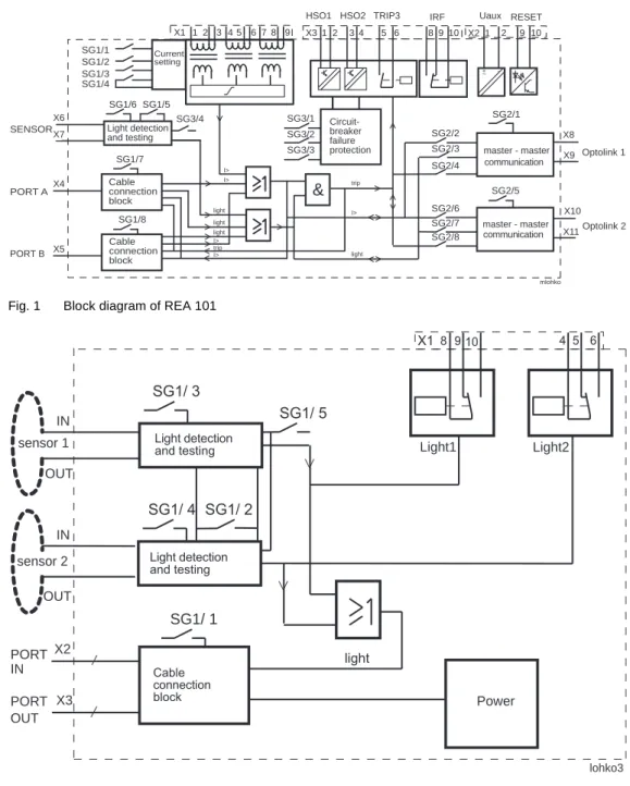
Fig. 1 Block diagram of REA 101
& master - master master - master SG1/2 SG1/1 SG1/3 SG1/4 SG3/1 SG3/2 SG3/3 SG3/4 SG1/5 SG1/6 SG1/7 SG1/8 SG2/2 SG2/3 SG2/4 SG2/5 SG2/8 SG2/7 SG2/6 SG2/1 X1 1 2 3 4 5 6 7 8 9 X6 X7 X4 X5 SENSOR X8 X9 X10 X11 PORT B PORT A X3 1 2 3 4 5 6 8 9 10 X2 1 2 9 10
HSO2 TRIP3 IRF Uaux RESET
trip I> I> I> I> light light light light I> trip Optolink 1 Optolink 2 HSO1 + ~ -mlohko Circuit-breaker failure protection communication communication Light detection and testing Cable connection block Cable connection block Current setting
Fig. 2 Block diagram of REA 103
lohko3 Power X1 9 10 4 5 6 SG1/ 1 SG1/ 2 SG1/ 3 SG1/ 4 SG1/ 5 sensor 1 sensor 2 IN OUT IN OUT PORT PORT IN OUT light 8 Light1 Light2 X2 X3 Cable connection block Light detection and testing Light detection and testing
Fig. 3 Block diagram of REA 105
&
HSO1 HSO2 sensor 1 SG1/ 1 SG1/ 2 SG1/ 3 SG1/ 4 SG1/ 5 SG1/ 7 SG1/ 6 SG1/ 8 X4 1 2 3 6 7 9 10 PORT IN 1 PORT IN 2 PORT OUT 1 I> I> trip trip light Power IN OUT X2 X3 X1 loh5a³
1
³
1
³
1
Circuit-breaker failure protection Light detection and testing Cable connection block Cable connection blockFig. 4 Block diagram of REA 107
SG1/ 1 sensor 1
Light
sensor 2 sensor 3 sensor 4 sensor 5 sensor 6 sensor 7 sensor 8
SG1/ 2 ≥1 X1 Light 1-4 Light 5-8 4 5 6 8 9 10 PORT IN PORT OUT Cable connection block ≥1 ≥1 Light detection Light detection Light detection Light detection Light detection Light detection Light detection Light detection Lohko7 Power SG1/3 SG1/4 SG1/5 SG1/6 SG1/7 SG1/8
Dimensions
Dimension drawings
Mounting alternatives
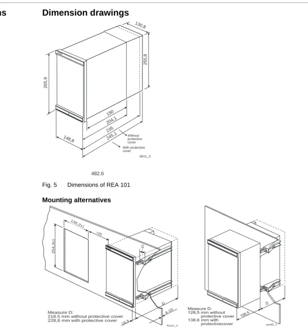
Fig. 5 Dimensions of REA 101 dim1_3 148,8 265,9 130,8 255,8 190 204,1 235 245,1 ABB 482.6 With protective cover Without protective cover
Fig. 6 Flush mounting and semi-flush mounting of REA 101
4-10 ABB flush1_3 16,5 D 135,2 ±1 254,3 ±1 >20 ~15 Measure D:
218.5 mm without protective cover 228,6 mm with protective cover
semifl1_3 D 106,5 Measure D: 128,5 mm without protective cover 138.6 mm with protectivecover
Fig. 7 Surface mounting of REA 101
wallmoun. A B C Wall M4x6 TORX M5x8 TORX M6x12 TORX
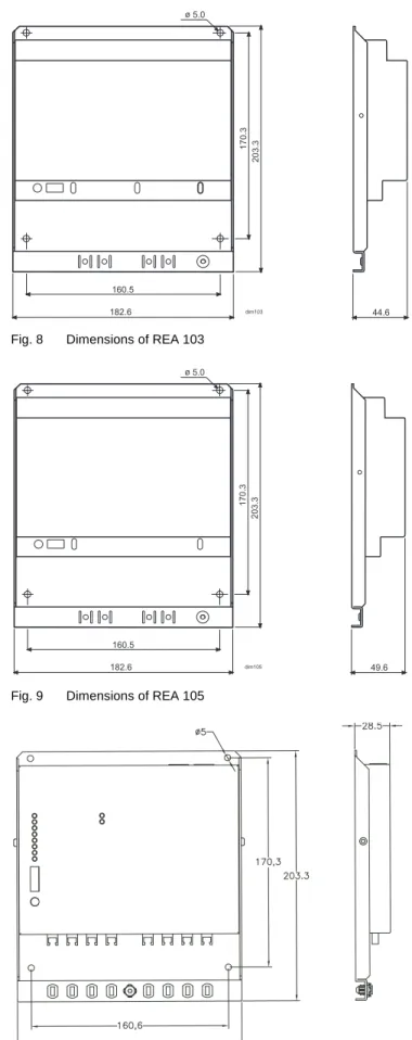
Fig. 8 Dimensions of REA 103 44.6 203.3 182.6 170.3 160.5 ø 5.0 dim103
Fig. 9 Dimensions of REA 105
49.6 203.3 182.6 170.3 160.5 ø 5.0 dim105
Ordering
:KHQRUGHULQJSOHDVHVSHFLI\Ordering information Ordering example
1. Type designation and quantity REA 101, 5 pieces
2. Order number 1MRS 090416-AAA
3. Auxiliary voltage Uaux=110 V dc
4. Accessories Connection cables 5m, 1MRS 120511.005, 5 pieces
Pre-manufactured fibre sensors 10 m, 1MRS 120512.010, 13 pieces Pre-manufactured lens sensors 7 m, 1MRS 120534-7.0, 16 pieces
5. Number of REA 103 units 3
6. Number of REA 105 units 2
7. Number of REA 107 units 2
2UGHUQXPEHUV
Arc protection relay REA 101 Un = 110…240 V ac Un = 110…220 V dc
1MRS 090416-AAA *)
Arc protection relay REA 101 Un = 24…60 V dc
1MRS 090416-CAA *)
Arc protection relay REA 101 with optolink connectors for glass fibre
Un = 110…240 V ac
Un = 110…220 V dc
1MRS 090416-AAAG *)
Arc protection relay REA 101 with optolink connectors for glass fibre
Un = 24…60 V dc
1MRS 090416-CAAG *)
Rear plate protective cover 1MRS 060196
Mounting kit for semi-flush mounting 1MRS 050254
Mounting kit for surface mounting 1MRS 050240
Mounting kit for connecting cases together 1MRS 050241
Mounting kit for 19” rack 1MRS 050258
Extension unit REA 103 1MRS 090417-AA
Extension unit REA 105 1MRS 090418-AA
Extension unit REA 107 REA 107-AA
*) Includes mounting kit 1MRS 050209 for flush mounting 3UHPDQXIDFWXUHGILEUHVHQVRUV
Length Order number
5 m ±3% 1MRS 120512.005 10 m ±3% 1MRS 120512.010 15 m ±3% 1MRS 120512.015 20 m ±3% 1MRS 120512.020 25 m ±3% 1MRS 120512.025 30 m ±3% 1MRS 120512.030 40 m ±3% 1MRS 120512.040 50 m ±3% 1MRS 120512.050 60 m ±3% 1MRS 120512.060 $FFHVVRULHVIRUPDQXIDFWXULQJILEUHVHQVRUV Sensor fibre 100 m 1MSC 380018.100 Sensor fibre 300 m 1MSC 380018.300 Sensor fibre 500 m 1MSC 380018.500
ST connector SYJ-ZBC 1A1
ST splice adapter SYJ-ZBC 1A2
*) Note! Lengths over 100 m on request, max. length 2000 m 3UHPDQXIDFWXUHGOHQVVHQVRUVIRU5($ 1,5 m ±3% 1MRS 120534-1.5 3 m ±3% 1MRS 120534-3.0 5 m ±3% 1MRS 120534-5.0 7 m ±3% 1MRS 120534-7.0 10 m ±3% 1MRS 120534-10 15 m ±3% 1MRS 120534-15 20 m ±3% 1MRS 120534-20 25 m ±3% 1MRS 120534-25 30 m ±3% 1MRS 120534-30 3UHPDQXIDFWXUHGOHQVVHQVRUVIRU5($5($DQG5($ 2 m ±3% 1MRS 120536-2 3 m ±3% 1MRS 120536-3 5 m ±3% 1MRS 120536-5 10 m ±3% 1MRS 120536-10 6SDUHSDUWVIRUOHQVVHQVRUV
Light collecting lens 1MRS060743
&DEOHVIRUFRQQHFWLQJ5($WRDQH[WHQVLRQXQLWRUH[WHQVLRQXQLWVWRHDFK DQRWKHU 1 m ±3% 1MRS 120511.001 3 m ±3% 1MRS 120511.003 5 m ±3% 1MRS 120511.005 10 m ±3% 1MRS 120511.010 15 m ±3% 1MRS 120511.015 20 m ±3% 1MRS 120511.020 30 m ±3% 1MRS 120511.030 40 m ±3% 1MRS 120511.040 3ODVWLFILEUHRSWROLQNIRUVLJQDOWUDQVIHUEHWZHHQFHQWUDOXQLWV 1 m ±3% SPA-ZF AA 1 2 m ±3% SPA-ZF AA 2 3 m ±3% SPA-ZF AA 3 5 m ±3% SPA-ZF AA 5 10 m ±3% SPA-ZF AA 10 20 m ±3% SPA-ZF AA 20 30 m ±3% SPA-ZF AA 30 40 m ±3% 1MRS 120517 *ODVVILEUHRSWROLQNIRUVLJQDOWUDQVIHUEHWZHHQFHQWUDOXQLWV 50 m ±3% SPA-ZF1MM50 60 m ±3% SPA-ZF1MM60 70 m ±3% SPA-ZF1MM70 80 m ±3% SPA-ZF1MM80 90 m ±3% SPA-ZF1MM90 100 m ±3% *) SPA-ZF1MM100
References
$GGLWLRQDOLQIRUPDWLRQREA 101 Operator’s Manual 1MRS 751003-MUM EN
REA 103 Operator’s Manual 1MRS 751004-MUM EN
REA 105 Operator’s Manual 1MRS 751005-MUM EN