A Novel Design of a Cable-driven Active Leg Exoskeleton (C-ALEX) and Gait Training with Human Subjects
Xin Jin
Submitted in partial fulfillment of the requirements for the degree of
Doctor of Philosophy
in the Graduate School of Arts and Sciences COLUMBIA UNIVERSITY
© 2017 Xin Jin All rights reserved
ABSTRACT
A Novel Design of a Cable-driven Active Leg Exoskeleton (C-ALEX) and Gait Training with Human Subjects
Xin Jin
Exoskeletons for gait training commonly use a rigid-linked “skeleton” which makes them heavy and bulky. Cable-driven exoskeletons eliminate the rigid-linked skeleton structure, therefore creating a lighter and more transparent design. Current cable-driven leg exoskeletons are limited to gait assistance use. This thesis presented the Cable-driven Active Leg Exoskeleton (C-ALEX) designed for gait retraining and rehabilitation. Bene-fited from the cable-driven design, C-ALEX has minimal weight and inertia (4.7 kg) and allows all the degrees-of-freedom (DoF) of the leg of the user. C-ALEX uses an assist-as-needed (AAN) controller to train the user to walk in a new gait pattern.
A preliminary design of C-ALEX was first presented, and an experiment was done with this preliminary design to study the effectiveness of the AAN controller. The result on six healthy subjects showed that the subjects were able to follow a new gait pattern significantly more accurately with the help of the AAN controller. After this experiment, C-ALEX was redesigned to improve its functionality. The improved design of C-ALEX is lighter, has more DoFs and larger range-of-motion. The controller of the improved design improved the continuity of the generated cable tensions and added the function to estimate the phase of the gait of the user in real-time.
With the improved design of C-ALEX, an experiment was performed to study the effect of the weight and inertia of an exoskeleton on the gait of the user. C-ALEX was used
to simulate exoskeletons with different levels of weight and inertia by adding extra mass and change the weight compensation level. The result on ten subjects showed that adding extra mass increased step length and reduced knee flexion. Compensating the weight of the mass partially restored the knee flexion but not the step length, implying that the inertia of the mass is responsible for the change. This study showed the distinctive effect of weight and inertia on gait and demonstrated the benefit of a lightweight exoskeleton.
C-ALEX was designed for gait training and rehabilitation, and its training effective-ness was studied in nine healthy subjects and a stroke patient. The healthy subjects trained with C-ALEX to walk in a new gait pattern with 30% increase in step height for 40 min. After the training, the subjects were able to closely repeat the trained gait pattern without C-ALEX, and the step height of the subjects increased significantly. A stroke patient also tested C-ALEX for 40 minutes and showed short-term improvements in step length, step height, and knee flexion after training. The result showed the effectiveness of C-ALEX in gait training and its potential to be used in stroke rehabilitation.
Contents
List of Figures iv List of Tables vi Acknowledgements vii Introduction 1 Exoskeletons in Rehabilitation . . . 1Limitations of the Rigid-link Based Designs . . . 3
Cable-driven Designs . . . 5
Overiew of the Thesis . . . 7
1 A Preliminary Design of C-ALEX and Evaluation on Healthy Subjects 9 1.1 The Mechanical Design . . . 9
1.2 The Controller for Gait Assistance . . . 12
1.3 Evaluation on Healthy Subjects . . . 21
1.4 Conclusion . . . 25
2 An Improved Design of C-ALEX 27 2.1 Improvements in the Mechanical Design . . . 27
2.2 Improvements in the Controller . . . 31
2.3 Conclusion . . . 36
3 Effects of Exoskeleton Weight and Inertia on Human Walking 37 3.1 Experiment Protocol . . . 37
3.2 Experiment Results . . . 40
3.3 Discussion . . . 43
3.4 Conclusion . . . 46
4 Gait Training with C-ALEX on Healthy Subjects 47 4.1 Experiment Protocol . . . 47
4.2 Data Processing and Statistical Analysis . . . 51
4.3 Experiment Result . . . 53
4.4 Discussion . . . 59
4.5 Conclusion . . . 62
5 Evaluation of C-ALEX on a Stroke Patient 63 5.1 Experiment Protocol . . . 64
5.2 Data Processing and Statistical Analysis . . . 65
5.3 Experiment Results . . . 66
5.4 Discussion . . . 69
5.5 Conclusion . . . 70
Contributions and Future Works 71 Contributions . . . 71
Future Works . . . 73
List of Figures
1.1 The Preliminary Design of C-ALEX . . . 10
1.2 A Schematic of a Two-link System Actuated by a Single Cable . . . 15
1.3 A Block Diagram of the Controller of C-ALEX . . . 18
1.4 Force Field Controller of C-ALEX . . . 20
1.5 The Experimental Setup to Evaluate the Preliminary Design of C-ALEX . . . 22
1.6 The Experiment Protocol to Evaluate the Preliminary Design of C-ALEX . . 22
1.7 Ankle Path from a Representative Subject . . . 24
1.8 The Normalized Tracking Errors of the AS and TR session . . . 25
2.1 Improved Design of C-ALEX . . . 28
2.2 Improved “Assist-as-needed” Controller . . . 35
3.1 The Average RMS Torque Tracking Error during the Experiment . . . 41
3.2 Hip and Knee Joint Angle of a Gait Cycle during Selected Sessions . . . 41
3.3 Averaged Kinematic Results from the Experiment . . . 42
4.1 The Experiment Setup for Gait Training Experiment with C-ALEX . . . 48
4.2 Generating Target Ankle Trajectory for Gait Training with C-ALEX . . . 49
4.3 Experiment Protocol for Gait Training with C-ALEX . . . 50
4.5 Ankle Trajectories during the Post-training Sessions . . . 55
4.6 Kinematic Results from Selected Sessions of the Training Experiment . . . . 57
5.1 Experiment Setup for Stroke Patient Training with C-ALEX . . . 63
5.2 Generating Target Ankle Trajectory for the Stroke Patient . . . 64
5.3 The Experiment Protocol for Training the Stroke Patient . . . 65
5.4 Ankle Trajectories of the Stroke Patient during Selected Sessions . . . 67
List of Tables
1.1 DH Parameters of the Preliminary Design . . . 11
2.1 DH Parameters of the Improved Design. . . 30
3.1 Experiment Conditions to Study the Effect of Weight and Inertia. . . 39
3.2 Range of Motion of C-ALEX in Degrees. . . 40
4.1 Conditions of the Post-training Sessions . . . 51
Acknowledgements
The path to a doctorate is a long journey, and I certainly could not reach the finishing line without all the support I received from my professors, colleagues, and my family. I would like to take this opportunity to express my gratitude to all of them.
First and foremost, I would like to express my most sincere gratitude to my adviser and mentor, Dr. Sunil Agrawal, for his continuous support of my research, for his patience, motivation, enthusiasm, and immense knowledge. From him, I learned how to do good research, and how to be a good engineer.
Secondly, I would like to appreciate all the insightful comments and advice from my dissertation committee members: Dr. Matei Ciocarlie, Dr. Joel Stein, Dr. Andrew Gordon and Dr. Gerard Ateshian. I am also very grateful to all the professors who have taught me during the years of my study. The knowledge I learned was directly put to use in this thesis.
Thirdly, I need to thank all the current and past members of the ROAR Lab at Columbia University. I am very fortunate to have the chance to know so many smart people, to work with them and to learn from them. In particular, I want to appreciate Dr. Ying Mao, Antonio Prado, Yusheng Cai, Rand Hidayah and Lauri Bishop who spent a significant amount of their time and worked closely with me on this project. Their effort pushed this
project to go much further than I could have done by myself.
Last but not least, I would like to thank my parents for their unconditional support to me throughout my life, and my wife Xinyue Wang, for her encouragements, companion-ship, and love.
Introduction
Exoskeletons in Rehabilitation
Exoskeletons are wearable robotic devices designed to provide assistance or support to the human users during functional movements. Various exoskeletons have been designed for different purposes with varying levels of success. Some exoskeletons were designed to augment human capability [1], [2], some were designed to assist people with disability [3], [4], while some exoskeletons were designed for training and rehabilitation [5], [6].
Many of the exoskeletons designed for physical therapy training specifically targeted at stroke rehabilitation [7]–[9]. There are approximated 795,000 cases of stroke occurring in the United States each year, and stroke is the among leading causes of long-term disabil-ity in the United States [10], [11]. The stroke survivors with disabilities require physical therapy to regain the motor functionalities lost due to stroke. Traditional physical ther-apy usually involves physical therapist manually moving the body of the stroke patient, which is labor intensive. Compared with tradition physical therapy, using robotics such as exoskeletons to assist physical training can save the therapists from the tedious manual labor, and gives the patients longer, more intensive, and more consistent training [12].
stroke patient. These exoskeletons can be roughly categorized as stationary systems and mobile systems. The stationary systems generally aim to assist and automate the body weight supported treadmill training, during which the stroke patient walks on a tread-mill with body weight support with the exoskeleton assisting the movement of the legs of the patient. Lokomat ¹ is a commercially available stationary exoskeleton with inte-grated treadmill, and has been widely used in rehabilitation facilities. It is a bilateral leg exoskeleton that can move the leg of the user in a pre-programmed gait-like pattern [13]. Studies have shown that training with Lokomat helps to improve gait functions in stroke patients [14], but there are debates on whether it is better or worse compared with tradi-tional physical therapy performed without the exoskeleton [14]–[16]. Some exoskeletons have been developed for research purposes and are not yet commercially available, such as ALEX and its later version ALEX II and III [17]–[19]. All of these are exoskeletons for treadmill based walking. They have been tested with stroke patients and showed positive results [6], [20].
Mobile leg exoskeletons include Ekso ², ReWalk ³, HAL ⁴, Vanderbilt exoskeleton [21] and H2 [22]. These exoskeletons are self-contained devices and allow the patients to am-bulate over-ground, usually with the help of crutches or a walker to maintain balance. Most of these mobile exoskeletons were originally designed for walking assist on para-plegic users such as SCI patients. In terms of rehabilitation of stroke patients, Ekso cur-rently is undergoing clinical trials on stroke patients [23]. HAL has been tested on stroke
¹Hocoma, Switzerland ²Ekso Bionics, CA, USA
³Argo Medical Technologies, Israel ⁴Cyberdyne, Japan
patients in several studies [24]–[26], with positive training outcome.
Early exoskeletons used position control to move the leg of the patient [27]. This kind of control can provide all the necessary forces for the patients to complete a desired motion, therefore allows patients with severe impairments to move again. However, po-sition control also allows patients to slack off during the training and simply rely on the exoskeleton to complete the motion [15], [28]. Active patient participation is critical in rehabilitation [29], therefore later exoskeletons used various strategies of force control that require patients to attempt the motion actively. The controller monitors the perfor-mance of the user and only assists the user when the perforperfor-mance is not adequate [17], [30]–[34]. These control strategies are referred to as assist-as-needed (AAN) controller. The AAN controllers commonly have a passive or transparent mode in which no assis-tance is provided. Under this mode, the exoskeleton simply follow the motion of the user but should not interfere in any way. The exoskeleton serves as a measuring device to evaluation the performance of the user under this mode. Studies have shown that AAN controller can improve training outcomes compared with position based control strategy [35].
Limitations of the Rigid-link Based Designs
Exoskeletons, by their name, usually include a mechanical “skeleton” that is made of linkages and joints. This very “skeleton” structure has two issues that may hinder the transparency of the exoskeleton. One issue is the weight and inertia of the mechanical structure. If not properly compensated by the exoskeleton, moving the weight and inertia
of the exoskeleton will burden the user, causing changes in the gait kinematics [36] and increasing the energy expenditure during gait [1]. Another issue with the mechanical “skeleton” is that it usually cannot accommodate all the degrees-of-freedom (DoF) of the human leg [6], [18], thus constraining the motion of the user. Both of these issues have been studied in the past with different methods proposed by the researchers to alleviate them.
The human leg is roughly 15% of the body weight [37]. The weight of a leg exoskeleton is typically comparable to the weight of the leg or even larger [38]. The weight and inertia of the exoskeleton will impede the natural motion of the user if left uncompensated [36]. Compensating the weight of the exoskeleton is easier because it only requires knowing on the pose of the exoskeleton which can be measured with ease. Weight compensation can be done either passively using springs [39] or actively through actuators [19]. Inertia compensation is harder because it requires the knowledge of the velocity and acceleration of the exoskeleton in real-time, which are usually not readily available. One solution to reduce the impact of inertia on the human user is to directly measure the interaction force between the human and the exoskeleton, and then compensate for it through feedback control [40]. However, non-collocated sensing and actuation may reduce the stability of the system [41], and this approach also requires expensive multi-axis force sensors at the human-exoskeleton interface. Another solution is to exploit the cyclic nature of the gait and estimate the speed and acceleration using adaptive frequency oscillator [42]. Their results showed improvement in transparency. However, a possible limitation of this approach is that the gait of an impaired patient may not be as repetitive as the gait of healthy subjects, and therefore the performance of the adaptive frequency oscillator
might be reduced.
Choosing the proper DoF is another challenge in the exoskeleton design. During walk-ing, humans have motion in 6 DoFs at the pelvis, 3 DoFs at the hip joint and 1 DoF mo-tion at the knee joint. Few exoskeletons can accommodate all these DoFs in the design, especially the DoFs at the pelvis. Limiting the DoF of pelvis changes the gait charac-teristics of the user [43], [44], alters the muscle activation pattern [45] and affects the gait-training outcome [39]. However, adding more DoFs to the exoskeleton is not a sim-ple task. Adding DoF not only requires additional joints to allow the motion, but also requires additional mechanisms and actuators to compensate for the weight and inertia acting on the additional joint, which further increases the weight and inertia of the whole system and complicates the design. Several attempts have been made to allow more DoF at the pelvis. ALEX II has 5 DoFs in the pelvic motion, but all these DoFs are passive. PAM and POGO included 5 active and 1 passive DoF at the pelvis by the use of parallel mechanisms [33]. Lopes II included 3 active and 3 passive DoFs at the pelvis [46], and was able to place the actuators away from the moving parts to reduce inertia. All these three exoskeletons turned out to be large and bulky. Mobile exoskeletons, such as Ekso or ReWalk, has the advantage on the pelvic DoF. Their design inherently allows all the pelvic motion.
Cable-driven Designs
Despite the drawbacks of the mechanical “skeleton,” it serves the important purpose of transferring power from the actuators to the user. Recently, an emerging approach in
ex-oskeleton design seeks to use cables to transfer actuation to the user [47]–[52]. The rigid mechanical “skeleton” is replaced by several lightweight cables anchored to the body of the user. Some of these cable-driven exoskeletons are made out of soft fabric and are some-times referred to as “exosuits” [51], [52]. The cable-driven design can be made lightweight and compact with no restrictions on joint movement, and are therefore ideal for highly dynamic motions such as gait assistance.
Walshet al. at Harvard University have developed an exosuit with cable and fabrics [52]. The exosuit includes a single cable at the back of each ankle joint to provide plantar flexion torques during walking [53], and some variations of its design also include a cable at the back of each hip joint to provide hip extension torque [54]. This exosuit generates prescribed tension profile in the cable based on gait events [55], [56]. The exosuit is de-signed for gait assistance and reducing metabolic cost of the user in loaded and unloaded walking. It has also been tested on stroke patients and showed improvements in gait sym-metry [57]. Collinset al. at Carnegie Mellon University developed several cable-driven ankle exoskeletons aiming at reducing metabolic cost during walking. There is a passive design that used a clutch and spring to store energy during the stance phase of the gait and release during ankle push off [58], and an active design that used human-in-the-loop tuning to optimize the timing and magnitude of the assistance delivery [48].
Presently, exoskeletons for gait training are still based on the rigid-link designs and suffers from the issues of heavy weight, large inertia, and restricted joint motion [7], [59], [60]. Cable-driven approach is a good, though unproven, alternative approach for training exoskeleton designs. However, to be used in gait training, several improvements on the cable-driven design should be made: current exosuits designs usually target a single
joint and can only provide unidirectional torque, while training exoskeletons usually have bidirectional torque generation at multiple joints; current exosuits generate assistance based on the gait timing, while training exoskeletons commonly use an assist-as-needed controller as mentioned earlier.
To bring the benefits of cable-driven designs into gait training exoskeletons, a Cable-driven Active Leg Exoskeleton, named C-ALEX is designed and tested. C-ALEX is a uni-lateral leg exoskeleton designed for gait training, eventually targeting at stroke patients. Like the other exosuit designs, C-ALEX does not have a mechanical rigid-link “skelel-ton.” It uses cables for actuation, and the cables are anchored to the leg of the user using lightweight, 3D printed cuffs. Since C-ALEX has no mechanical joints, it does not restrict any DoF of the human user. Using four cables, C-ALEX can provide bidirectional flexion-extension torque assistance at the hip and knee joints. C-ALEX uses an assist-as-needed controller to help the user adapt to a new gait pattern.
Overiew of the Thesis
The goal of this thesis is to demonstrate the design of C-ALEX and present its experiment results on healthy subjects and a stroke patient. The rest of this thesis are arranged as fol-lows: Chapter 1 introduces an preliminary design of C-ALEX and a study that verifies its effectiveness in changing the gait of the user. Chapter 2 shows a redesign of C-ALEX that improves its various functionality. This improved C-ALEX was used in the subsequent studies. Chapter 3 presents a study that investigates the effect of exoskeleton weight and inertia on the natural gait of the user. Chapter 4 demonstrates the effectiveness of
C-ALEX in gait training of healthy subjects. Chapter 5 evaluates C-ALEX on a stroke patient to test the feasibility of using C-ALEX in stroke rehabilitation. The last Chapter concludes the thesis and discusses possible future directions.
Chapter 1
A Preliminary Design of C-ALEX and Evaluation on Healthy
Subjects
This chapter presents the preliminary design of the cable-driven active leg exoskeleton (C-ALEX). Despite being a preliminary design, this design already incorporates the main feature of a cable-driven exoskeleton: a lightweight and restriction-free structure without any mechanical links or joints. The controller of the preliminary design for gait assistance is also presented, and an experiment with healthy subjects was conducted to evaluate the effectiveness of the preliminary design in assisting users to follow a new gait pattern. The experiment demonstrates the feasibility of the cable-driven design for lower extremity usage, and also points the directions for future improvements of C-ALEX.
1.1 The Mechanical Design
Exoskeleton Design
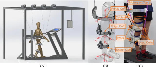
Fig. 1.1 shows the preliminary design of C-ALEX. The preliminary design of C-ALEX includes an overhead frame to support the motors, a treadmill for the user to walk on, and exoskeleton attached to the leg of the user. The exoskeleton mainly consists of three cuffs: the pelvic cuff, the thigh cuff and the shank cuff. No rigid link or joint is used
x0 z0 y0 x1 y1 z1 x2 y2 z2 IMUs Load Cells Pelvic Cuff Thigh Cuff Shank Cuff Cables Motors on Top ↑ (A) (B) (C)
Figure 1.1: The Preliminary Design of C-ALEX. (A) An overview of the preliminary design. (B) A closer view of the cuffs of the preliminary design with a local coordinate system for each segment of the leg. (C) C-ALEX attached to the leg of a user.
within the exoskeleton. The pelvic cuff is fixed to a height-adjustable external support frame. The thigh and the shank cuffs are tightly connected to the user’s thigh and shank, respectively. To create a secure connection between the thigh and shank cuffs and the leg, a layer of elastic band is first placed onto the user’s leg. An orthotics with velcro liners is then strapped on top of the elastic band. The cuffs are attached at the lateral side of the orthotics. The lateral distance between the cuff and the leg can be adjusted. To reduce the weight of the exoskeleton on subject’s leg, the thigh and shank cuffs are primarily made of 3D printed ABS plastic with sparse interior. The overall weight of the thigh and shank cuffs are 0.60kg and 0.54kg, respectively.
Four cables are used to actuate the exoskeleton. The cables are pre-stretched Nylon coated steel wires. All four cables are routed through the pelvic cuff. Two of these are attached to the thigh cuff, and the other two are routed through the thigh cuff and at-tached to the shank cuff. These four cables actuate two degrees-of-freedom of the user’s
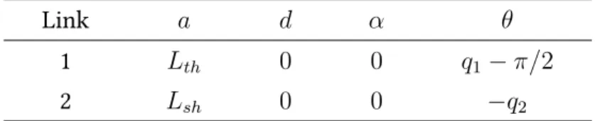
leg: the hip flexion/extension and the knee flexion/extension. The DH parameters of the exoskeleton are shown in Table 1.1. In the DH parameters, q1 is the hip flexion angle
and q2 is the knee flexion angle. Lth stands for thigh length, and Lsh stands for shank
length. These two parameters vary between individuals, and therefore need to be mea-sured and provided for each subject. The kinematics of C-ALEX are derived through the DH parameters and homogeneous transformations. All the cable routing points on the cuff have Teflon liners to reduce the friction between the cable and the cuff. The cable routing points are designed to be able to slide along the cuff to change the cable routing. Additional cable routing points can be added to accommodate extra cables to increase the controlled degrees-of-freedom.
Table 1.1: DH Parameters of the Preliminary Design
Link a d α θ
1 Lth 0 0 q1−π/2
2 Lsh 0 0 −q2
Lth: thigh length;Lsh: shank length.
Actuation and Control System
Each cable in the exoskeleton is driven by a AKM43 servo motor ¹ with custom made cable reels. The motors are supported by the overhead frame. The cable reels are used to help proper winding of the cables. The motors are powered by AKD servo drives ¹ operating in torque mode. A LSB200 load cell ² is connected to the end of each cable to measure the tension in the cable, with CSG110 signal conditioners ² to amplify the load
¹Kollmorgen, VA, US ²Futek, CA, US
cell signal. There is a VN-100 inertia measurement unit (IMU)¹ mounted on the thigh cuff and shank cuff to measure the hip and knee angle of the user during walking. A PXIe-8135 controller² is used for real-time control and data acquisition of the exoskeleton. The controlling software is developed in LabVIEW².
1.2 The Controller for Gait Assistance
The Dynamical Model of C-ALEX
The dynamic equations of motion of C-ALEX are derived through the Lagrangian method in Mathematica ³. As mentioned in Section 1.1, C-ALEX is modeled as a two-link serial chain in the sagittal plane of the leg as shown in Fig. 1.1. Based on this kinematic model, the dynamical equation of C-ALEX can be written in the following form:
D(q)¨q+C(q,q) ˙˙ q+G(q) =τc−τh, (1.1)
whereq = [q1, q2]T is the vector of joint angles withq1 and q2 represent the angles of
hip flexion and knee flexion, respectively;D(q)is the inertia matrix;C(q,q)˙ is the vector
of Coriolis and centripetal terms;G(q)is the vector of gravity terms;τcis the actuation
torques generated by the cables at each joint, andτhis the torques that C-ALEX applies to
the human user. TheD,C, andGterms on the left hand side of the equation are obtained
from the CAD model of C-ALEX and the measurements of the leg of the user.
¹VectorNav, TX, US
²National Instrument, TX, US ³Wolfram, IL, US
Equation (1.1) can be rewritten as:
τh =τc−(D(q)¨q+C(q,q) ˙˙ q+G(q)), (1.2)
which shows that the torque applied to the humanτh equals the actuation torqueτc
mi-nus the gravity G and dynamics D and C of the exoskeleton. Ideally, the user of the
exoskeleton should only receive the intended assistance without any disturbance due to the weight and inertia of the exoskeleton,i.e. :
τh =τa, (1.3)
whereτais the intended assistive torque to train the human user. As a result:
τc =τa+D(q)¨q+C(q,q) ˙˙ q+G(q), (1.4)
which shows that the exoskeleton should be able to compensate for its dynamics (D(q)¨q+ C(q,q) ˙˙ q) and gravity (G(q)) in addition to providing assistance in order to be fully
trans-parent. The gravity of the exoskeleton can be compensated easily as it only requires the knowledge of the joint angles q. The dynamics of the exoskeleton are harder to
com-pensate for as they involve joint velocityq˙and joint accelerationq¨, neither of which are
directly measured by C-ALEX. Walking is a highly dynamical motion, therefore q˙ and ¨
q cannot be simply ignored. If an exoskeleton has a large inertia, it will require a large
amount of torques to follow the motion of the leg. However, given the light-weight nature of C-ALEX, it does not require significant torques to move the cuffs on the leg, and
there-fore the dynamical terms in Eq. (1.2) were neglected. Then the torqueτcto be generated
by cables equals to:
τc=τa+G(q). (1.5)
C-ALEX uses an “Assist-As-Needed” control strategy to train the user to follow a pre-scribed ankle path. The exact method to generate the assistive torque τa is detailed in
Section 1.2, with some improvements introduced in Section 2.2. C-ALEX has a “transpar-ent” mode, in which case the exoskeleton does not provide any assistance to the user,i.e.
the assistive torqueτa = 0. Under this condition, the actuation torqueτconly
compen-sates for the gravity of the exoskeleton:
τc =G(q). (1.6)
Cable Tension Planning
In C-ALEX, the actuation torqueτcis generated by the four cables. The relationship
be-tween cable tensionT and actuation torqueτccan be found by:
JC(q)T =τc, (1.7)
whereT = [T1, T2, T3, T4]T represents the tensions in each cable. JC(q)is the Jacobian
matrix relation cable tension to joint torques. JC(q) can be found by the virtual work
principle as explained in the following paragraph.
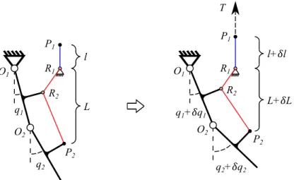
L+𝛿L l+𝛿l T q1+𝛿q1 q2+𝛿q2 L l q1 q2 P1 P1 P2 P2 R2 R1 R1 R2 O1 O2 O1 O2
Figure 1.2: A Schematic of a Two-link System Actuated by a Single Cable. One end of the cable is free (P1), while the other end of the cable is routed through pointR1andR2,
and fixed to the two-link system at pointP2. q1 and q2 represent the joint angles of the
two-link system;l denotes the length of the cable outside the two-link system (from P1
toR1);L denotes the length of the cable routed inside the two-link system (fromR1 to P2). ForceT pulls the cable at the free end (P1) and results in changes inq1,q2,landL.
schematic represents a simplified model of the cable-driven exoskeleton. One end of the cable is free while the other end of the cable is routed through a few routing points on the two-link system and attached to the distal link. Initially, the joint angles of the two-link system are q1 and q2, the length of the cable that is routed inside the two-link system
isL, and the length of the cable remains outside the two-link system is l. A forceT is
applied to the free end of the cable and causing a virtual displacement ofδl. As a result,
the configuration of the two-link system changes. The angles of the two joints change by
δq1andδq2, and the length of the cable routed inside the two-link system changed byδL.
Given that the total length of the cable (l+L) is constant, it is apparent that:
δL =−δl . (1.8)
the cable equals to the virtual work done by the generalized forces on the joints:
δW =T ·δl=τ ·δq , (1.9)
in whichτ = [τ1, τ2]T represents the generalized force,i.e. torques applied to the joints q= [q1, q2]T. We also have:
δl=−δL=−∂L
∂q δq . (1.10)
Substituting Eq. (1.10) into Eq. (1.9) gives:
τ =−(∂L ∂q)
T
T =JC(q)T T . (1.11)
Equation (1.11) shows that the Jacobian matrix relating the cable tensions to the joint torques can be found by the partial derivatives between the cable lengths and the joint angles. With four cables used in C-ALEX, the Jacobian matrixJC(q)in Eq. (1.7) is
JC(q) = −
∂(L1, L2, L3, L4) ∂(q1, q2)
, (1.12)
whereLiis the length of cableimeasured from the routing point on the pelvic cuff to the
final attachment point of the cable on the thigh or shank cuffs.
Equation (1.11) is of particular importance to the system as it provides the foundation to solve for the required cable tensions when some specific torques are desired at the joints. When torqueτcis required at the joints, cable tensionsT can be found by solving
the set of linear equations:
JC(q)T T =τc. (1.13)
Equation (1.13) is underdetermined as the number of cables is larger than the degrees-of-freedom of the system.
The range of tensions in the cables is limited. Since cables can only pull but not push, it is impossible for the tensions in the cables to be negative. In the actual system, due to the existence of friction along the cables, the minimum tension in a cable needs to be set above a positive value to keep the cable taut. Also, because the motors connected to the cables can only produce limited torque, there is a maximum limit on cable tensions as well. Therefore,T should satisfy:
T ∈[Tmin, Tmax]. (1.14)
In the case of C-ALEX, the cable tension range is set in between 7N and 70N.
Using Eq. (1.13) and Eq. (1.14) as constraints, an optimization problem can be formu-lated to find a proper set of cable tensions to generate desired torques. We use a quadratic objective function: f(T) = TT T for the optimization problem, which minimizes the
norm of cable tension vector. The advantage of using quadratic programming over linear programming is that the solution toT will change more continuously when the Jacobian
matrixJC(q)in the equality constraint Eq. (1.13) changes. This will help to avoid abrupt
cable tension changes when the leg moves from one configuration to another.
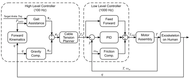
pro-Forward Kinematics Gait Assistance Gravity Comp.
Target Ankle Traj. Pankle + + + Cable Tension Planner Feed Forward Friction Comp. PID − ++ + Motor Assembly Exoskeleton on Human 𝝉G 𝝉a T T, ωm q ωm T q q
High Level Controller (100 Hz)
Low Level Controller (1000 Hz)
𝝉d Td Icmd
Figure 1.3: A Block Diagram of the Controller of C-ALEX.
gramming problem:
minf(T) =TT T
s.t. JC(q)T ·T =U and T ∈[Tmin, Tmax].
LabVIEW provides a quadratic programming solver that uses the active set method. This solver is used to solve the above problem in real time. The disadvantage of quadratic programming is that it is time consuming to solve. However, our controller is capable of solving the above problem at 100Hz without any delay.
The “Assist-as-needed” Controller
This exoskeleton is aimed at rehabilitation and therefore the controller uses an “assist-as-needed” strategy. The goal of the controller is to assist the ankle point of the user of the exoskeleton to move on a prescribed target path. The controller creates a tunnel-like force-field around the target path. If the end effector (ankle point) deviates from the target
path, the controller acts as a spring and pulls the end effector back to the target path. A two-level controller is implemented as shown in Fig. 1.3: A high level force-field controller that uses the position feedback of the exoskeleton to dictate the necessary cable tensions to create the force field, and a low level cable tension controller that controls the motors to produce the desired cable tensions using feedback from the load cells on the cables.
The high level force-field controller generates a force F at the ankle point that has
two components:
F =Fn+Ft. (1.15)
Fn is normal to the target path, and it will push the ankle point closer to the path. Ft
is tangential to the target path, pointing to the direction of movement, and it provides a gentle push to move the ankle point along the target path. The magnitude ofFn, Ft is
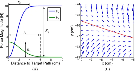
calculated as: ∥Fn∥=Kn·(1−e−( 2d rn)2) ∥Ft∥=Kt·e−( 2d rt) 2 , (1.16)
in whichKnandKtare the gains of the force field,dis the distance from the ankle point
to its nearest point on the target path. Equation (1.16) effectively creates two tunnels around the target path with diameters of rn and rt respectively. For the normal force Fn, the magnitude roughly equals toKnoutside the tunnel and gradually deceases to 0 N
inside the tunnel. For the tangential forceFt, the magnitude is 0 N outside the tunnel and
gradually increases to Kt inside the tunnel. Fig. 1.4 shows the change of Fn andFt as
a function of the normal distance from the target pathd, and a qualitative sketch of the
−10 −9 −8 −7 −6 −5 −79 −78 −77 −76 −75 −74 x (cm) y (cm) 0 2 4 6 8 10 0 2 4 6 8 10
Distance to Target Path (cm)
Force Magnitude (N) Fn Ft Kn rn rt Kt (A) (B)
Figure 1.4: Force Field Controller of C-ALEX. (A) The magnitude of the force field as a function of the normal distance to the target path. (B) A portion of the force field around a target path. The red line is the target path, and the blue arrows show the directions and magnitudes of the force field.
The force-field controller has two modes: the transparent mode and the assistive mode. The transparent mode is used for measuring the natural gait of the user. In the transparent mode, C-ALEX will only balance its own weight and will not provide any assistance to the user. The assistive mode is used for assisting the user to track the target ankle path. In the assistive mode, C-ALEX generates the aforementioned force field be-sides compensating for its own weight. The required joint torqueτcin the assistive mode
can be found by:
τc=Je(q)T F +G(q), (1.17)
whereF is the force-field force in Eq. (1.16) andJe(q)is the Jacobian matrix of the end
effector.
With the desired joint torqueτcobtained, the force-field controller uses the cable
cable and send it to the low level controller.
The low level controller includes three parts: A feed-forward part using the motor constant, a friction compensation part using the motor’s friction-speed model, and a close loop PID controller using the feedback from the load cells in the cables. Together, the low level controller is able to control the motors to generate tensions that closely follow the desired tensions calculated from the high level controller.
1.3 Evaluation on Healthy Subjects
An experiment was conducted to evaluate the performance of C-ALEX. The goal of the experiment was to verify that C-ALEX with the force field controller can assist the user to track a target ankle path different from his or her natural path. In the experiment, the subjects tracked a target ankle path with C-ALEX in both the assistive mode and the transparent mode. The hypothesis was that the subjects would have better path tracking performance in the assistive mode than in the transparent mode.
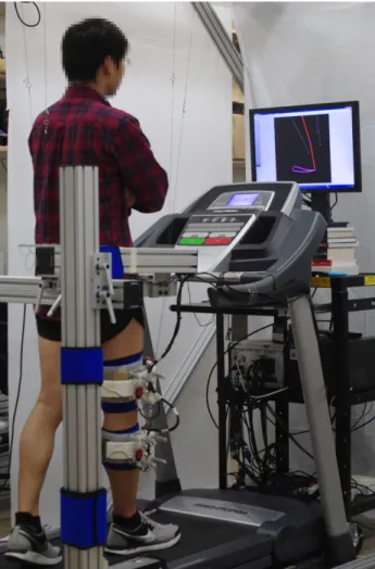
The setup of the experiment is shown in Fig. 1.5. Six healthy subjects participated in the experiment. The subjects were all male, aged between 20 and 35 years. Fig. 1.6 shows the protocol of the experiment. At the beginning of each experiment, C-ALEX was fitted onto the right leg of the subject, and then the experimenter took measurements of the length of the thigh and the shank of the subject as well as the locations of the cuffs. These measurements were provided to the controller. Each experiment was divided into 4 sessions: the familiarization session, the baseline session, the assistive (AS) session and the transparent (TR) session. Each session was 4 minutes long, and a 2 minutes break was
Figure 1.5: The Experimental Setup to Evaluate the Preliminary Design of C-ALEX. The subject was walking on a treadmill with C-ALEX attached to the leg. The screen placed in front of the subject was used to display the current pose of the leg and the target ankle path. Assistive Session 4 min Transparent Session 4 min Baseline Session 4 min Familiarization Session 4 min Break 2 min Break 2 min Break 2 min
Figure 1.6: The Experiment Protocol to Evaluate the Preliminary Design of C-ALEX.
given between each session.
The experiment started with the familiarization session, during which C-ALEX was put into the transparent mode. The subject was instructed to walk on a treadmill to get familiar with walking with C-ALEX. The speed of the treadmill was adjusted to the
com-fortable walking speed of the subject. Following the familiarization session was the base-line session, during which C-ALEX stayed in the transparent mode. The subject was instructed to walk naturally during this session. The natural gait pattern collected during this session was later used to generate the target ankle path in the AS and the TR sessions. The screen in front of the subject was turned off during the first two sessions.
During the baseline session, the hip and knee joint angles and the ankle path were recorded. Data during the first and the last minutes were discarded, and the remaining data were cut into gait cycles at the anterior most point of the ankle path and averaged across the gait cycles to obtain the averaged joint angles in a single gait cycle. The aver-aged joint angles were then reduced by 20% to create an ankle path that is both shorter and shallower than the baseline path. The top figure of Fig. 1.7 shows the baseline ankle path (black) and the modified ankle path (red) from a representative subject. This modified ankle path was then used as the target ankle path in the AS and the TR sessions.
During the AS and the TR sessions, the screen in front of the subject was turned on to display the current configuration of the leg and the target ankle path, as shown in Fig. 1.5. The subject was instructed to try to walk as closely to the target path as possible during these two sessions. During the AS session, C-ALEX was put into the assistive mode. The force-field gains in Eq. (1.15) were set asKn = 20, rn = 0.1, Kt = 3, rt = 0.05and were
consistent across all subjects. After AS session was the TR session, during which C-ALEX was put into the transparent mode. After the experiment, the joint angles and ankle path during each session were analyzed.
The ankle path during the AS and the TR sessions were recorded, cut and averaged in the same way as the ankle path during the baseline. The average ankle path during
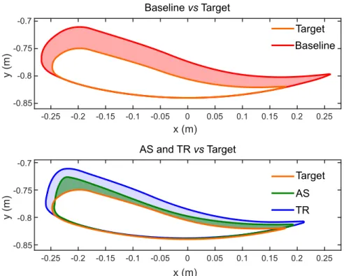
x (m) -0.25 -0.2 -0.15 -0.1 -0.05 0 0.05 0.1 0.15 0.2 0.25 y (m) -0.85 -0.8 -0.75 -0.7 AS and TR vs Target Target AS TR Baseline vs Target Target Baseline -0.85 -0.8 -0.75 -0.7 -0.25 -0.2 -0.15 -0.1 -0.05 0 0.05 0.1 0.15 0.2 0.25 y (m) x (m)
Figure 1.7: Ankle Path from a Representative Subject. The grey shaded area in the top figure is the deviation area between the baseline path and the target path. The blue and the green shaded areas in the bottom figure are the deviation area of the TR path and the deviation area of AS path, respectively.
the AS and the TR sessions of the same representative subject was plotted in the bottom figure of Fig. 1.7. It can be observed from the figure that the AS path is closer to the target path than the TR path, which demonstrates the effectiveness of the force-field controller of C-ALEX.
To quantify the effectiveness of C-ALEX, the normalized tracking error [61] of the AS path and the TR path was calculated and compared. Fig. 1.7 shows the deviation area of the baseline path (gray shaded area), the deviation area of the AS path (green shaded area) and the deviation area of the TR path (blue shaded area). The normalized tracking error of the AS (TR) path is calculated as the ratio between the deviation area of the AS (TR) path and the deviation area of the baseline path, i.e. the green (blue) shaded
0 0.5 1 * Normalized Deviation AS TR 1.5
Figure 1.8: The Normalized Tracking Errors of the AS and TR session. The error bars represent standard deviation. “∗” indicates significant difference atp <0.05level.
area divided by the grey shaded area. A smaller normalized tracking error suggests that the path closely overlaps the target path. Fig. 1.8 shows the normalized tracking error average across all subjects. The average normalized tracking error of the AS sessions is
0.493±0.421(mean±SD), and the average normalized tracking error of the TR sessions is 0.751±0.572(mean±SD). Wilcoxon signed rank test was used to compare the normalized
tracking error in AS sessions and in TR sessions. The result shows that the normalized tracking error in AS sessions is significantly smaller than that in TR sessions (p= 0.031).
This result validates our hypothesis that C-ALEX with force field can help the subject to follow a prescribed ankle path.
1.4 Conclusion
In conclusion, this chapter presented the preliminary design of the Cable-driven Active Leg EXoskeleton (C-ALEX) for human gait training. The exoskeleton is controlled by a force-field controller, which is able to assist the motion of the leg and help the ankle to
follow a desired path. An experiment with six subjects wearing C-ALEX was performed to validate the device and the controller. The results showed that the force-field controller is able to help the subject better track a prescribed ankle path.
Several limitations of the preliminary design of C-ALEX were identified: (i) the pelvic cuff of the exoskeleton is fixed to the ground, which restricts the pelvic motion of the user; (ii) the range of motion of the leg is limited by the cable routing; (iii) the current cable routing can only provide assistive force in the sagittal plane. These problems are rectified in the next design iteration of C-ALEX.
Chapter 2
An Improved Design of C-ALEX
After identifying the limitations of the preliminary design, an improved version of C-ALEX was designed and built. The cuffs of this new C-C-ALEX are completely redesigned to give the user more degrees-of-freedom and a greater range of motion. The controller has also several improvements to address the wrench feasible workspace limitation that is common in cable-driven robots.
2.1 Improvements in the Mechanical Design
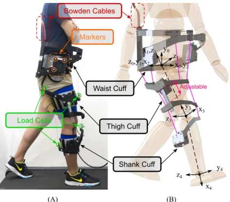
The new design of C-ALEX shares some similar cable-driven characteristics as the pre-vious preliminary design. Fig. 2.1 shows the CAD model of the new C-ALEX and the actual fabricated device worn by a user. The key feature of C-ALEX is its low weight. The cuffs of the new C-ALEX are redesigned to further reduce its weight. The cuffs are 3D printed with a sparse interior using ABS plastic, same as the preliminary design. The pelvic, thigh, and shank cuff weighs 2.7 kg, 1.0 kg and 0.6 kg, respectively. The pelvic cuff is largely stationary during walking, therefore the total moving weight of C-ALEX (thigh and shank cuff combined) is only 1.6 kg. The light-weight cuffs add minimal weight and inertia to the leg, thus create minimal disturbance to the gait of the wearer. Similar to the preliminary design, there are no mechanical links and joints to be attached to the human
Thigh Cuff
Shank Cuff
Waist Cuff Adjustable
Load Cells Bowden Cables Markers x0,y2 y0 z0,y1,x2 y3 x 3 z3 y4 x4 z4 x1,z2 z1 (A) (B)
Figure 2.1: Improved Design of C-ALEX. (A) C-ALEX attached to the leg of a subject. Load cells at the end of each cable are circled in green. Orange circles show the reflective markers on the pelvic cuff for motion tracking. More of these markers are placed on the thigh and shank cuffs as well. (B) A CAD model of the exoskeleton with local coordinate system of the kinematic model.
leg in this new design of C-ALEX. The joint-free design allows the leg of the wearer to move freely in all its natural degrees-of-freedom without any constraints. Besides keep-ing the lightweight and joint-free feature, the new C-ALEX has two major improvements over the preliminary design: (i) a redesigned cable routing that gives larger and more con-sistent maximum range of motion (RoM), and (ii) a new pelvic cuff with Bowden cables that allows constraint-free pelvic movement.
The maximum RoM of C-ALEX is limited by the distance between the cables and the human limb. If the distance is too small, cables may come in contact with the human body during motion. If the distance is too large, the design becomes bulky and cumbersome.
In this new C-ALEX design, we redesigned the cuffs and strategically routed the cables to achieve a large RoM that is sufficient for gait training while keeping a compact cuff profile. Besides being larger, the maximum RoM of this new design is also more consistent across wearers of different sizes. The thigh cuff of the new design is split into two pieces with adjustable distance. Through this adjustment, the cable routing across the knee joint is decoupled from the cable routing across the hip joint. Therefore, wearers of different leg lengths have a consistent cable routing across their joints, thus achieving a more uniform RoM. The RoM of the new C-ALEX is tested on human subjects, and the results are shown in Section 3.2.
Another major improvement of the new C-ALEX is the pelvic cuff. Studies have shown that restricting the pelvis motion during walking changes the kinematics and re-duces comfort [39], [44]. It is a challenging task to build an exoskeleton with mechanical linkages to include all the six degrees-of-freedom (DoF) motion of the pelvis. Using pas-sive DoF will require the wearer to take care of part of the inertia and/or weight of the exoskeleton, while using active DoF will drastically increase the complexity and cost of the whole system. In the preliminary C-ALEX design, the pelvic motion of the user was also restricted due to the externally supported stationary pelvic cuff. In this new design, the pelvic cuff is attached to the wearer. There is no external connection to the pelvic cuff other than the soft Bowden cables, therefore the wearer can enjoy the full six DoF motion of the pelvis with minimal constraints. Overall, the six DoF pelvic cuff together with the joint-free design creates a natural walking experience for the wearer without any restrictions to natural DoFs.
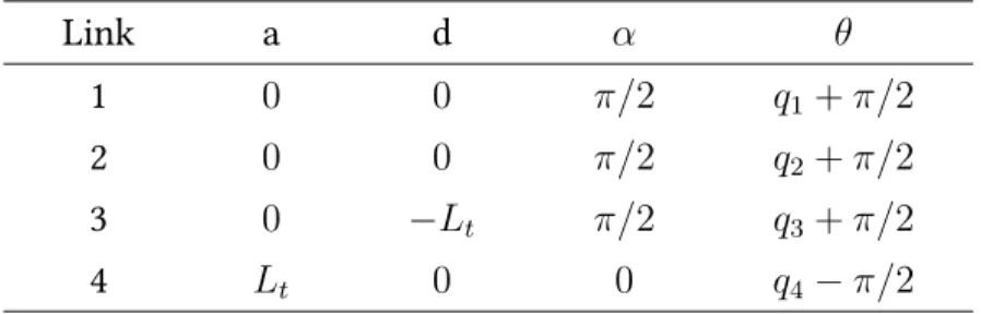
directly come down from the motors, Bowden cables are used to guide cables from the motors to the pelvic cuff to make the device appear less intrusive and more compact. After going through Bowden cables, bare cables are distributed around the pelvic cuff through a set of pulleys to minimize the friction. The cable routing from the pelvic cuff to the thigh and shank cuffs is shown in Fig. 2.1. Different from the preliminary design, the new C-ALEX is modeled as a four DoF two-link serial chain with a ball joint at the hip and a hinge joint at the knee. Fig. 2.1 shows the kinematic model of C-ALEX. The DH parameters of C-ALEX are shown in Table 2.1. Among the four DoF of C-ALEX, two are actuated by cables:q1hip flexion-extension andq4knee flexion-extension. The other two
DoF are passive. Same as the preliminary design, each cable of C-ALEX is driven by an AKM43 AC servo motor and the tension in each cable is measured by a Futek load cell at the end of the cable. The joint angles are measured by a Vicon ¹ optical motion capture system, which provides more accurate and reliable joint angle measurements than the IMUs used in the preliminary design. Reflective markers are attached to the pelvic, thigh and shank cuffs to allow optical tracking.
Table 2.1: DH Parameters of the Improved Design.
Link a d α θ
1 0 0 π/2 q1 +π/2
2 0 0 π/2 q2 +π/2
3 0 −Lt π/2 q3 +π/2
4 Lt 0 0 q4−π/2
Lt: thigh length;Ls: shank length.
In summary, the new C-ALEX inherits the main features of the cable-driven design:
the light-weight cuffs and the joint-free structure, and improves the RoM and gives com-plete DoF to the pelvic motion. Altogether, this new C-ALEX is an exoskeleton that adds minimal weight and inertia to the wearer with least constraint.
2.2 Improvements in the Controller
The Dynamical Model of the Improved C-ALEX
Different from the preliminary design, the new C-ALEX is modeled as a four DoF two-link serial chain instead of a two DoF double pendulum. The hip abduction/adduction as well as hip internal/external rotation DoF are also modeled in this new design. It is impossible to fully control all four DoFs with only four cables in C-ALEX, therefore, the controller only control the torque in two DoFs, the hip and knee flexion/extension DoF, same as the preliminary design. But this model can be used to calculate the un-intended torque applied to the un-controlled DoF. Except for the additional DoFs, other aspect of the dynamical model is similar to the preliminary design in Section 1.2. Based on this kinematic model, the dynamical equation of C-ALEX can be written as:
D(q)¨q+C(q,q) ˙˙ q+G(q) =τc−τh. (2.1)
whereq = [q1, q2, q3, q4]T is the vector of joint angles,D(q)is the inertia matrix,C(q,q)˙
is the vector of Coriolis and centripetal terms,G(q)is the vector of gravity terms,τcis the
actuation torques generated by the cables at each joint, andτhis the torques that C-ALEX
the subject. Given the light-weight nature of C-ALEX, the dynamical termsDandCare
neglected. Therefore, the actuation torquesτcequals to:
τc=τa+G(q). (2.2)
Under the transparent mode of C-ALEX, the the actuation torquesτcis:
τc =G(q). (2.3)
Improved Cable Tension Planning
After calculating the desired actuation torquesτc, the next step is to find a set of cable
ten-sions to produce the desired torque. As explained in Section 1.2, the relationship between the cable tensions and joint torques is formulated by the cable Jacobian matrix:
τd =J(q)T T . (2.4)
whereT = [T1, T2, T3, T4]T is the vector of cable tensions, andJ(q)is the cable Jacobian
matrix found by
J(q) =−∂(L1, L2, L3, L4) ∂(q1, q4)
, (2.5)
whereLiis the length of each cable measured from the pelvic cuff to the respective anchor
point. The cable tensionTihas to be kept between a minimum levelTminand a maximum
levelTmax,i.e.
The goal of the cable tension planner is to find a solutionT to Eq. (2.4) that is within
the limits of Eq. (2.6). In the preliminary design, this is solved by quadratic programming using Eq. (2.4) as an equality constraint:
minf(T) =TT T
s.t. JC(q)T T =U and T ∈[Tmin, Tmax].
(2.7)
This method works well if there is indeed a solution to Eq. (2.4) within the limits of Eq. (2.6). However, if C-ALEX is outside its wrench feasible workspace, i.e. there is no possi-ble solution ofT that can satisfies the constraint in Eq. (2.4), the quadratic programming
does not work. The controller of the preliminary C-ALEX mitigates this issue by using the solution of the last configuration in the wrench feasible workspace if C-ALEX goes outside the workspace. Then, once C-ALEX goes back to the wrench feasible workspace, a new solution to the Eq. (2.4) is found, which is generally different from the last avail-able solution. This causes a discontinuity in the cavail-able tension. Such discontinuities are undesirable as they will disrupt the gait of the wearer and cause instability to the cable tension controller. To solve this problem, new C-ALEX uses a different objective function for the quadratic programming problem:
minf(T) =τeTτe+µ TTT
s.t. Tmin ≤Ti ≤Tmax,
(2.8)
whereτe = J(q)T T −τd. This new objective function has two components: the first
componentµ TTT tries to minimize the sum of square of all tensions if multiple solutions
to Eq. (2.4) exist. µis a coefficient to adjust the relative importance of these two
com-ponents. Although this quadratic programming does not give a precise solution to Eq. (2.4), it guarantees that a solution can always be found across the RoM. Through careful adjustment ofµ, the error in Eq. (2.4) can be kept to a practically small level.
Improved “Assist-as-needed” Controller
The “assist-as-needed” controller used in Section 1.2 generates a force field around the target gait pattern. The assistance that the user receives is entirely based on the spatial movement of the leg. The temporal aspect of the gait was not taking into consideration by the controller. Essentially, the assistive force pushes the ankle towards a target point on the target ankle path that is closest to the current ankle position, but this target point may not be at the proper location for the ankle to be at this instance. For example, at a specific instance during walking, the user may be at the 75% of the gait cycle, but the closest point on the target ankle path might be at 85% of the gait cycle. This mismatch between the phase of the gait cycle of the user and the phase of the gait cycle of the target point might negatively affects the gait training result. Therefore, a new method to find the target point on the target ankle path is used in the new C-ALEX controller.
When a subject is walking with C-ALEX, the assistive controller finds the current ankle positionPankle by the joint anglesqusing the forward kinematics. The controller
also keeps a record of the ankle positions during the past three steps, and find an average ankle path (green path in Fig. 2.2 (A)). Let a pointP be the point on this average ankle
Phip Pknee ǁP'Pankleǁ (cm) 0 2 4 6 8 10 Magni tude (N) 0 2 4 6 8 10 Fn Ft τk τh x y P' (x%) Phip Pknee x y (A) (B) (C) Target Ankle Traj.
Average Ankle Traj. of Past 3 Steps P (x%) P' Fn F t Pankle Pankle
Figure 2.2: Improved “Assist-as-needed” Controller. The silhouette represents a walking subject. The purple lines are the kinematic model of the leg. Phip,Pknee andPankle
rep-resent the locations of the hip, knee and ankle joint. (A) Find the pointP on the average
ankle trajectory (green) the is closest toPankle, and then find the target ankle pointP′on
the target ankle trajectory (orange) with the same gait phase asP. (B) Find the direction
of the assistive force Fnand Ftto simulate at the ankle point. The equivalent torque of
the assistive forceτh andτkare generated by the cables at the hip and knee joint. (C) The
magnitude of the assistive forceFnandFtrelative to the distance betweenPankleandP′.
path that is closest to Pankle. Then, assuming that the ankle path of the current step is
very close to this averaged ankle path of past three steps, the phase of point P on the
average ankle path is a good estimation of the current phase of the gait. Using this phase, the controller finds the pointP′ on the target ankle path (orange path in Fig. 2.2(A)) at
the same phase, and simulates an assistive force to push the ankle towards P′. Similar
to the controller in the preliminary design, this assistive force has two components: a componentFnthat is pointing toP′, and a componentFtthat is parallel to the tangential
line atP′ on the target path, as shown in Fig. 2.2 (B). The magnitude of these two forces
are found in the same way as Eq. (1.16). Fig. 2.2 (C) shows how the magnitude of the two assistive forces changes asdincreases. The total assistive forceFa is the sum ofFnand Ft: Fa = Fn+Ft, and the assistive force controller simulates this virtual assistive force
Faby generating assistive torques at the hip and knee joints of the leg:
τa=Je(Fn+Ft). (2.9)
in which τa is the total assistive torque in Eq. (2.2) and Je is the Jacobian matrix that
relates the ankle velocity to the joint velocity. Then, the cable tension is calculated using the improved cable tension planner described in the previous subsection.
2.3 Conclusion
In conclusion, the new C-ALEX improved both its mechanical design and its controller. The newly designed cuffs of C-ALEX are light-weight, allow large RoM, and do not con-strain the DoF of the user. The improved controller of C-ALEX uses a new cable tension planner to remove discontinuity in tension generation and uses a new algorithm to pro-vide assistance based on the current phase of gait. This improved design of C-ALEX is used in the experiments detailed in the following chapters.
Chapter 3
Effects of Exoskeleton Weight and Inertia on Human Walking
Various leg exoskeletons have been designed for gait rehabilitation. The transparency of these exoskeletons is crucial to their effectiveness in gait training. The weight and inertia of an exoskeleton are two important factors affecting its transparency. The goal of this experiment is to investigate the effects of the weight and inertia of an exoskeleton on the natural walking of the subject. In this experiment, we added different levels of extra mass to C-ALEX to simulate heavier exoskeletons to study how the gait changes as exoskeleton weight and inertia change. By switching on and off the gravity compensation for the added mass, the effects of inertia can be isolated from the effects of weight.
3.1 Experiment Protocol
Twelve subjects (nine male and three female) participated in this experiment. The subjects were all healthy adults aged 22-31 with an average height of 177.2±7.5 cm and an aver-age weight of 71.1±8.0 kg (mean±sd). The experiment was approved by the Columbia University Institutional Review Board.
Each subject first performed a RoM test during which they flexed and extended their hip and knee joints to the maximum angle that C-ALEX allowed. Then, each subject completed an experiment protocol composed of eight sessions. Each session was 5 min
treadmill walking with one particular setup of C-ALEX. At the beginning of the protocol, the subject’s comfortable walking speed without C-ALEX or any added mass was deter-mined. That same speed was used in all eight sessions of the experiment. The average walking speed of the subjects was 0.99±0.06 m/s (mean±sd).
The eight walking sessions were divided into three groups based on the setup of C-ALEX as shown in Table 3.1
(1) Free-walking group (FW): It includes three sessions with three levels of added mass: +0kg (no added mass), +1.8kg and +3.6kg. The added mass was divided evenly and attached to the thigh and shank of the subjects. The thigh and shank cuffs and all the cables of C-ALEX were removed during these sessions. This setup allowed the subjects to walk naturally without any interference from C-ALEX.
(2) C-ALEX no compensation group (NC): It includes three sessions with the same three levels of added mass as the FW group (+0kg, +1.8kg, and +3.6kg). Subjects were wearing C-ALEX in the transparent mode during these sessions, i.e. C-ALEX did not provide any assistance other than compensating for its own weight.
(3) C-ALEX weight compensation group (WC): It includes two sessions with +1.8kg and +3.6kg of added mass. In these sessions, C-ALEX compensates not only the weight of itself, but also the weight of the added mass.
The order of the C-ALEX setups and the weight conditions under each setup was randomized among subjects.
During the experiment, the hip and knee flexion-extension angles and ankle position relative to the hip was recorded by C-ALEX at 100Hz. Within each 5 min session, the first 180 seconds were considered as adaptation period. The data from the 180 s to the 270 s
Table 3.1: Experiment Conditions to Study the Effect of Weight and Inertia.
Groups Sessions
Free-walking (FW) FW+0kg FW+1.8kg FW+3.6kg
C-ALEX No Comp. (NC) NC+0kg NC+1.8kg NC+3.6kg
C-ALEX Wt. Comp. (WC) N/A WC+1.8kg WC+3.6kg
Eight experiment sessions divided into three groups. The two boxes show the two sep-arate repeated-measure ANOVAs used in the data analysis.
were used for data processing.
The performance of the C-ALEX controller was evaluated using the RMS torque errors during each session. The torque errorτerr is the difference between the desired torqueτd
and the actual torque generated by cable:
τerr=τd−J(q)T Tactual, (3.1)
whereJ(q)is the cable Jacobian andTactualis the actual cable tension measured by load
cells.
The gait kinematics data were divided into gait cycles at heel strike and then aver-aged into a single gait cycle. Four variables were used to evaluate the changes in gait kinematics: hip flexion-extension RoM (hip RoM), maximum knee flexion, step length and step height. Two separate repeated-measure analysis of variance (rmANOVA) were used to compare each kinematics measurements across the sessions. The first rmANOVA is a 3×2 design that compares the three sessions in the FW group with the three sessions in the NC group (red box in Table 3.1). This comparison shows the effect of C-ALEX itself and the combined effect of the weight and inertia of the added mass. The second
rmANOVA is a 2×2 design that compares the two sessions in the WC group with the two weighted sessions (+1.8kg and +3.6kg) in the NC group (blue box in Table 3.1). Through compensating the weight of the added mass, the effect of inertia on gait can be isolated. This comparison reveals how weight and inertia independently affect the gait the subjects.
3.2 Experiment Results
Range-of-Motion Test
Table 3.2 shows the RoM of C-ALEX compared with the RoM during the unloaded free walking (FW+0kg). The result shows that the RoM of C-ALEX is adequate for the natural walking of the subjects. No subject reported their gait being constrained by C-ALEX during the whole experiment.
Table 3.2: Range of Motion of C-ALEX in Degrees.
Hip Flexion Hip Extension Knee Flexion
Inside C-ALEX ᵃ 43.8±7.4 11.6±1.8 84.3±7.6
Natural Walking ᵇ 31.2±3.7 8.1±1.9 68.0±6.3
ᵃ Maximum angle (mean±std) reachable inside C-ALEX ᵇ RoM (mean±std) during natural walking outside C-ALEX
Controller Performance
Fig. 3.1 shows the RMS torque tracking error averaged across the subjects during the five sessions with C-ALEX attached. This error includes both the error from low-level PID controller and the error from the approximation in cable tension planner (2.8). The magnitude of the RMS torque error was similar under each experiment condition, and
NC+0kg NC+1.8kg NC+3.6kg WC+1.8kg WC+3.6kg 0
1 2 3
RMS Torque Tracking Error (Nm)
Hip Knee
Figure 3.1: The Average RMS Torque Tracking Error during the Experiment. The vertical bars represent standard deviation.
0 50 100 -10 0 10 20 30 40 50 60
70 (A) Joint Angles: FW vs NC
FW+0kg NC+0kg FW+3.6kg NC+3.6kg Hip Flexion Knee Flexion 0 Hip Flexion Knee Flexion 50 100 -10 0 10 20 30 40 50 60 70 (B) Joint Angles: NC vs WC WC+3.6kg NC+3.6kg
Figure 3.2: Hip and Knee Joint Angle of a Gait Cycle during Selected Sessions.
the small standard deviation bar suggests that the controller performance was consistent across all subjects.
Gait Kinematics
The joint angle trajectories averaged across the subjects during selected sessions are shown in Fig. 3.2. Fig. 3.3 shows the four kinematic variables in all sessions averaged among subjects. The rmANOVA between the FW and NC sessions shows that wearing
FW NC WC * * * * *
(A) Hip Flexion RoM (deg) (B) Knee Max Flexion (deg)
(C) Step Length (cm) (D) Step Height (cm)
+0kg +1.8kg +3.6kg +0kg +1.8kg +3.6kg +0kg +1.8kg +3.6kg +0kg +1.8kg +3.6kg 42 40 38 36 70 68 66 64 18 17 16 15 66 64 62 60 58
Figure 3.3: Averaged Kinematic Results from the Experiment. The vertical bars indicate the standard error. “∗” indicates significance at0.05level.
C-ALEX significantly increased the hip RoM (p = 0.004) and step length (p = 0.006) of
the subject. Meanwhile, increasing the added mass significantly increased the step length (p <0.001) and significantly reduced max knee flexion (p= 0.010). The step height also
reduced with added mass, but not significantly (p= 0.074).
The rmANOVA between the NC and WC sessions showed that compensating the weight of the added mass significantly increased hip RoM (p = 0.043) and max knee
flexion (p= 0.004), while step height increased but not significantly (p= 0.082). An
in-teraction between the effect of weight compensation and the effect of added mass is found in hip RoM. Post-hoc analysis within each level of added mass showed significant effect of weight compensation at +3.6kg level (p= 0.004), but not at +1.8kg level (p= 0.589).
3.3 Discussion
Effect of C-ALEX
Even though C-ALEX has minimal weight and inertia and virtually no kinematic con-straint, it still caused an increase in the hip RoM and the step length. The inertia of C-ALEX itself as well as the torque tracking error shown in Fig. 3.1 could be the main factor causing this change. C-ALEX has a torque tracking error of around 2Nm at the
hip and1Nm at the knee, which is comparable to the result in [42]. Other factors causing
the change in kinematics include possible inaccuracies in the measurement of the size of the subject and the locations of the cuffs. All these factors are consistent across the experiment conditions for the same subject, therefore they should not affect the analysis of the added weight and inertia. Overall, compared with free walking (FW+0kg), walking with C-ALEX (NC+0kg) increased the hip RoM by1.08◦ and step length by1.36cm on
average. The changes are relatively small compared with the results in [40], [62], showing that C-ALEX can better preserve the natural gait. It is also worth noting that C-ALEX can still benefit from more sophisticated controllers such as in [42], [63] to further improve its transparency, while it is a bigger challenge for a heavy exoskeleton to reduce its weight and inertia.
Effect of Added Mass
Increasing the level of added mass in FW and NC sessions affects all the gait variables except for the hip RoM. This proves our hypothesis that the changes in the gait of the subjects increase as the amount of added mass increase. The increase in step length due to
the added mass implies a similar increase in stride time and a decrease in cadence, giv