Estimating an articulated tool’s kinematics via
visuo-tactile based robotic interactive manipulation
Qiang Li, Andre ¨
Uckermann, Robert Haschke, and Helge Ritter
Abstract— The usage of articulated tools for autonomous robots is still a challenging task. One of the difficulties is to automatically estimate the tool’s kinematics model. This model cannot be obtained from a single passive observation, because some information, such as a rotation axis (hinge), can only be detected when the tool is being used. Inspired by a baby using its hands while playing with an articulated toy, we employ a dual arm robotic setup and propose an interactive manipulation strategy based on visual-tactile servoing to estimate the tool’s kinematics model.
In our proposed method, one hand is holding the tool’s handle stably, and the other arm equipped with tactile finger flips the movable part of the articulated tool. An innovative visuo-tactile servoing controller is introduced to implement the flipping task by integrating the vision and tactile feed-back in a compact control loop. In order to deal with the temporary invisibility of the movable part in camera, a data fusion method which integrates the visual measurement of the movable part and the fingertip’s motion trajectory is used to optimally estimate the orientation of the tool’s movable part. The important tool’s kinematic parameters are estimated by geometric calculations while the movable part is flipped by the finger.
We evaluate our method by flipping a pivoting cleaning head (flap) of a wiper and estimating the wiper’s kinematic parameters. We demonstrate that the flap of the wiper is flipped robustly, even the flap is shortly invisible. The orientation of the flap is tracked well compared to the ground truth data. The kinematic parameters of the wiper are estimated correctly.
I. INTRODUCTION
Robots can largely extend their manipulation capability by using tools, e.g. using a brush to clean a shoe, using a wiper to clean the car’s window and using a vacuum cleaner to clean a room. The well established research lines to using a tool in robotics domain are from two aspects. (1) Exploring the affordance of the tool. In this direction, researchers were studying the relation between the tool’s behaviors and manipulation results [18] [23] [28] [21]. (2) Integrating the tools with the robot as a new manipulator such that the robot can control the tool easily. [24] [9] [7] [19]. In neuroscience, this phenomenon is called the body-tool assimilation or body schema extension [5].
There are two main approaches to study how to inte-grate a tool with the robot (1) geometry-based method and (2) experience-based learning method. For geometry-based method, the task of the robot is to automatically estimate the kinematic parameters of the tool [10] [13]. Given predefined motion patterns to move the grasped tool, the robot will The authors are with the Neuroinformatics Group / CITEC, Bielefeld University, Germany. {qli,aueckerm,rhaschke,helge} @techfak.uni-bielefeld.de
use its vision or other modality to observe the relation between its end-effector and the tool’s coordinate frame to derive the tool’s kinematic parameters. After the tool’s kinematics model is developed, it will be integrated with the robot’s kinematics to form a new kinematic chain, which can be used to control the tool easily like it is a part of the robot. The experience-based learning method is a data driven learning procedure in which the geometry knowledge of the robot and the tool is not explicitly modeled but learned by imitation [15] or exploration [25] manipulation. For imitating to use a tool, the robot is guided to use the tool by kinesthetic teaching. The arm’s moving trajectory is recorded and learned, then generalized to implement a similar but not previously experienced manipulation using DMP (Dynamic Movement Primitives) or other machine learning method [15]. For exploration manipulation, the robot will explore the relation between its joints and the tool’s visual features by developing a probability graph or neural network model while the grasped tool is randomly moved in free space [25]. This paper will focus on modeling the tool with the robot as a new manipulator and employing geometry-based method to estimate parameters. It is a simple and practical method to estimate the kinematic model of a grasped tool. The paper is organized as follows. In Sec.II, we introduce the state of the art for tool’s usage in robotics domain. In Sec.III-A, we propose a visuo-tactile servoing controller which can be used to deliberately generate interact behavior to estimate the tool’s kinematic parameters using the method in Sec.III-B. In Sec.IV, a detailed experiment and discussion are given to evaluate the feasibility of the proposed method. Finally in Sec.V, we summarize the current results and discuss future work.
II. STATE OF THE ART
Tool usage is an important skill towards improving the manipulation capability of a robot. Teaching the robot to automatically and dexterously use a tool is still a challenging task. Inspired by Iriki et al.’s neuroscientific findings [16] that a tool is assimilated to monkey’s body at the neuronal level of the brain, lots of researchers were using neural networks to model the tool’s usage as a plastic extension process of the robot’s body schema. In [19], Nabeshima et al. proposed a visuo-tactile associative memory network to let the robot autonomously learn a reach and touch task in 2D space by randomly moving a grasped stick. After 60 seconds, the robot is aware of the existence of the tool and learned the tool’s parameter (length of a stick). Using the Deep learning method, Takahshi. et al. [27] [26] dealt with a T-shaped tool.
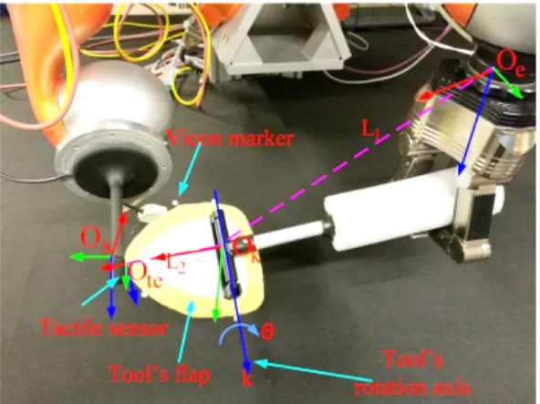
Fig. 1: Experimental setup. One arm with a robotic hand holds an articulated tool and the other arm equipped with tactile fingertip flips a flap of the tool. The related coordinate frame Ok–tool’s internal frame, Ote–tool’s effector frame,
Os fingertip sensor frame, Oe, robot effector frame. The needed tool’s kinematics chain parameters are k, L1, L2
andθ
The authors did not manually design the robot’s internal model and the tool’s visual features, but autonomously learn it from robot’s joints angle and tool’s raw images using a deep neural network. So the robot and tool’s model were learned together. It is not necessary to learn the robot’s model again when a new tool is given to this robot.
The work [19] [27] [26] handles only tools with simple geometrical shapes. In real world, however, a tool normally has a complex shape. To this end, Kemp et al. [9] observed many robotic usable tools and argued that controlling the tools’ endpoint is the most important factor for many ap-plications. They proposed an optical-flow based method to estimate the relative position between the endpoint of an unknown tool and the robot’s end-effector. The manipulation of these tools are discussed in [10] by considering the tool’s endpoint as the new end-effector of the robot. For tools which can not be simplified and modeled as an endpoint, a tool’s coordinate frame should be defined in order to combine the tool as a new link of the robot’s kinematic chain. Using this strategy, St¨uckler and Behnke [24] developed many vision-based applications for everyday tools. Li et al. [13] estimated the coordinate frame of a tactile tool by tactile-interaction. Combining the estimated coordinate frame with the robot’s kinematic model, the robot was able to use the tool for tactile servoing.
Except for rigid tools, there are lots of articulated tools which have one or more internal DOF (degree of freedom). Typically some DOFs (e.g. rotation axes) are hidden and can not be directly visually observed. Only when the tool is interacting with the external environment, the rotation axis can be localized by indirect computation. These tools can be modeled as a new kinematic chain [8] [25] [17] [2]. Sturm et al. [25] used a probabilistic graphical model to represent an articulated object. Their method learned not only the kinematic parameters, but also the number of object’s DOF.
However, the method required a complete homogeneous transformation between the object’s parts, which is very difficult to obtain without attaching markers on the object.
Katz and Brock [8] exploited RGB-D image processing to estimate an articulated tool’s kinematic parameters. Their method, however, only works in 2D because a simple sweep action is used to interact with the object while it is placed on the table. Mart´ın and Brock [17] proposed to use texture information and probabilistic recursive state estimation to improve the perception of an articulated object. The authors claimed that the pose of object’s movable part can be esti-mated and used in the robot’s control loop. We are working with a similar scenario – using a robot finger to interact with a grasped articulated tool (Fig. 1) and use the robot’s action to improve the robustness of estimation. The kinematic chain of the tool is represented byTk
e andTktewhich are the
homogeneous transformations from robot’s end-effectorOe to the tool’s internal frame Ok and the tool’s end-effector frameOte. Both transformations can be computed from the estimated parameters: rotation axisk, translation vectorsL1,
L2 and rotation angleθ.
Our main contributions are:
1) We propose a visuo-tactile servoing controller to ro-bustly flip the flap of the tool. The kinematic parameters (k,L1,L2 andθ) of the tool are estimated during the
course of flipping.
2) We propose a data fusion method which fuses the robot motion and the observed visual motion of the flap to improve the estimation accuracy of the flap’s pose (θ). It also can predict the flap’s pose if it is not observable for the camera.
Compared to the work of Mart´ın and Brock [17], this work (1) includes and exploits the robot’s action to model the articulated tool and (2) uses depth information instead of texture of the articulated tool, which is less sensitive to lighting conditions and (3) tracks the moved flap even it is not visible by RGB-D camera.
III. INTERACTION-BASED CONTROL AND PERCEPTION In our experiment, we are using a tool that has a flat surface, mounted with a hinge to a handle that the robot holds in the hand. All involved coordinate frames and the experimental setup are shown in Fig. 1 (subscripts denoting the world frame (w), the end-effector frame (e), the tactile sensor frame (s), the tool’s end-effector frame te and the tool’s internal frame k). The three-fingered Schunk hand stably grasps the tool’s handle, such that we can assume that there is no relative motion between the tool’s handle and the hand. We design a visuo-tactile servoing controller, detailed in Sec. III-A, to deliberately control the fingertip to flip the tool’s flap. It is not a trivial task to flip the flap and simultaneously maintain the contact point. BecauseL2
is unknown, we can not offline plan the fingertip movement for the flipping task. This only can be done by exploiting the vision and tactile feedback to generate the fingertip’s motion online. In our case, the fingertip is given a feedforward command in its sensor frame Os, and its translation and
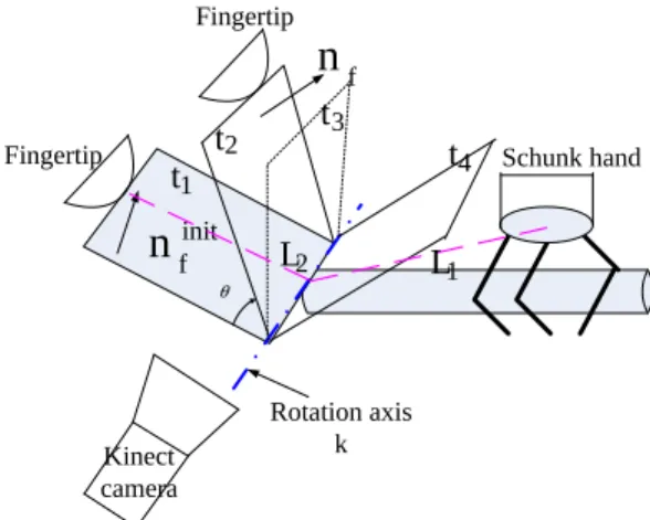
θ Fingertip Fingertip Rotation axis k
n
finitn
f 1 2 3 4 Kinect camerat
t
t
t
Schunk hand 1L
2L
Fig. 2: Visuo-tactile servoing controller guarantees that the fingertip remains in contact with the flap through the exce-cution of the task. t1 is the time to start the flipping. k is
the rotation axis and computed as the intersection line of the flap’s surface at different times ti. From t3 tot4 the flap is
not visible by the camera.
rotation will be adapted by a visuo-tactile servoing controller to maintain the contact.
The parameters (L1,L2,kandθ) are estimated during the
course of flipping motion from the observed trajectory. The flipping procedure is shown in Fig. 2.kis the tool’s rotation axis. It can be estimated by computing the intersection line of the flap’s surface at different time instants because the rotation axis is not changed while the flap is flipped.θis the flap’s rotation angle. Given the noisy RGB-D measurement, the angle value is estimated using a Kalman filter. L2 is a
vector which starts from fingertip’s contact point to a shortest distance point on rotation axiskandL1is a vector from the
arm’s end-effector to the this shortest distance point.
A. Visuo-tactile servoing controller
Many applications have been studied to use vision and tactile feedback, e.g. for door opening [20] [22], grasping [4], object exploration [12] and in-hand manipulation [6]. All these studies have shown that tactile sensors are very important in order to successfully implement different ma-nipulation tasks. Almost all previous work considered planar tactile sensor arrays, and tactile features were computed using image processing methods. In this paper, we propose an innovative method to use a 3D-shaped tactile fingertip [11] (see Fig. 4) in the visuo-tactile servoing control framework, which poses some extra challenges compared to our previous work [14]. The overall controller structure is illustrated in Fig. 3 and will be explained in the following subsections. We firstly introduce the new tactile servoing controller in Sec. III-A.1 and subsequently focus on the visual-servoing branch in Sec. III-A.2.
1) Fingertip tactile servoing controller: The tactile ser-voing control cycle (in the bottom part of Fig. 3) aims at maintaining the desired contact position and contact force on the fingertip via sliding and rolling motions. If a deviation from the desired position/force is detected, the fingertip will
reactively move to reduce this deviation. To this end, the vector ∆f(t) = [∆xs,∆zs,∆fx,∆fy,∆fz,∆α] of tactile-feature errors (position error of the contact blob centroid,
[∆xs,∆zs], Fig 4; 3D contact force error,[∆fx,∆fy,∆fz]; and angular error,∆α) is first fed into a PID-type controller to obtain a control vectoru:
u=kPt·∆f(t) +kIt·
Z
∆f(t)dt+kDt·(∆f(t)−∆f(t−1))
As the tactile sensor cells measure normal forces only, we can estimate the 3D contact force from the force-weighted surface normalsni at all activated taxel locations:
[fx, fy, fz]t= m X i=1 fini n= f kfk
where fi is the normal force magnitude measured by the
i-th taxel and ni is the corresponding surface normal. Each component of the PID-filtered tactile feature error is subsequently mapped onto an error-reducing motion twist
Vtact
s expressed in the sensor frame utilizing a fixed,
task-independent, inverted sensor JacobianJs−1:
Vtacts =Js−1·u Js−1= 1 0 1 0 0 0 0 0 0 1 0 0 0 1 0 0 1 0 0 1 0 0 0 0 0 0 0 0 0 1 −1 0 0 0 0 0 (1)
The particular form of Js−1 arises from the contact ge-ometry: positional deviations are compensated by sliding motions along the same axes in the tangential (x-z) plane of the sensor. However, a deviation along the x-axis can also be compensated by a rotation about the z-axis through the contact point. The orientation of a contact edge on the sensor can be adjusted by rotation about the y axis of the sensor frame. Normal force errors are corrected by a translational motion along thex, y, z-axis.
This basic scheme is augmented with a task-dependent
projector matrixPtactthat selects task-relevantmotion com-ponents. Usually, Ptact is a simple 6×6 diagonal matrix, where ones and zeros are used to toggle individual twist com-ponents on and off. For example, if contact position control is desired, one will choosePtact= diag(1,0,1,0,0,0). When additionally force control is required, the second diagonal entry is also set to one. The 4th and6th entries will enable
rolling, and the5th entry will enable twisting.
Finally, the twists from the tactile feedback loop are fed into the low-level inverse kinematics module of the control basis framework. To this end, the twistVsexpressed in terms of the sensor frameOs will be transformed into the world frame Ow employing the adjoint matrix derived from the current forward kinematicsTsw=Tew·Tse= (Rws,pws):
AdTws = Rws pˆwsRws 0 Rws (2) Comparing with the previously proposed tactile-servoing control method [14], this new approach exploits the known
PID −1 s
J
Ad
Tws Instant Inverse Kinematics Robot Interaction dq
Tactile Feature -tact sV
vis sV
wV
Task-Oriented VisualServo Algorithm
Visual Servo
Tactile Servo
visP
tactP
ff sV
q
f
tgtactf
tgvisf
tact∆
CBF
[
]
T z y x s sz
f
f
f
x
α
f
ffTool’s flap tracker
Task Planner
[
θ
]
fn
1
s
Fig. 3: Visuo-tactile servoing controller
Fig. 4: Left: distribution of 12 taxels on the curved fingertip surface. Right: activation of 4 taxels and estimated contact position (small red cube) and normal direction (red arrow).
CAD model of the 3D-shaped sensor to estimate 3D forces and contact locations and thus enable tactile servoing with curved sensor surface.
2) Visual-servoing controller: While the tactile-servoing controller allows the fingertip to blindly establish, optimize, and maintain contact during manipulation, other motion commands can be superimposed e.g. to start the interaction task, or to incorporate visual feedback to ensure robust object interaction. We illustrate this manipulation mode with an example shown in Fig. 3. In order to flip the flap, the fingertip will start moving with a feedforward command ff f along the x axis in the Os frame. The desired force is along the normal direction of the contact point. In order to improve the robustness of flipping, the fingertip should actively roll such that the normal directionnf of the flap surface is orthogonal
to the surface normalnat the contact point. To this end, we are using a flap tracker to estimate the normal direction of the flap’s surface, and the visual servoing algorithm, illustrated in Fig. 3, computes the twist motionVviss of the fingertip as
Vsvis= [vviss = 0,wsvis], wviss =kPv·R
s
w·(n×nf) (3)
wherekPv is a diagonal matrix which is used to tune the
rotation rates.Rs
w transforms the rotation vector of the twist motion from the world frame to the sensor frame.
Fig. 5: The segmentation of the tool’s handle and the pivoting cleaning head using surface normal histograms of RGB-D camera point cloud data [30]. left: The surface normal directions of the point cloud data of the cleaning head and the handle were not segmented due to normals being similar. right:A successful segmentation of the cleaning head and the handle because of the surface normal direction difference of the tool parts exceeding a threshold
Finally, the obtained contact twist can be masked (again using a task-specific projector matrixPvis) and added to the tactile motion component to yield an overall twistVs.
B. Flap tracking and kinematic parameter estimation
To estimate the surface normal of the tool’s flap, we propose a simple surface tracker. Firstly, using ROI and robot self-filtering [29], the obtained point cloud is reduced to the tool’s point cloud. Subsequently, we cluster the normal directions of the remaining point cloud to segment the tool into two parts (flap and handle) using normal histograms introduced in [30]. These histograms represent the global distribution of surface normals by mapping the x- and
y-components of all normals into a 2D histogram composed of11×11bins. If the surfaces of the handle and the flap are initially parallel, only a single histogram bin will be activated (Fig. 5 left). However, during the course of flipping, the activation will split across two bins / blobs as two different clusters of normal directions will emerge (Fig. 5 right).
This split already emerges for small angles. To segment the tool’s point cloud, we identify the two distinct clusters in the histogram and back-project them to the point cloud. Points whose normals cannot be associated to either of the clusters will be dropped. The mean normal direction serves as the resultant normalnf.
As soon as the angle between the flap’s normal and the camera’s view direction approaches 90 degree, the flap will become invisible for the RGB-D camera. In order to cope with this, we also predict the flap’s normal direction from the performed robot motion using Rodrigues formula:
nf =nf0cos(θ) + (k×nf0)sin(θ) +k(k·nf0)(1−cos(θ))
wherenfis the predicted andnf0the initial normal direction.
k is the rotation axis determined via intersection of flap planes at different time instants [3, p. 305]. Because the flap’s plane equation is rather sensitive to the noise of the point cloud, we smoothly filter the rotation axis k over a specified time window. The rotation angleθis estimated with the following Kalman equations:
¯
θ(t) = ˆθ(t−1) + ˙θ (4)
ˆ
θ(t) = ¯θ(t) +w(θm(t)−θ¯(t)) (5) wherew is a manually tuned gain to update the prediction
¯
θ using the measured value θm from the camera and θ˙ is the angular velocity of the flap movement which follows equations:
vcp=L2×k·θ˙ θ˙=
|vcp| |L2|
(6) Here, |vcp| is the linear velocity of the contact point, estimated from a smoothly filtered contact position deviation. The other two kinematic parameters L1 and L2 are easily
computed if k is estimated correctly. Given the fingertip’s contact point and the arm’s end-effector position, L2 points
from the fingertip’s contact point to the shortest-distance point on the rotation axis k and L1 is a vector from the
end-effector to this shortest-distance point. IV. EXPERIMENTAL EVALUATION
A. Experiment Setup
The whole robotic flipping setup is shown in the Fig. 1. It is composed of two Kuka LWRs, which have mounted a Schunk dexterous hand on one arm and a tactile fingertip on the other one. A calibrated Kinect camera is placed in front of it. The robot’s kinematics is known, which also includes the position and normals of taxels on the 3D-shaped fingertip. To obtain ground-truth data for evaluation, we use a marker-based Vicon tracking system.
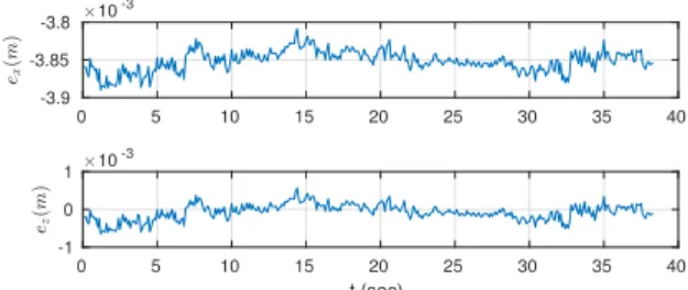
0 5 10 15 20 25 30 35 40 -3.9 -3.85 -3.8 10 -3 0 5 10 15 20 25 30 35 40 t (sec) -1 0 1 10 -3
Fig. 6: Contact position error in the sensor frame
0 10 20 30 40 50 60 70 80 t (sec) -0.05 0 0.05 0.1
Fig. 7: Dot product between the normal direction of the flap and the normal direction of contact point. The fingertip actively rolls in order to decrease this value until 0.
The manipulation process splits into three phases: (1) pre-contact, (2) establishing and maintaining pre-contact, (3) actual flipping. In the first phase, the fingertip is manually moved close to the tool’s flap, such that the second phase can be easily implemented with a tactile servoing controller, approaching the flap to establish and maintain the desired contact force of 0.5N. After having established the contact, the contact point on the fingertip is controlled to lie at the center of taxels 0, 3, 8 and 11 (see Fig. 4) using corrective rolling motions of the tactile controller.
The thirst phase is initiated by providing a feed-forward commandfff to move the fingertip along thex-axis ofO
s. During the course of flipping, the tactile servoing controller will compensate for deviations from the desired contact force and contact point’s position. After the tool is segmented into two parts, the flap’s normal direction is determined and tracked. The visual servoing controller will actively control fingertip rolling according to Eq. 3. The whole flipping process is shown in the accompanying video [1]. A quantitive evaluation is provided in the following two subsections.
B. Actively flip the flap of an articulated tool
First we evaluate the visuo-tactile controller’s ability to maintain the desired contact position and orientation. Fig. 6 shows the position error of the contact point, which only exhibits small oscillations (¡ 1mm) during the course of flip-ping. However, there is a rather fixed deviation of 4mm from the desired contact point (mainly along the x-axis), which is intentionally not corrected for because a sliding motion along thex-axis and a rotation about the sensor’sz-axis are conflicting with the motion to flip the flap determined by the visual-servoing controller. Consequently, the projection
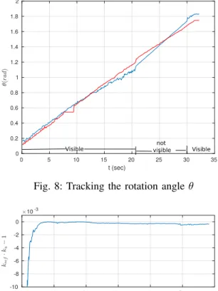
0 5 10 15 20 25 30 35 t (sec) 0 0.2 0.4 0.6 0.8 1 1.2 1.4 1.6 1.8 2
Visible notvisible Visible
Fig. 8: Tracking the rotation angleθ
0 10 20 30 40 50 60 t (sec) -10 -8 -6 -4 -2 0 10-3
Fig. 9: Estimation of the estimated rotation axis k in com-parison to its ground truth value kref.
matrix was chosen to bePtact= diag(0,0,1,1,0,0). Fig. 7 shows the evolution of the dot product between the estimated flap’s normal directionnf and the surface normal
n at the contact point, which should be zero in order to successfully flip the flap. Because the flap is initially not detected, the dot product of the two vectors is rather large in the beginning. However, after the flap was correctly detected, the visual servoing controller will move the fingertip (Eq. 3) and gradually reduce the error within the first 8s of the motion. From time 50s to 55s, there is a peak caused by the invisibility of the flap in the camera. Notice, that the arm moves very slow intentionally.
C. Flap tracking and kinematics estimation
To evaluate correct tracking of the tool’s rotation angleθ, we employ ground-truth information obtained from a Vicon tracking system, which provides 1mm positioning accuracy. Fig. 8 illustrates that the rotation angle is well tracked also during a phase when the flap becomes invisible to the camera (time 21s – 30s). During that phase, the Kalman filter essentially predicts a linear evolution of θ according to the robot’s motion. There are also some phases of larger errors (t=16..21s andt=30..31s), which is due to a strongly reduced number of points in the flap’s point cloud resulting in a larger error of the estimated normal direction.
The tool’s kinematics parameters are evaluated in Figs. 9 to 11. Fig. 9 shows that the direction of the axis is perfectly estimated after about 7s of motion, which corresponds to
0 5 10 15 20 25 0 0.02 0.04 0.06 0 5 10 15 20 25 -0.05 0 0.05 0 5 10 15 20 25 t (sec) -0.04 -0.02 0 0.02
Fig. 10: The estimated position error of L1
0 5 10 15 20 25
-0.05 0 0.05
Fig. 11: The estimated position error ofL2. Only deviation
inxaxis is shown because deviations iny andz are zero.
roughly30◦. To this end, we plotted the scalar product ofk
with its ground-truth valuekref, which should become equal
to one when both direction coincide.
Comparing with the ground truth, the estimated, component-wise errors ofL1 andL2 are shown in Figs. 10
and 11. The mean errors are about 1-2 cm for both vectors after convergence. The estimation accuracy ofL1andL2is
directly determined by the shortest-distance point onkfrom the contact location. Hence, they are indirectly affected by the estimation of the rotation axis, which has two compo-nents: the rotation axis k and a support point on that axis. As shown in Fig. 9, the direction vector k is estimated accurately. Hence, we can conclude that the error ofL1and
L2 mainly originates from an error in the estimation of the
support point.
V. CONCLUSIONS AND FUTURE WORK We introduced an interaction-based method to estimate the kinematic parameters of an articulated tool with a flap. Our method uses a visuo-tactile controller to implement the interactive manipulation of the tool using a dual arm robotic setup. One arm, equipped with a robotic hand, grasps the tool’s handle and the other arm, equipped with a tactile sensitive fingertip, flips the flap of the tool. During active interaction, the shape of the tool is changed and the detailed kinematic parameters of the tool are estimated in an online fashion using geometrical calculations.
When the tool’s model is unknown to the system, the interactive manipulation cannot be planned offline. Instead
the motion must be generated online employing the pro-prioception, vision and tactile feedback. The visuo-tactile servoing controller is exploiting the advantage of the comple-mentary modalities to improve the robustness of interaction: the tactile for maintaining the contact position and the vision for rolling the fingertip in order to guarantee that the normal direction of the contact point is orthogonal to the normal direction of the flap. The controller needs robust feedback of the flap’s normal direction, which, however, is not available when the tool’s flap is not visible for the camera. To this end, a data fusion method (Kalman filter) combining the vision and the fingertip’s motion trajectory is used to optimize the estimation of the flap’s normal direction.
The robot experiment demonstrated the robustness of our proposed method and the kinematic parameters of the articulated tool are estimated correctly. Plans are afoot to integrate the parameters of the learned tool with the robot’s kinematic model to implement manipulation tasks with the tool, e.g. cleaning a table.
ACKNOWLEDGMENT
This work was funded by DFG’s SPP priority program “Autonomous Learning” (SPP 1527-1).
REFERENCES
[1] https://www.youtube.com/watch?v=gzzaz0ltebs&feature=youtu.be. Accessed: 2018-07-25.
[2] Cristina Garcia Cifuentes, Jan Issac, Manuel W¨uthrich, Stefan Schaal, and Jeannette Bohg. Probabilistic articulated real-time tracking for robot manipulation. IEEE Robotics and Automation Letters (RA-L), 2(2):577–584, April 2017.
[3] Andrew S Glassner.Graphics gems. Elsevier, 2013.
[4] Robert Haschke. Grasping and manipulation of unknown objects based on visual and tactile feedback. InMotion and Operation Planning of Robotic Systems, pages 91–109. Springer, 2015.
[5] Matej Hoffmann, Hugo Marques, Alejandro Arieta, Hidenobu Sum-ioka, Max Lungarella, and Rolf Pfeifer. Body schema in robotics: a review. IEEE Transactions on Autonomous Mental Development, 2(4):304–324, 2010.
[6] Carlos A Jara, Jorge Pomares, Francisco A Candelas, and Fernando Torres. Control framework for dexterous manipulation using dynamic visual servoing and tactile sensors’ feedback. Sensors, 14(1):1787– 1804, 2014.
[7] Yiannis Karayiannidis, Christian Smith, Francisco E Vina, and Danica Kragic. Online contact point estimation for uncalibrated tool use. In
Robotics and Automation (ICRA), 2014 IEEE International Conference on, pages 2488–2494. IEEE, 2014.
[8] Dov Katz and Oliver Brock. Extracting planar kinematic models using interactive perception. InUnifying Perspectives in Computational and Robot Vision, pages 11–23. Springer, 2008.
[9] Charles C Kemp and Aaron Edsinger. Visual tool tip detection and position estimation for robotic manipulation of unknown human tools.
Computer Science and Artificial Intelligence Laboratory Technical Report, 83, 2005.
[10] Charles C Kemp and Aaron Edsinger. Robot manipulation of human tools: Autonomous detection and control of task relevant features. In
Proc. of the Fifth Intl. Conference on Development and Learning, 2006.
[11] Risto Koiva, Matthias Zenker, Carsten Sch¨urmann, Robert Haschke, and Helge J Ritter. A highly sensitive 3d-shaped tactile sensor. In
Advanced Intelligent Mechatronics (AIM), 2013 IEEE/ASME Interna-tional Conference on, pages 1084–1089. IEEE, 2013.
[12] Qiang Li, Robert Haschke, and Helge Ritter. A visuo-tactile control framework for manipulation and exploration of unknown objects. In
Humanoid Robots (Humanoids), 2015 IEEE-RAS 15th International Conference on, pages 610–615. IEEE, 2015.
[13] Qiang Li, Robert Haschke, and Helge Ritter. Learning a tool’s ho-mogeneous transformation by tactile-based interaction. InHumanoid Robots (Humanoids), 2016 IEEE-RAS 16th International Conference on, pages 416–421. IEEE, 2016.
[14] Qiang Li, Carsten Sch¨urmann, Robert Haschke, and Helge Ritter. A control framework for tactile servoing. InProc. RSS, 2013. [15] Wenbin Li and Mario Fritz. Teaching robots the use of human tools
from demonstration with non-dexterous end-effectors. In Humanoid Robots (Humanoids), 2015 IEEE-RAS 15th International Conference on, pages 547–553. IEEE, 2015.
[16] Angelo Maravita and Atsushi Iriki. Tools for the body (schema).
Trends in cognitive sciences, 8(2):79–86, 2004.
[17] Roberto Mart´ın Mart´ın and Oliver Brock. Online interactive perception of articulated objects with multi-level recursive estimation based on task-specific priors. InIntelligent Robots and Systems (IROS 2014), 2014 IEEE/RSJ International Conference on, pages 2494–2501. IEEE, 2014.
[18] Austin Myers, Ching L Teo, Cornelia Ferm¨uller, and Yiannis Aloi-monos. Affordance detection of tool parts from geometric features. In
Robotics and Automation (ICRA), 2015 IEEE International Conference on, pages 1374–1381. IEEE, 2015.
[19] Cota Nabeshima, Yasuo Kuniyoshi, and Max Lungarella. Adaptive body schema for robotic tool-use. Advanced Robotics, 20(10):1105– 1126, 2006.
[20] Mario Prats, Pedro J Sanz, and Angel P Del Pobil. Vision-tactile-force integration and robot physical interaction. InRobotics and Automation, 2009. ICRA’09. IEEE International Conference on, pages 3975–3980. IEEE, 2009.
[21] Ashutosh Saxena, Justin Driemeyer, and Andrew Y Ng. Robotic grasping of novel objects using vision. The International Journal of Robotics Research, 27(2):157–173, 2008.
[22] Andreas J Schmid, Nicolas Gorges, Dirk Goger, and Heinz Worn. Opening a door with a humanoid robot using multi-sensory tactile feedback. In Robotics and Automation, 2008. ICRA 2008. IEEE International Conference on, pages 285–291. IEEE, 2008.
[23] Alexander Stoytchev.Robot tool behavior: A developmental approach to autonomous tool use. Georgia Institute of Technology, 2007. [24] J¨org St¨uckler and Sven Behnke. Adaptive tool-use strategies for
anthropomorphic service robots. InHumanoid Robots (Humanoids), 2014 14th IEEE-RAS International Conference on, pages 755–760. IEEE, 2014.
[25] J¨urgen Sturm, Cyrill Stachniss, and Wolfram Burgard. A probabilis-tic framework for learning kinemaprobabilis-tic models of arprobabilis-ticulated objects.
Journal of Artificial Intelligence Research, 41:477–526, 2011. [26] Kuniyuki Takahashi, Tetsuya Ogata, Hadi Tjandra, Yuki Yamaguchi,
and Shigeki Sugano. Tool-body assimilation model based on body babbling and neurodynamical system. Mathematical Problems in Engineering, 2015, 2015.
[27] Kuniyuki Takahshi, Tetsuya Ogata, Hadi Tjandra, Yuki Yamaguchi, Yuki Suga, and Shigeki Sugano. Tool-body assimilation model using a neuro-dynamical system for acquiring representation of tool function and motion. In Advanced Intelligent Mechatronics (AIM), 2014 IEEE/ASME International Conference on, pages 1255–1260. IEEE, 2014.
[28] V Tikhanoff, U Pattacini, L Natale, and G Metta. Exploring affor-dances and tool use on the icub. InHumanoid Robots (Humanoids), 2013 13th IEEE-RAS International Conference on, pages 130–137. IEEE, 2013.
[29] Lukas Twardon. http://www.iclcv.org/tutorials/pointcloud-filtering.html. Accessed: 2018-01-20.
[30] Andre ¨Uckermann, Robert Haschke, and Helge Ritter. Realtime 3d segmentation for human-robot interaction. InIntelligent Robots and Systems (IROS), 2013 IEEE/RSJ International Conference on, pages 2136–2143. IEEE, 2013.
![Fig. 5: The segmentation of the tool’s handle and the pivoting cleaning head using surface normal histograms of RGB-D camera point cloud data [30]](https://thumb-us.123doks.com/thumbv2/123dok_us/768246.2597162/4.918.481.822.407.676/segmentation-handle-pivoting-cleaning-surface-normal-histograms-camera.webp)