Toward Rapid Manufacturability Analysis Tools for
Engineering Design Education
Roby Lynn
1, Christopher Saldana
1, Thomas Kurfess
1, Nithin Reddy
2,
Timothy Simpson
2, Kathryn Jablokow
2, Tommy Tucker
3, Saish Tedia
4,
Christopher Williams
41Georgia Institute of Technology, Atlanta, GA 2Pennsylvania State University, State College, PA
3Tucker Innovations, Inc., Charlotte, NC
4Virginia Polytechnic Institute and State University, Blacksburg, VA [email protected], [email protected], [email protected], [email protected], [email protected], [email protected], [email protected],
[email protected], [email protected]
Abstract
Engineering students are often unaware of manufacturing challenges that are introduced during the design process. Students will sometimes design parts that are either very difficult or impossible to manufacture, because they are unaware of the intricacies and limitations of various manufacturing processes. Design for manufacturability (DFM) education must be improved to address these issues, and this work is a vision for implementation of a rapid method for facilitating DFM education in terms of subtractive and additive manufacturing processes. The goal is to teach students about how their designs impact ease and cost of manufacturing, in addition to giving them knowledge and intuition to fluidly move between both additive and subtractive manufacturing mindsets. This work describes use of a commercial high-performance computing (HPC)-accelerated parallelized trajectory planning software package called SculptPrint, which enables students to visualize the subtractive manufacturability of the parts they design. While SculptPrint is currently limited to subtractive manufacturability analysis, this work also describes the future development of a manufacturability analysis tool for Additive Manufacturing (AM). Analysis is performed on a set of sample parts for both subtractive and additive manufacturing. The results demonstrate the effectiveness of advanced manufacturability tools in manufacturing process selection with consideration of manufacturing time, cost, and complexity. A distributed architecture is also examined that will allow students to perform manufacturability analysis without physical access to HPC hardware.
Keywords: GPGPU, High Performance Computing, Design for Manufacturability, Computer-Aided Manufacturing, Additive Manufacturing, Subtractive Manufacturing, Manufacturability Education, Manufacturability Analysis, Distributed Cybermanufacturing
Volume 5, 2016, Pages 1183–1196
44th Proceedings of the North American Manufacturing Research Institution of SME http://www.sme.org/namrc
1 Introduction
Subtractive manufacturing (SM) is a classical idea that has been evolving for a long time. It is responsible for a large number of parts that are manufactured in the United States and the rest of the world. SM has many advantages over AM, including the ability to shape a variety of materials and the superior surface finish and uniform mechanical properties (strength, elastic modulus, etc.) of the finished part. However, SM can be challenging and requires substantial experience to use effectively. While the rise of CNC (Computer Numerical Control) machine tools has enabled greatly increased part complexity and manufacturing speed, skilled operators are still required in order to use these platforms. The most significant hurdle in the implementation of these machines by novice students, aside from cost, is the difficulty of the required machine programming. This programming is usually accomplished using a computer-aided manufacturing (CAM) package, which creates G-Code to run the machine; CAM is powerful, but it still requires machining experience to fully understand and implement. As a result, the use of CNC machine tools by students for the manufacture of complex parts is very difficult and not commonly taught in typical engineering programs.
Instead, students tend to seek more user-friendly additive manufacturing (AM) processes for producing prototype parts, such as fused deposition modeling (FDM) for plastics and Direct Metal Laser Sintering (DMLS) for metals (Geraedts et al., 2012). AM is the process of building a 3D object in a layer-by-layer fashion. Each successive layer of material is fused with the preceding layer by the application of thermal energy, binders, or curing agents. A variety of AM technologies are currently available for different types of polymers, metals, alloys, composites, ceramics and resins (Frazier, 2014, Wong and Hernandez, 2012), and these AM processes allow easy and convenient creation of complex geometries without extensive manufacturing experience (Anderson, 2012, Gibson et al., 2010, Lipson and Kurman, 2013, Flowers and Moniz, 2002). Unlike SM, AM does not require the use of jigs, fixtures, complex tooling, extensive human interaction, or coolants (Huang et al., 2013). However, this ease of making parts often comes at the expense of additional build time and cost. AM is not always economical, and machining a part can often be less expensive (3vUMDQDQG3HWURúDQX), yet many students have turned to AM as the preferred option for making parts, no matter how simple they are. Since traditional SM is dominant in industry, it is important for students to not undermine conventional manufacturing if they are to become effective manufacturing engineers. Additionally, students need to recognize that AM is not always the best process for realizing their designs in terms of product quality, cost, and manufacturing time; while it is the best option in some cases, subtractive processes are more valuable in other scenarios. Students need to be trained in both AM and SM processes; this will enable them to think about both types of processes and ensure that they have the ability to seamlessly and completely leverage the two across the design spectrum.
This paper describes a framework for use in engineering design education that will provide students with a better and more rigorous understanding of both traditional subtractive manufacturing and additive manufacturing. It promotes the thought processes of students to consider both AM and SM processes, along with combinations thereof. Additionally, this framework gives students added insight into implementation details of these manufacturing processes; it is a first step towards an educational experience that integrates both additive and subtractive manufacturing into the design and build process. DFM principles are well known and can be best taught using a hands-on approach (Bralla, 1999). Students must be comfortable in both the AM and SM realms; thus, Georgia Tech (GT), Virginia Tech (VT), and Penn State University (PSU) have combined their experience in AM and SM processes to provide analysis tools usable in both arenas. The result leverages a software package, SculptPrint, which was developed jointly between GT and Tucker Innovations for rapid manufacturability analysis, visualization, and G-Code creation. SculptPrint removes challenges present in traditional CAM and allows students to rapidly see their designs from concept to production. It also allows for easy design changes and modifications. This work also emphasizes the need for manufacturability analysis for AM.
Students can leverage these manufacturability analysis tools to design parts compatible with AM or SM and exploit the unique strengths of both types of processes.
2 Background
SculptPrint: Manufacturability analysis software for SM
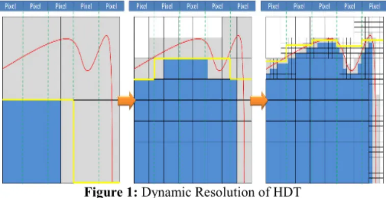
SculptPrint is a commercial software application that allows for a high degree of automation in the production of G-Code for CNC machines. SculptPrint takes an input model and converts it to a compressed, voxelized representation of the part, which enables rapid analysis on parallel computing platforms (Carter et al., 2008, Tarbutton et al., 2013, Tarbutton et al., 2010). A modified binary tree, called a hybrid dynamic tree (HDT), is constructed from the part model and provides a fully digital representation of the part. The HDT allows for efficient compression, because its resolution changes throughout the model and is increased only when necessary to define the part surface (Hossain et al.,
2015). Figure 1 shows the change in resolution as the HDT is built along a part surface. The HDT is suitable for processing on a parallelized platform where analytical models are unsuitable. High-performance GPUs (graphical processing units), which are readily available to consumers and commercial customers alike, provide the parallel computing platform (Konobrytskyi, 2013). These GPUs are present in many standard computers, and can be leveraged to perform computations. This allows for rapid, automated G-Code generation for parts that are quite complex and would normally take hours to program. Work is ongoing in the area of automated process planning for NC machining, which can be used to further automate G-Code generation (Turley et al., 2014). Figure 2 presents an example
Figure 2:Machining Simulation for a Complex Part
part that demonstrates the machining simulation provided by SculptPrint on a part that would normally be considered a candidate for an AM process. DFM guidelines are well known; Manufacturability Assessment Systems (MASs) for machining have been studied at great length, and multi-process analysis systems are in development. However, it is most valuable to teach students about the limitations of these processes individually, rather than allow them to rely on software to do it automatically (Kim, 2015, Shukor and Axinte, 2009). The overall geometric capabilities for additive manufacturing are generally greater than those afforded by subtractive manufacturing due to the fact that the shaping of the part is completed in a bottom-up fashion wherein material and/or energy is selectively added to a substrate (Williams et al., 2011). Because of its layer-wise approach to fabrication, geometric path planning for additive manufacturing is more straightforward than in the case of subtractive manufacturing, and several open-source software programs exist for slicing and generating toolpaths for extrusion printers (Slic3r, Repetier, KISSlicer, ReplicatiorG, 3DSlicer).
Manufacturability analysis for AM
While there are significantly fewer constraints imposed on geometry in AM as compared to SM, there still exist geometric features that are difficult to manufacture via AM. Defining these constraints and providing design guidelines is still a significant need in AM research (Rosen, 2014). While an AM build is relatively easy to begin (e.g., toolpath creation is automated), other important aspects of additive processes must be mapped and considered during the design process, including material compatibility, quality limitations (e.g., surface roughness, tolerances), and interactions between build geometry and process parameters (e.g., orientation of layers and thus anisotropy, presence of support structures, and surface area of each layer; if the surface area is too large, it can cause layer warping and delamination).
For evaluating manufacturability of the part using AM, the following factors need to be considered: 1) Build volume: The build volume gives an estimate of the amount of material required to manufacture the part, and in turn, material cost per part. Also, in some machines, there is a restriction on the maximum volume of the part that can be manufactured.
2) Minimum feature size: Even though AM is capable of producing intricate parts with complex geometries, there are limitations on the minimum size of features that can be produced. The type of AM process and resolution of the machine being used limits the minimum feature size of a part. In addition, high-aspect ratio features (e.g., thin walls) can be so fragile as to not be able to survive post-processing; hence, a minimum wall thickness has to be maintained to provide sufficient strength to the part.
3) Volume of Support material: In AM, each layer has to be supported by the preceding layer in order to successfully manufacture the part. Depending upon the AM process and machine, certain features require support material to be manufactured, such as some surfaces, overhangs, negative drafts, and undercuts that are at an angle (measured between normal and horizontal) which is less than a critical value. Such features should be avoided wherever possible, as using supports increases the build time and the cost of manufacturing. Such features might also require post-processing to remove support material, which could affect the quality of the part.
4) Build time: Build time largely depends upon layer thickness and Z-height of the part. AM techniques are in general comparatively slower than SM, as they build the part layer-by-layer, and hence, build times have to be optimized. Also, some processes require significant preparation time before the build starts (such as powder bed heating in a powder bed fusion process) or delay between depositing two successive layers, which also needs to be taken under consideration.
5) Estimation of surface roughness: For various applications of AM products, surface roughness is an importance factor, as aesthetics of the product mainly depend upon surface roughness. Various factors affect surface roughness, such as layer thickness, contact area, amount of support material, etc. While an exact calculation might not be easy, factors affecting surface roughness could be optimized to improve surface roughness of a given part.
6) Build Orientation: All the factors discussed above from 1-5 depend upon the orientation of the part with respect to the machine axis. The optimum orientation of the part depends upon its intended
use, functionality, and the priorities of the individual building the part. For example, if build time is of utmost importance to the user, then the optimum orientation of the part would be one which has minimum height in the Z-direction relative to the machine axis (although the optimum orientation of a given part using minimum Z-height might not be the same as the optimum orientation with minimum number of support structures). The user should consider all possible orientation scenarios with respect to each factor and select the best according to his/her priority.
Ideally, these DFM considerations could be integrated and automated into CAD software to assist a designer in creating a manufacturable product. However, calculating all the above-mentioned factors using a polygonal model (usually STL format) is non-trivial. Yong, et al. have proposed a computational method based on offsetting operations for manufacturability analysis of polygonal models based on minimum feature size (Yong and Xiaoshu, 2010). While this technique might be effective, it is computationally intensive and not automated. As such, commercially-available Design for Additive Manufacturing software (e.g., Magics for direct-metal AM and Stratasys Insight for FDM) are limited to support generation, build-time estimation, and other pre-processing steps (Munguía et al., 2008).
The current work is based on the assumption that a voxel-based representation of geometry significantly simplifies the manufacturability analysis. Such a representation effectively allows one to represent a part geometry as a three-dimensional two-bit array (voxel on/off), which greatly simplifies DFM analyses. For example, a minimum feature size analysis can be quickly conducted by simply checking that the number of coincident voxels in a layer exceeds a pre-defined lower constraint that matches the resolution of the deposition tool. For the purposes of this study, commercial packages such as Magics and Insight are used to emphasize the need for design for additive manufacturing education.
3 Results
Subtractive Manufacturability Analysis
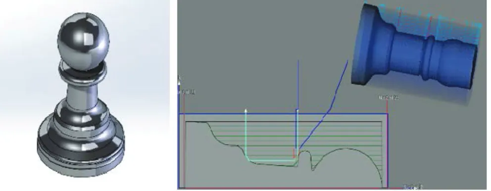
For students to be comfortable with SM, they must be aware of the two main groups of machining processes that exist: turning and milling. A trial application of the new framework described here was carried out at Georgia Tech in early 2016, beginning with these SM processes. The trial began by assessing students’ knowledge of machining processes, followed by an introductory lecture on machine tool configurations and tooling. Next, SculptPrint was used to provide a visualization of a simple 2-axis turning operation on a sample part, as shown in Figure 3. The tool that was defined to cut this part is a
standard 35° diamond insert turning tool, and it is evident from the SculptPrint analysis that the undercut below the head of the pawn will be unreachable with this tool. Additionally, the 0.8 mm nose radius of
the tool limits the sharpness of internal corners that can be reached. The basics of machine operation were reviewed (buttons, G-Codes, etc.), and each student machined an individual part.
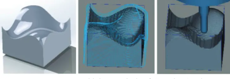
SculptPrint also allows for milling analysis that can demonstrate to students the machining limitations imposed by a standard 3-axis machining center. The blue points in Figure 4 are areas that are
inaccessible by a tool when this example part is fixtured in the vise of a 3-axis machine. For this example, only cutting with the tip of a ball endmill was allowed; therefore, SculptPrint considers the side milling of the walls of the center hole to be impossible. While some of these inaccessible points could be reached using a machine tool with more than three axes, the goal is to demonstrate the limitations of each machine configuration to the students. The part shown in Figure 5 demonstrates the
machining analysis and toolpath generation performed on a 3-dimensional surface that is possible to create with a 3-axis milling machine.
SculptPrint can also be used for functional parts, such as those that undergraduates would create for introductory build courses. In Georgia Tech’s ME2110 sophomore-level design class, students are tasked with creating an autonomous machine that will perform a range of duties. For this machine, the students have most frequently employed FDM machines in Georgia Tech’s Invention Studio to create their parts, such as the pulley example in Figure 6. Many of the students in ME2110 are only comfortable
Figure 5:Machining Analysis of Complex 3-axis
Figure 6:Functional Parts Made with AM and SM Figure 4:3-axis Machining Center Simulation
with printing the part, although in this case, machining takes much less time and produces a better result. Thus, a second session of the pilot test of the new framework introduced SculptPrint training for the part in Figure 6, followed by a review of machine operation and machining of the part. If the students had ways to employ CNC machine tools that are as straightforward as those used in AM, they would be able to distinguish the scenarios in which each process is best. To assess which is best, several criteria need to be considered, such as part material (limited for AM according to process used), maximum part size (limited for AM), part complexity (AM can handle highly complex parts), desired surface finish (AM parts might need post processing to get desired surface finish), part quantity (CNC is more cost effective for large quantities), and repeatability (CNC is much more repeatable than AM in general). However, many of the drawbacks of AM as compared with SM are disregarded due to the ease with which a part can be printed (no concern for starting stock, no need to purchase tooling, etc.).
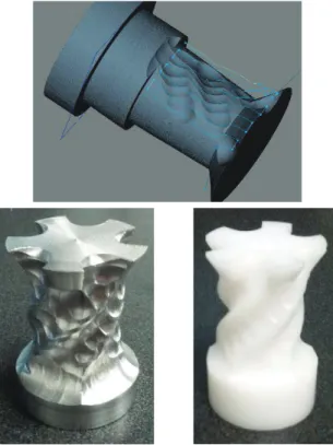
SculptPrint has also allowed for the creation of more complex geometries using CNC machine tools that would normally require an experienced CAM operator hours to program. Figure 7 shows the
progression from part model to plastic and aluminum parts for 4-axis geometry. In a matter of weeks, a student with little experience on 4- and 5-axis machine tools was able to create complex parts using only SculptPrint. While the plastic part is suitable for an AM process, the metallic version is better to be machined, because access to metal AM equipment is much less common than access to a machine tool.
Additive Manufacturability Analysis
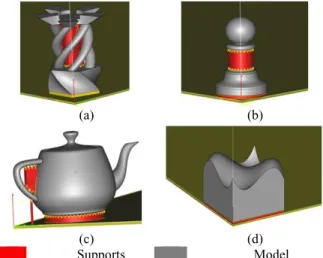
The trial application at Georgia Tech of the new integrated framework focused only on SM; preparations for a similar trial based on AM are underway, as described here in a discussion of the key concepts and issues that must be covered in this educational component. In general, two types of AM processes – polymer-based fused deposition modeling (FDM) and metal based direct metal laser sintering (DMLS) – are used in design education for projects and prototypes. The sample parts shown in Figure 8 were analyzed for manufacturability using FDM and DMLS processes to facilitate machine
and material selection by the user (student). For this study, analysis was primarily focused on build time, support generation, and amount of material. Surfaces with an orientation angle between normal and horizontal less than a certain value require support structures. For example, this limiting value for an EOS machine is 25º(EOS). Such rules are not identical for both FDM and DMLS processes. Also, build
times and material required vary between these two processes. Similarly, each process has specific rules for minimum feature size, length of overhangs, minimum gaps, wall thickness, etc.
With these rules and guidelines established, a single process cannot be determined as omni-competent. Individually, there are process specific advantages and disadvantages in terms of cost, time and material. Figures 8 and 9 show the required support structures for manufacturing using FDM and
(a) (b)
(c) (d)
Supports Model
Figure 9:Required Support Structures for Manufacturing Using a DMLS Process
(a) (b)
(c) (d)
Supports Model
DMLS processes, respectively. Clearly, support structures are not required for surfaces at an orientation greater than a specific angle. Figures 8(a) and 8(c) show complex surfaces which can be built without requiring support structures. Clearly, support structures for FDM are required in large number compared to that of DMLS process. This gives a hint that threshold of length of overhangs and surface orientation is less in FDM than DMLS process. Figures 8 (a), (c) and 9(a), (c) emphasize the difference in regions where support structures are required for FDM and DMLS processes. However, support generation cannot be the sole criterion for selecting a suitable AM process. The model of the teapot in Figure 9(c) contains trapped powder material inside the cavities and open spaces. Thus, the laser-based powder bed process is not suitable for manufacturing geometries with these types of cavities. This specific part requires multiple post-processing steps to remove trapped powder and also interior support structures. An FDM process can be used to manufacture this model and the internal support structures can be removed within a single post-processing step.
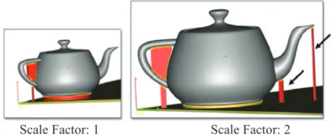
The length scale of the model is also important when predicting the surfaces which require support generation. The model of the teapot was magnified by a factor of 2, and supports were generated for the DMLS process; Figure 10 shows the difference in support generation due to this change in the scale
of the object. Regions which previously did not require support structures now require them. Predicting the surfaces that will require support structures is not obvious; thus, a computational tool is needed to analyze the model for such manufacturability issues.
Table 1 shows build times and amount of support material required in the DMLS and FDM
processes. There is clearly no single go-to process for all samples. Also, it is important to know the cost to realize a part using the FDM and DMLS processes. Two major divisions of the variable cost are due to material and energy consumption. Material (ABS) for FDM machine costs about $350/kg at 1.05 gm/cc (density), and typical material (stainless steel 17-4 PH) for the DMLS machine is around $110/kg.
Baumers,et al. investigated the specific energy consumption of several AM processes: SLS, FDM, electron-beam melting (EBM), and selective laser melting (SLM) (Baumers et al., Yoon et al., 2015). According to the results, energy consumption per unit mass was 148.9 kWhKg-1for FDM and 94.17 kWhKg-1for DMLS. Thus, it is important to select a suitable additive manufacturing process based on key manufacturing constraints like process time, material consumption, and post-processing steps. Manufacturability analysis tools specific to additive manufacturing can analyze these key factors and provide feedback to the user. The user can use manufacturability analysis results to implement
Scale Factor: 1 Scale Factor: 2
Figure 10:Differences in Support Generation for FDM Due to a Change in Size of the Same Model
Model Build Time (min) Support Material (in3) DMLS FDM DMLS FDM Sample (a) 164 272 1.03 1.34 Sample (b) 112 87 0.24 0.17 Sample (c) 82 107 0.12 0.26 Sample (d) 95 134 0.31 0.14
appropriate design modifications or select a suitable process from a range of processes. These AM analysis tools will help students take manufacturing time and cost parameters into account in their designs.
4 Discussion
To support the pedagogical framework discussed in the previous sections, the authors are developing and testing a basic workbench for AM similar to SculptPrint, which uses a voxelization process to convert a triangular mesh into a grid of cubes; this will allow an individual to perform AM manufacturability analysis of a given part. The proposed AM analysis tool will also be integrated with Virginia Tech’s 3D printing vending machine, the DreamVendor (Meisel and Williams, 2015), which will give students open access to the tool and allow them to better understand the concepts of Design for Additive Manufacturing.
Once the AM analysis tool has been pilot tested at Georgia Tech, an expanded case study will be performed across the three universities collaborating on this project (Georgia Tech, Virginia Tech, and Penn State University) to assess the effectiveness of the new framework and teaching approach. Virginia Tech and Penn State have extensive experience in AM, which will be combined with Georgia Tech’s experience in SM to create a unified teaching strategy. The combination of universities will allow for a
broad and more diverse sample of students to provide feedback on how to improve the approach. All three universities already have facilities in place that will provide the hardware necessary to realize the parts that are designed by the students (Meisel and Williams, 2015). Figures 11-13 show the three main facilities that will be employed, each at its respective university. Both Virginia Tech and Penn State have a variety of AM equipment, while Georgia Tech has a large collection of NC machine tools; the union of these facilities will give students access to a comprehensive range of manufacturing equipment that will be needed for DFM training and implementation (Williams et al., 2015).
To evaluate the effectiveness of the new rapid DFM education framework, students will be exposed to the new manufacturability analysis software in their undergraduate design and build courses; they will use the software packages to create both educational and functional parts that can be used for the course projects. Table 2 shows the courses and corresponding student populations that will be used in
the expanded case study for this work. DFM assessment questions have been formulated to help guide the students in the thought process. A partial selection of the assessment question categories for SM are presented in Table 3, which provides an idea of the types of questions that students will be asked to
Figure 11:GT Invention Studio
Figure 12:VT Dreams Figure 13:PSU DIGI-Net
GT ME2110 VT ME2024 PSU ME340
20 Sophomores 30 Sophomores 30 Juniors
determine their understanding of manufacturability with various processes. Table 4 presents a sample of assessment questions based on AM processes. These questions are aimed to trigger the right design thinking for AM and help students understand manufacturability issues with AM. Assessment criteria are also being developed for a more quantitative measure of a student's manufacturing readiness (e.g., number of parts produced via AM or SM, appropriateness of student choice of manufacturing method, recognition of tradeoffs, alignment with cost criteria, etc.) (Menold et al., 2015b, Menold et al., 2015a, Wright et al., 2015).
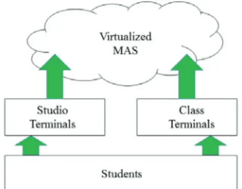
Because the performance of SculptPrint is directly dependent upon GPU power, the application has been implemented on student-accessible hardware-accelerated virtual machines (VMs) at Georgia Tech; this will allow students without access to a powerful GPU to use SculptPrint from any computer or terminal. Figure 14 shows a high-level overview of the cloud-based virtualized DFM idea, which is
accessible from anywhere on the Internet. The cloud implementation was performed using the Citrix XenDesktop environment with NVIDIA GRID graphics hardware. A diagram of this implementation is shown in Figure 15. XenDesktop allows for virtual access to NVIDIA’s Compute Unified Device Architecture (CUDA) libraries that enable the parallel computation required for SculptPrint. The feasibility of this implementation is being investigated at the other partner universities to allow a fully virtualized experience without requiring the installation of workstations in the classrooms that will make use of this work. The virtual desktops will also allow students to perform manufacturability analysis at home or anywhere else they have internet access.
Simple Challenging Difficult
Tool sizing based on part features
Machine axis configuration and fixturing
Path planning for multi-axis machines Table 3:DFM Question Categories for SM
Simple Challenging Difficult
Process selection based on feature size.
Identifying the features which require support structures.
Part orientation to minimize time and amount
of material. Table 4:DFM Question Categories for AM
5 Conclusions
A critical element in product creation is the realization, or manufacture, of the product’s design. For instance, an engineer may design the “better mousetrap”; however, if it cannot be produced in a cost effective and efficient manner, it will have little impact. All engineers, regardless of their domain, learn about scaling of system and component prototypes to full production. One of the key premises in the consideration of production scaling is the evaluation of all options available to fabricate the product. In the past, machining, or subtractive manufacturing, has been a staple of mass production. Given the significant global capital investment in machining and the capabilities of SM, it still one of the most widely utilized manufacturing processes in production and will remain so for the foreseeable future. Conversely, AM is a relatively new manufacturing technology that is presently not heavily used in mass production operations. That is beginning to change, however, as recent trends indicate that AM is being introduced to manufacturing lines.
AM has rapidly become a popular option for engineering students to prototype their designs during their studies, bolstering the use of AM in industry as a new generation of engineers moves into the workforce. There are a wide variety of reasons that AM is appealing from a “build” perspective, including its flexibility, ease of use and relatively low costs (for certain types of AM processes, e.g., FDM). This has led to the situation where newly minted engineers tend to almost exclusively consider only AM processes for producing their designs rather than the entire spectrum of process options available to them. This paper presents an approach leveraging high performance computing that provides new engineers with the ability to consider both AM and SM realms seamlessly. Through the use of rapid DFM analysis and G-Code generation, this approach eliminates the steep learning curve associated with traditional manufacturing processes that presents a significant barrier to entry for new students. The new framework described here provides a shortcut for all students to engage in DFM and physical process implementation, without the usual startup cost associated with CAM for NC. Our approach has proven to be successful in a preliminary trial at Georgia Tech, where (as one example) a student with little 5-axis machining experience was able to fully utilize a dormant machine tool that had been unused for years due to its complexity. Within a matter of weeks and with no formal training, the student was creating complex 5-axis (4+1) parts using the manufacturability analysis software described in this work. A distributed approach has been proposed that will be applied and tested in undergraduate courses at the three partner universities (Georgia Tech, Virginia Tech, and Penn State) in 2016.
6 Acknowledgements
This work was supported by NSF CMMI grants 1547093 (GT), 1547021 (PSU), 1546985 (VT), and CPS grant 1329742 (GT). Special thanks to the Office of Information Technology at Georgia Tech for support with the VM implementation.
7 References
3DSlicer. 3D Slicer: A multi-platform, free and open source software package for visualization and medical image computing [Online]. Available: http://www.slicer.org/.
Anderson, C. 2012. Makers: The New Industrial Revolution, New York, Crown Business.
Baumers, M., Tuck, C., Wildman, R., Ashcroft, I. & Hague, R. Energy inputs to additive manufacturing: does capacity utilization matter? EOS,1000,30-40.
Bralla, J. 1999. Design for Manufacturability Handbook, McGraw-Hill Education.
Carter, J. A., Tucker, T. M. & Kurfess, T. R. 2008. 3-Axis CNC Path Planning Using Depth Buffer and Fragment Shader. Computer-Aided Design and Applications,5.
EOS Design Rules for DMLS. EOS, GmbH.
Flowers, J. & Moniz, M. 2002. Rapid prototyping in technology education. Technology Teacher,62, 7-25.
Frazier, W. E. 2014. Metal additive manufacturing: A review. Journal of Materials Engineering and Performance,23,1917-1928.
Geraedts, J., Doubrovski, E., Verlinden, J. & Stellingwerff, M. Three views on additive manufacturing: business, research and education. Ninth Int. Symp. Tools Methods Compet. Eng., I. Horváth, A. Albers, M. Behrendt, and Z. Rusák, Eds, 2012. 1-15.
Gibson, I., Rosen, D. W. & Stucker, B. 2010. Additive Manufacturing Technologies, New York, NY, Springer.
Hossain, M. M., Tucker, T. M., Kurfess, T. R. & Vuduc, R. W. 2015. A GPU-parallel construction of volumetric tree. Proceedings of the 5th Workshop on Irregular Applications: Architectures and Algorithms.Austin, Texas: ACM.
Huang, S., Liu, P., Mokasdar, A. & Hou, L. 2013. Additive manufacturing and its societal impact: a literature review. The International Journal of Advanced Manufacturing Technology,67, 1191-1203.
Kim, W. 2015. A Framework for Set-Based Manufacturing Analysis and Visual Feedback.Doctor of Philosophy, The Pennsylvania State University.
KISSlicer KISSlicer Software. http://www.kisslicer.com/.
Konobrytskyi, D. 2013. Automated CNC Tool Path Planning and Machining Simulation on Highly Parallel Computing Architectures.PhD, Clemson University.
Lipson, H. & Kurman, M. 2013. Fabricated: The New World of 3D Printing, New York, NY, Wiley. Meisel, N. A. & Williams, C. B. 2015. Design and Assessment of a 3D Printing Vending Machine. Rapid
Prototyping Journal,21,471-481.
Menold, J., Jablokow, K. W., Ferguson, D., Purzer, S., Zappe, S., Reeves, P. & Kisenwether, L. Best Practices in Survery Development for the Evaluation of Student Gains from Entrepreneurship Programs and Classes. Open 2015, VentureWell's 19th Annual Conference, 2015a Washington, D.C.
Menold, J., Jablokow, K. W., Purzer, S., Ferguson, D. M. & Ohland, M. W. 2015b. Using an Instrument Blueprint to Support the Rigorous Development of New Surveys and Assessments in Engineering Education. Seattle, Washington: ASEE Conferences.
Munguía, J., Ciurana, J. d. & Riba, C. 2008. Pursuing successful rapid manufacturing: a users' best
-practices approach. Rapid Prototyping Journal,14,173-179.
Pîrjan, A. & PHWURúDQX'-M. 2013. The impact of 3d printing technology on the society and economy. Journal of Information Systems & Operations Management,7,360-370.
Repetier Software. http://www.repetier.com/. ReplicatiorG Software. http://replicat.org/.
Rosen, D. 2014. Design for Additive Manufacturing: Past, Present, and Future Directions. Journal of Mechanical Design,136,090301-090301.
Shukor, S. A. & Axinte, D. 2009. Manufacturability analysis system: issues and future trends. International Journal of Production Research,47,1369-1390.
Slic3r Software. http://slic3r.org/.
Tarbutton, J. A., Kurfess, T. R., Tucker, T. & Konobrytskyi, D. 2013. Gouge-free Voxel-Based Machining for Parallel Processors. The International Journal of Advanced Manufacturing Technology,69.
Tarbutton, J. A., Kurfess, T. R. & Tucker, T. M. 2010. Graphics Based Path Planning for Multi-Axis Machine Tools. Computer-Aided Design and Applications,7.
Turley, S. P., Diederich, D. M., Ligetti, C. B., Finke, D. A., Jayanthi, B. K., Datar, A., Saldana, C. & Joshi, S. Automated process planning and CNC-Code generation. 2014 / 01 / 01 / 2014. Institute of Industrial Engineers, 2138-2144.
Williams, C. B., Mistree, F. & Rosen, D. W. 2011. A Functional Classification Framework for the Conceptual Design of Additive Manufacturing Technologies. Journal of Mechanical Design, 133,121002-121002.
Williams, C. B., Sturm, L. D. & Wicks, A. E. 2015. Advancing Student Learning of Design for Additive Manufacturing Principles through an Extracurricular Vehicle Design Competition. ASME IDETC Design Education Conference.Boston, MA.
Wong, K. V. & Hernandez, A. 2012. A review of additive manufacturing. ISRN Mechanical Engineering, 2012.
Wright, S. M., Silk, E. M., Daly, S. R., Jablokow, K. W. & Yilmaz, S. 2015. Exploring the Effects of Problem Framing on Solution Shifts: A Case Study. ASEE Annual Conference on Engineering Education.Seattle, Washington: ASEE Conferences.
Yong, C. & Xiaoshu, X. Manufactruability Analysis of Infeasible Features in Polygonal Models for Web-Based Rapid Prototyping. Manufacturing Automation (ICMA), 2010 International Conference on, 13-15 Dec. 2010 2010. 120-127.
Yoon, H.-S., Lee, J.-Y., Kim, H.-S., Kim, M.-S., Kim, E.-S., Shin, Y.-J., Chu, W.-S. & Ahn, S.-H. 2015. A comparison of energy consumption in bulk forming, subtractive, and additive processes: Review and case study. International Journal of Precision Engineering and Manufacturing-Green Technology,1,261-279.