Software-Driven and Virtualized Architectures
for
Scalable 5G Networks
by
Mehrdad Moradi
A dissertation submitted in partial fulfillment of the requirements for the degree of
Doctor of Philosophy
(Computer Science and Engineering) in The University of Michigan
2018
Doctoral Committee:
Professor Z. Morley Mao, Chair
Assistant Professor N M Mosharaf Kabir Chowdhury Associate Professor Harsha Madhyastha
Mehrdad Moradi [email protected]
ORCID iD: 0000-0001-8158-2759
c
Mehrdad Moradi 2018 All Rights Reserved
This dissertation is dedicated to my family
for their endless love, support, and encouragement.
ACKNOWLEDGEMENTS
I could not complete this dissertation without the encouragement and support of many great people. First, I would like to thank my research advisor, Professor Z. Morley Mao. Morley has taught me more than I could ever give her credit here. She helped me to improve my research, writing, presentation, and critical thinking skills. More importantly, she created a unique opportunity and environment for me to collaborate with six different network operators and vendors (AT&T, NEC, Ericsson, Nokia, Huawei, and China Mobile) and to solve some real problems in managing hyper-scale cellular and datacenter networks. Second, I want to greatly thank my lovely wife, Maryam, for being able to accompany me for six years during the Ph.D. program. Thank you for your constant support through the ups and downs. While it has been bumpy at times, your confidence in me has enhanced my ability to get through it all and succeed in the end.
I would also like to thank my dissertation committee, Professor Harsha Madhyastha, Professor Mosharaf Chowdhury and Professor Neda Masoud, for their time and effort to help improve and refine my work. I will never forget Neda’s help in the last minutes before my thesis proposal. Moreover, I appreciate Dr. Shubho Sen and Dr. Oliver Spatscheck from AT&T Labs for their great technical discussions and guidance throughout the SoftBox work, where we designed a radical low-latency 5G architecture from the ground up. I truly enjoyed working with Shubho in the past two years. Words cannot express my gratitude enough when I think about his kindness and expertise. I also appreciate Dr. Karthik Sundaresan’s and Dr. Eugene Chai’s mentorship and support throughout my 8-month internship at NEC Labs in Princeton. The SkyCore project, where we built real UAV-based 5G cellular networks,
could not be a successful work without their continuous and valuable help and support. Besides being experts in wireless networking, Karthik and Eugene are fantastic people in other aspects of life.
At the early stage of my graduate studies, Dr. Li Erran Li was the first person who taught me how to think out-of-the-box by guiding me in the design and development of the SoftMoW project aimed at conceptualizing the first hierarchical and recursive software-defined architecture for globally controlling continent-wide cellular networks. I am also deeply thankful to Dr. Ying Zhang who offered me to do my first internship in the US at Ericsson research and truly supported me before and during the internship. Ying waited four months until Ericsson got necessary permissions from the US government to hire me. Finally, I thank Professor Mike Reiter and Professor Feng Qian who have been the most influential people in improving my academic writing skills. I always remember their great annotations all over my first paper draft in the Caesar project where I had to realize a complex memory-efficient white box switch and router design.
The six-year life in graduate school has become wonderful because of many colleagues and friends. I would like to thank all the students in our group: Yikai Lin, Ashkan Nikravesh, Shichang Shawn Xu, Sanae Rosen, Yihua Guo, Alfred Qi Chen, Jeremy Erickson, David Ke Hong, Yuru Shao, Xiao Zhu, and Yunhan Jia. I would also like to thank other friends in the department, particularly for valuable discussions and suggestions on my works: Dr. Hamed Yousefi, Amir Rahmati, Ofir Weisse, Morteza Sheikhsofla, and Javad Bagherzadeh.
Finally, but not least, my thanks go to my parents, Shahrbanoo Farahzadi and Esmaeil Moradi, who have been a true source of inspiration and love throughout my life. My parents always supported me to be an independent thinker and have confidence in my abilities to follow new things that inspire me. Finally, my most heartfelt thanks to my brothers, Dr. Mohammad Moradi and Dr. Alireza Moradi, and my sister Mozhgan. This dissertation is heartily dedicated to them.
TABLE OF CONTENTS
DEDICATION . . . ii
ACKNOWLEDGEMENTS. . . iii
LIST OF FIGURES . . . viii
LIST OF TABLES . . . xi
ABSTRACT . . . xii
CHAPTER I. Introduction . . . 1
1.1 Background and Thesis Statement . . . 1
1.2 Overview and High-level Approach . . . 4
II. SkyCore: Moving Core to the Edge for Untethered and Reliable UAV-based 5G Cellular Networks . . . 9
2.1 Introduction . . . 9
2.1.1 Summary of Contributions and Broader Implications . . 13
2.2 Motivation . . . 14
2.2.1 UAV-based LTE Networks . . . 14
2.2.2 EPC Primer . . . 14
2.2.3 Limitations of Legacy EPC Architecture . . . 15
2.2.4 Challenges in Edge EPC Architecture . . . 18
2.3 SkyCore: Design Overview . . . 21
2.4 Software Refactoring of EPC . . . 22
2.4.1 Minimalistic SkyCore Agent Architecture . . . 22
2.4.2 SkyCore Precomputed Policy Data Store . . . 26
2.5 Efficient Inter-Agent Communication . . . 28
2.5.1 Scalable SDN Control and Data Overlays . . . 28
2.6 Implementation . . . 31
2.7 Evaluation . . . 33
2.7.1 Small-Scale On-Drone Evaluation . . . 33
2.7.2 Large-Scale On-Drone Evaluation . . . 36
2.7.3 Scaling to Powerful UAV Platforms . . . 40
2.8 Related Work . . . 41
III. SoftBox: A Customizable and Low-Latency, and Signaling-Efficient 5G Core Network Architecture . . . 42
3.1 Introduction . . . 42
3.1.1 Summary of Contributions and Roadmap . . . 45
3.2 Motivation and Context . . . 46
3.2.1 Design Goals for SoftBox . . . 46
3.2.2 EPC Architecture Challenges . . . 47
3.3 SoftBox Core Architecture . . . 49
3.3.1 Need for the SoftBox Architecture . . . 49
3.3.2 Overview: Transforming EPC into SoftBox . . . 51
3.3.3 Software & Infrastructure Components of SoftBox . . . 53
3.3.4 Connecting SoftBox to LTE RANs and UEs . . . 56
3.3.5 Putting all together: Orchestration of UE containers . . . 57
3.3.6 Optimized SoftBox: Design & Optimization Challenges 58 3.4 Scalable and Flexible Optimization of Idle UE Containers . . . 61
3.5 Traffic Steering With Minimal and Stable Forwarding Rules . . . . 64
3.6 Scalable & Mobility-Aware UE Container Migration Scheme . . . 67
3.6.1 Distributed Planning of UE Container Migrations . . . . 68
3.6.2 Mobility-Aware Heuristics for UE Container Migrations 69 3.7 Scalable Interaction of SoftBox Core and LTE RAN . . . 70
3.7.1 Fast and Mobility-Aware UE Container Discovery . . . . 71
3.7.2 Connectionless RAN-Core Signaling Traffic . . . 72
3.8 Evaluation . . . 73
3.8.1 Prototype and LTE Dataset . . . 74
3.8.2 Evaluation of Basic SoftBox Architecture . . . 75
3.8.3 Evaluation of Optimized SoftBox Architecture . . . 78
3.9 Related Work . . . 83
IV. SoftMoW: A Scalable and Reconfigurable 5G WAN Architecture . . . 86
4.1 Introduction . . . 86
4.1.1 Summary of Contributions . . . 88
4.2 SoftMoW Design Overview . . . 89
4.2.1 SoftMoW Components . . . 89
4.2.2 Design Challenges and Solutions . . . 90
4.3.2 G-Switch Virtual Fabric . . . 95
4.3.3 Controller Architecture . . . 96
4.4 Core Services . . . 97
4.4.1 Recursive Topology Discovery . . . 98
4.4.2 Route Computation . . . 101
4.4.3 Global Path Implementation . . . 103
4.5 Operator Applications . . . 107
4.5.1 UE Bearer Management . . . 108
4.5.2 UE Mobility . . . 109
4.5.3 Region Optimization and Reconfiguration . . . 111
4.6 Discussion . . . 114
4.7 Implementation and Evaluation . . . 116
4.7.1 Prototype and Methodology . . . 117
4.7.2 Routing Performance . . . 118
4.7.3 Discovery Protocol Performance . . . 119
4.7.4 Handover Optimization . . . 119
4.8 Related Work . . . 121
V. Caesar: A High-Speed and Memory-Efficient Forwarding Engine for Next-Generation Internet and Cellular Core Architectures . . . 123
5.1 Introduction . . . 123
5.1.1 Summary of Contributions . . . 125
5.2 Background and Motivation . . . 127
5.2.1 Caesar Design Goals and Challenges . . . 128
5.2.2 Caesar Architecture Overview . . . 131
5.3 Primary Forwarding Path . . . 131
5.3.1 Scalable and Reliable Filters . . . 133
5.3.2 Memory Technology for Filters . . . 136
5.3.3 Parallel Lookup of Filters . . . 137
5.3.4 Reducing Next-Hop Fast Memory . . . 140
5.4 Backup Forwarding Path . . . 141
5.4.1 High-Speed False Positive Detection . . . 141
5.4.2 Blacklisting Mechanism . . . 142
5.5 Forwarding Optimizations . . . 143
5.5.1 Scalable Hash Computation . . . 143
5.5.2 Optimized Route Update Support . . . 145
5.6 Evaluation . . . 147
5.6.1 Cost-Accuracy Analysis . . . 147
5.6.2 Extensive Trace-Driven Simulation . . . 150
5.7 Related Work . . . 156
LIST OF FIGURES
Figure
1.1 4G cellular wide area network (WAN) with two regions . . . 1
1.2 A cellular core region-RAN+EPC network . . . 2
1.3 Software-defined networking (SDN) . . . 4
1.4 Network function virtualization (NFV) . . . 4
1.5 Mobile edge computing (MEC) . . . 4
1.6 Summary of projects supporting this dissertation . . . 5
2.1 LTE UAV networks. . . 10
2.2 Legacy EPC architecture. . . 13
2.3 (a) AT&T’s and (b) Verizon’s Cell on Wings . . . 14
2.4 (a) Degraded throughput on EPC-RAN link (10 MHz LTE link) when UAV flies in LOS and NLOS (over a building) trajectory. (b) # of SCTP/TCP (user data) retransmissions in NLOS . . . 15
2.5 Legacy EPC variants for UAV networks . . . 16
2.6 Capacity bottleneck . . . 18
2.7 Edge EPC for LTE UAVs . . . 18
2.8 Edge-EPC has high overheads on UAVs and results in performance bottle-necks and degraded user experience . . . 18
2.9 EdgeEPC fails in seamlessly handling increased handoffs in our LTE UAV environment . . . 20
2.10 SkyCore network architecture . . . 21
2.11 SkyCore refactors the EPC functionality into a lightweight agent having new interfaces for interaction with the local UAV and other UAVs. . . 21
2.12 SkyCore’s precomptation of network policies not only makes the core resource-efficient but also minimizes network access delay . . . 25
2.13 (a) SkyCore’s network-wide control and data plane connectivity for LTE UAV networks. (b) Example of our segment routing . . . 28
2.14 Multi-UAV SkyCore prototype . . . 31
2.15 LTE hotspot use case–exchanged data traffic over time . . . 34
2.16 Standalone LTE network use case–control plane timeline . . . 34
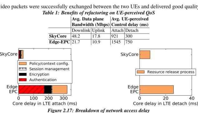
2.17 Breakdown of network access delay . . . 35
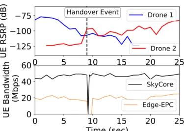
2.18 SkyCore provides seamless active-mode mobility while Edge-EPC causing severe connection drops . . . 36
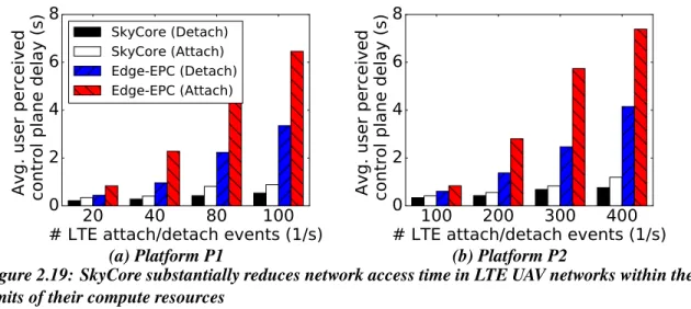
2.19 SkyCore substantially reduces network access time in LTE UAV networks
within the limits of their compute resources . . . 37
2.20 SkyCore uses minimal CPU resource to handle large-scale network access requests . . . 37
2.21 SkyCore efficiently and seamlessly supports large-scale idle-mode and connected-mode UE mobility between UAVs. . . 38
2.22 SkyCore supports large-scale idle-mode and connected-mode user mobility among UAVs in a resource-efficient manner . . . 38
2.23 SkyCore’s refactoring of the EPC increases the data rate support on resource-challenged UAVs. . . 39
2.24 SkyCore’s refactoring of the EPC minimizes the CPU resource needed on UAVs for achieving a specific data rate . . . 40
3.1 SoftBox consolidates the policies associated with each UE into a UE container in its proximity. . . 43
3.2 EPC network architecture . . . 46
3.3 Three conceptual benefits of SoftBox core networks . . . 48
3.4 SoftBox redesigns the cellular core to build customized, signaling-efficient, and low latency services. . . 51
3.5 Our scalable and flexible optimization of idle UEs’ container . . . 62
3.6 Our “recursive middleboxes” abstraction to scalably steer UEs’ traffic through containers . . . 65
3.7 Our container migration scheme with the distributed planning & mobility-aware heuristics . . . 68
3.8 Connectionless per-UE mobility management equipped with mobility-aware service discovery protocol. . . 70
3.9 Setup in the D2D experiment . . . 74
3.10 Effects of optimizing idle UEs’ container . . . 75
3.11 Effects of optimizing UE container migrations . . . 80
3.12 Efficiency of our migration algorithms . . . 80
3.13 Effects of our traffic steering optimization. . . 82
4.1 An LTE WAN with two regions . . . 86
4.2 A 3-level SoftMoW architecture . . . 94
4.3 SoftMoW controller architecture . . . 96
4.4 A link discovery example in SoftMoW . . . 100
4.5 Local optimal v.s. global optimal . . . 103
4.6 Recursive label swapping . . . 105
4.7 UE management application . . . 107
4.8 Inter-region handover optimization . . . 110
4.9 End-to-end hop count . . . 115
4.10 End-to-End latency . . . 115
4.11 Convergence time . . . 115
4.12 Cellular loads on balanced regions . . . 116
4.13 Handover optimization . . . 120 5.1 Caesar architecture. The backup path result is selected when MM
(multi-5.2 Caesar’s scalable and reliable filter construction in border router R. . . 132 5.3 Two options for a parallel membership test in TCAM when there is no
false positive andkis 2 . . . 139 5.4 Address removal and insertion in filters whenkandnmax are 2, and thus
s=blog2(nmax)c+1=2 . . . 145
5.5 Cost-accuracy analysis . . . 149 5.6 Address length vs. total cost of TCAM-based IP routers and Caesar routers
withw=288,nmax=4 . . . 150
5.7 Determiningnmax. (a) Average filter utilization ratio of filters forw=144
across all snapshots. (b) Distribution of ADs in IADs in the first and last snapshots. . . 152 5.8 Total search energy breakdown forw=144. . . 154 5.9 Normalized processing overhead of the hierarchical and flat schemes . . . 155
LIST OF TABLES
Table
1 Benefits of refactoring on UE-perceived QoS . . . 35
1 SoftBox in the SDN/NFV design space . . . 48
2 Summary of design decisions in the basic version of SoftBox. . . 49
3 Summary of design decisions in the optimized version of SoftBox. . . 61
4 EPC & SoftBox signaling overheads–**:common . . . 74
5 Average RTTs for the D2D traffic . . . 75
6 Effects of our container discovery optimization . . . 82
1 SoftMoW Controller Abstractions . . . 119
1 Fast memory reference price . . . 148
2 Experiment statistics . . . 150
3 Multi-match rate and TCAM memory consumption forw=144and vari-ablenmax. . . 151
ABSTRACT
In this dissertation, we argue that it is essential to rearchitect 4G cellular core networks–sitting between the Internet and the radio access network–to meet the scalability, performance, and flexibility requirements of 5G networks. Today, there is a growing consensus among operators and research community that software-defined networking (SDN), network func-tion virtualizafunc-tion (NFV), and mobile edge computing (MEC) paradigms will be the key ingredients of the next-generation cellular networks. Motivated by these trends, we design and optimize three core network architectures, SoftMoW, SoftBox, and SkyCore, for dif-ferent network scales, objectives, and conditions. SoftMoW provides global control over nationwide core networks with the ultimate goal of enabling new routing and mobility opti-mizations. SoftBox attempts to enhance policy enforcement in statewide core networks to enable low-latency, signaling-efficient, and customized services for mobile devices. Sky-Core is aimed at realizing a compact core network for citywide UAV-based radio networks that are going to serve first responders in the future. Network slicing techniques make it possible to deploy these solutions on the same infrastructure in parallel. To better support mobility and provide verifiable security, these architectures can use an addressing scheme that separates network locations and identities with self-certifying, flat and non-aggregatable address components. To benefit the proposed architectures, we designed a high-speed and memory-efficient router, called Caesar, for this type of addressing scheme.
CHAPTER I
Introduction
1.1
Background and Thesis Statement
Cellular networks have become an integral part of our society. We use them to make phone calls, check news, watch videos, and make transactions. They are distributed throughout large geographical areas (e.g., a country) and consist of tens of thousands of packet processing elements (e.g., gateways, base stations).
PGW SGW1 SGWn S1U S1U S5 S5 Internet S1U S1U Region 1 Region 2
Figure 1.1: 4G cellular wide area network (WAN) with two regions
Today’s 4G wide area networks (WANs) are organized into very large regions (Figure 1.1), each having an evolved packet core (EPC) network and a radio access network (RAN). Each EPC (Figure 1.2) contains an Internet edge comprised of packet data network gateways (PGWs) and a radio edge connecting to RAN. RAN consists of only base stations and
UEs’ signaling and data traffic; it enforces network policies, provides always-on Internet connectivity, and offers seamless mobility support.
PCRF MME [NAS, S1AP, SCTP] GTP-C Diameter GTP-C Diameter ISP PGW GTP-U HSS Diameter LTE RAN
EPC
GTP-U SGW GoogleData plane Control plane Signaling Data
eNB UE
Figure 1.2: A cellular core region-RAN+EPC network
EPC has a hierarchical structure partitioning its functions among a group of dedicated nodes. At the Internet edge, the PGW connects the core to Internet/content providers and enforces most of the data plane policies (e.g., NAT, DPI). At the RAN edge, enhanced node Bs (eNodeBs) are grouped into logical serving areas and connect to serving gateways (SGWs). Each SGW acts as a mobility anchor point for its eNodeBs. It also forwards each UE’s data traffic between the eNodeB and PGW using a separate GTP-U (GPRS tunneling protocol) tunnel. To connect to the network, UEs must register with the mobility management entity (MME) through eNodeBs. MME continuously exchanges signaling traffic with UEs and eNodeBs to perform security and mobility functions (e.g.,authentication, handover). To handle these tasks, MME accesses home subscriber server (HSS) that is a centralized database containing UE-related information (e.g.,SIM card key). For connected UEs, policy and charging rule function (PCRF) authorizes the treatment that UEs’ data flows receive by supplying QoS rules to PGW/SGW in real time.
Unfortunately, today’s EPC networks suffer from an increasing pressure on their scalabil-ity, performance, and flexibility. Thus, operators are actively exploring different designs for 5G core networks to overcome the EPC challenges and meet emerging 5G use cases.
• Scalability challenges. First, the number of global LTE subscribers is around 1.2 billion with a peak daily addition of 2 million devices since 2016 [26]. On the one hand, this
trend and the continued exponential growth of mobile traffic put tremendous pressure on the EPC’s data plane scalability. Soon, mobile traffic will represent around 20% of total IP traffic on the Internet. On the other hand, the fast growth of signaling traffic from mobile UEs poses a major challenge to scalability of EPC’s control plane [27]. In response to each UE signaling messages, EPC generates a huge amount of internal control plane overheads or signaling storms [14, 27] due to its complex nodes and distributed protocols.
• Flexibility challenges. Second, diversity of devices supporting LTE is going beyond cell phones and is reaching to domestic robots, sensors, and cars. Unfortunately, the EPC networks control and data planes lack fine-grained customizability and programmability. EPC cannot easily realize diverse and customized 5G services for new use cases (e.g., public safety, tactile Internet, autonomous cars) [90].
• Performance challenges. Third, while many 5G use cases require ultra-low latency and gigabit bandwidth, recent studies show that mobile application performance is seriously degraded by EPC’s inefficient policy enforcement and routing. EPC routes traffic of UEs destined to the Internet or other nearby UEs on long suboptimal paths between RAN and PGW [130]. Moreover, there is no control plane interaction between EPC instances located in different regions. Thus, UEs crossing region boundaries experience significant service disruption.
Thesis statement.To address these challenges and realize emerging 5G use cases, my thesis statement is that cellular networks, particularly their core, must be rearchitected to provide scalability, flexibility, and performance as their first-order properties.
•
Software-defined networking (SDN)
o
Programmability and automation in design, reconfiguration, and
management of networks
4
Networking Paradigm Shifts (1)
P4 OpenFlow
Data plane Figure 1.3: Software-defined networking (SDN)
Networking Paradigm Shifts (2)
•
Network function virtualization (NFV)
o
Migrate functions running on dedicated hardware to commodity X86 servers
5
Hardware Network Functions Virtualized Network Functions
Operators’ Public/Private
Cloud
CDN
DPI Firewall Carrier Grade NAT Session Border Controller WAN Acceleration PE
Router BRAS Network NodeRadio Access Message
Router
Commodity servers, switches, and storage units Orchestration & Automation
Figure 1.4: Network function virtualization (NFV)
Networking Paradigm Shifts (3)
•
Mobile edge computing (MEC)
o
Cloud computing capabilities close to radio edges of cellular networks
6 MEC Server Cellular Core Network ISP Google Edge DC
Figure 1.5: Mobile edge computing (MEC)
1.2
Overview and High-level Approach
Today, there is a growing consensus that software-defined networking (SDN), network function virtualization (NFV), and mobile edge computing (MEC) will be the dominating ingredients of 5G networks. SDN is a network design paradigm that advocates for pro-grammability and automation in design, reconfiguration, and managing networks. A typical
software-defined network consists of a logically centralized controller and programmable switches (Figure 1.3). NFV is a network architecture concept arguing for migrating network functions (NFs) that traditionally run on complex dedicated hardware to commodity x86 servers (Figure 1.4). Finally, MEC (Figure 1.5) is a conceptual proposal that attempts to provide cloud computing capabilities close to radio edges of cellular networks to run low-latency applications (e.g., big data and machine learning). We combine the benefits of the SDN, NFV, and MEC paradigms in four different projects (as summarized in Figure 1.6) to support the thesis statement.
Overview & Roadmap
Scalability & Reconfigurability SkyCore (Chapter 2) Reliability & Flexibility SoftBox (Chapter 3)
Low latency & Customizability
SoftMoW
(Chapter 4)
Forwarding Performance & Low memory usage
Caesar
(Chapter 5) 5G Cellular Core/WAN Architectures
Control plane and data plane designs based on SDN/NFV/MEC for Next-Gen ArchitecturesRouter/Switch Design
Citywide Statewide Nationwide
Network
Scale Internet-scale
Design Goals Project
Figure 1.6: Summary of projects supporting this dissertation
In particular, we first design and optimize three 5G core network architectures for differ-ent network conditions, objectives and scales: (1) SkyCore that is an efficidiffer-ent core network solution for UAV-based LTE RANs that are going to provide on-demand LTE coverage for first responders and general public in citywide challenging environments, (2) SoftBox that is a low-latency, signaling-efficient, and customizable core network covering larger scale statewide LTE RANs, and (3) SoftMoW that is a scalable and dynamic cellular WAN archi-tecture for managing nationwide LTE RANs. Finally, we present Caesar that is a high-speed and memory-efficient router architecture and can be deployed as a complementary solution in SkyCore, SoftBox, and SoftMoW or other future Internet architectures to improve mobility
support and verifiable security. In the following, we provide a more detailed overview of each of these projects.
In chapter 2, we discussSkyCore: moving core to the edge for untethered and reliable UAV-based LTE networks. The advances in unmanned aerial vehicle (UAV) technology has empowered mobile operators to deploy LTE base stations (BSs) on UAVs, and provide on-demand, adaptive connectivity to hot-spot venues as well as emergency scenarios. However, EPC that orchestrates the LTE RAN faces fundamental limitations in catering to such a challenging, wireless and mobile UAV environment, particularly in the presence of multiple BSs (UAVs). In this work, we argue for and propose an alternate, radicaledgeEPC design, called SkyCore that pushes the EPC functionality to the extreme edge of the core network – collapses the EPC into a single, light-weight, self-contained entity that is co-located with each of the UAV BS. SkyCore incorporates elements that are designed to address the uniques challenges facing such a distributed design in this UAV environment, namely the resource-constraints of UAV platforms, and the distributed management of pronounced UAV and UE mobility. We build and deploy a fully functional version of SkyCore on a two (rotary-wing) UAV LTE network and showcase its (i) ability to inter-operate with commercial LTE BS as well as smartphones, (ii) support both hot-spot and stand-alone multi-UAV deployments, and (iii) superior control and data plane performance compared to other EPC variants in this environment.
In chapter 3, we presentSoftBox: a customizable, low-latency, and scalable 5G core network architecture.SoftBox combines SDN, NFV, and MEC to enable the creation of customized, low latency, and signaling-efficient services on a per user equipment (UE) basis. SoftBox consolidates network policies needed for processing each UE’s data and signaling traffic into a light-weight, in-network, per-UE agent. We designed a number of mobility-aware techniques to furtheroptimize: resource usage of agents, forwarding rules and
updates needed for steering a UE’s traffic through its agent, migration costs of agents needed to ensure their proximity to mobile UEs, and complexity of distributing the LTE mobility function on agents. In this project, we demonstrate that basic SoftBox has by 86%, 51%, and 83%-87% lower signaling overheads, data plane delay, and CPU core usage, respectively, than open source EPC systems. Moreover, our optimizations efficiently cut the peak load in SoftBox networks by 51%-78%. These results point to the feasibility and potential of the SoftBox concepts.
In chapter 4, we explainSoftMoW: a scalable and reconfigurable cellular WAN archi-tecture. SoftMoW supports seamlessly inter-connected core networks distributed over a large geographical area (e.g., country or continent) by providing reconfigurable control plane and global optimization. To scale the control plane nation-wide, SoftMoW recursively builds up a hierarchical control plane with novel abstractions of both control plane and data plane entities. SoftMoW supports new network-wide optimization functions such as optimal routing and inter-region handover minimization. In this project, we demonstrate SoftMoW improves the performance, flexibility and scalability of cellular WAN using real LTE network traces with thousands of base stations and millions of subscribers. Our evaluation shows that path inflation and inter-region handovers can be reduced by up to 60% and 44% respectively.
In chapter 5, we focus onCaesar: a high-speed and memory-efficient forwarding engine for next-generation Internet and cellular core architectures. Many next-generation network architectures depart from using IP addresses. Instead, they use an addressing scheme that separates network locations and identities with self-certifying, flat and non-aggregatable address components. This addressing scheme has been successful in improving seamless mobility support and guarantees verifiable security. We can easily deploy this addressing scheme in our software-defined SkyCore, SoftBox, and SoftMoW architectures to further optimize them. However, the main challenge with this addressing scheme is that each of the
address components is often long, reaching a few kilobits, and would consume an amount of fast memory in data plane devices that is far beyond existing capacities. To address this challenge, we developCaesar, a high-speed and length-agnostic forwarding engine for future border routers, performing most of the lookups within three fast memory accesses. To compress forwarding states, Caesar constructs scalable and reliable Bloom filters in Ternary Content Addressable Memory (TCAM). Our evaluation shows that Caesar is more energy-efficient and less expensive (in terms of total material cost) compared to optimized IPv6 TCAM-based solutions by up to 67% and 43% respectively. In addition, the total cost of our design is approximately the same for various address lengths.
CHAPTER II
SkyCore: Moving Core to the Edge for Untethered and
Reliable UAV-based 5G Cellular Networks
2.1
Introduction
LTE networks that are ubiquitous today are deployed after sufficient RF planning in a region. However, the static nature of LTE base station (BS) deployments limits their ability to cater to certain key 5G use cases – surging traffic demands in hot spots (e.g. stadiums, event centers), as well as their availability in emergency situations (e.g. natural disasters), where the infrastructure could itself be compromised. Providing an additional degree of freedom for base stations, namelymobility, allows them to break away from such limitations.
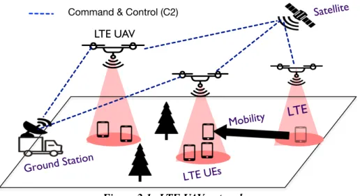
UAV-driven LTE networks. In this regard, recent advances in unmanned aerial vehicle (UAV) technology has empowered operators to take on-demand, outdoor connectivity to another level, by allowing their base stations to be deployed aerially on UAVs (Figure 2.1), thereby offering complete flexibility in their deployment and optimization. Mobile operators like AT&T and Verizon have both conducted trials with LTE base stations mounted on UAVs [8, 10] (helicopter and fixed-wing aircraft respectively, Figure 2.3). AT&T also provided connectivity service from its UAV in the aftermath of hurricane Maria in Puerto Rico last year [9]. Further, with the availability of shared access spectrum like CBRS [7] in 3.5 GHz, this also opens the door for smaller, green field operators to deploy and provide
on-Mobility
LTE UEs
LTE UAV
Command & Control (C2)
LTE
Ground Station
Satellite
Figure 2.1: LTE UAV networks.
demand, private LTE connectivity service without the heavy cost associated with spectrum and deployment.
Limitations of legacy EPC. A typical LTE network requires the deployment of two essential components: a radio access network (RAN) consisting of multiple base stations (BSs) that provide wide-area wireless connectivity to clients (UEs), and a high-speed, wired core network of gateways (evolved packet core, EPC) that sits behind the RAN and is responsible for all the mobility, management and control functions, as well as routing user traffic to/from the Internet. Realizing a multi-UAV-driven RAN (BSs deployed on UAVs) with an EPC on the groundis one way to directly apply today’s EPC architecture to the UAV environment (as shown in Figure 2.5) – this has been the case with current operator-driven UAV efforts. However, this faces significant limitations in delivering real value to this challenging environment. Specifically, while atethered set-up(EPC-UAV link being wired, Figures 2.3a, 2.5a) significantly limits the UAV’s mobility and ability to scale to multiple UAVs, awireless set-up(EPC-UAV link being wireless/mobile, Figures 2.3b, 2.5b) incurs all the vagaries of the wireless channel. For the latter, the choice of the wireless technology becomes critical given that the EPC is responsible for setting-up, routing, and tearing down all voice/data bearers. It is essential for the EPC toreliably reach all the UAVs
the traffic demands in the RAN. It is extremely challenging for a wireless technology, be it lower frequency (sub-6 GHz like LTE, WiFi, etc.) or higher frequency (mmWave), to simultaneously satisfy theneeds of range, reliability/robustness, and capacitythat the UAV environment demands from the critical EPC-RAN link.
Core at the Edge. Given the fundamental limitations in deploying an EPC on the ground to support a multi-UAV RAN, we advocate for a radical, yet standards-compliant re-design of the EPC, namely theedge-EPCarchitecture, to suit the UAV environment. As the name suggests, we aim to push theentireEPC functionality to the extreme edge of the core network, by collapsing and locating the EPC as a single, light-weight, self-contained entity on each of the UAVs (BSs) as shown in Figure 2.7. Being completely distributed at the very edge of the network, such an architecture completely eliminates wireless on the critical EPC-RAN path and hence the crippling drawbacks faced by the legacy architecture in this environment.
While definitely promising at the outset, realizing this radical design is not without its own set of challenges that are unique to the UAV environment. In particular, (i) Resource-challenged environment: The compute resources consumed by the numerous network func-tions in EPC is appreciable and becomes a concern when all the EPC functionality is collapsed into a single node, and deployed directly on a UAV platform – the latter being highly resource-challenged to begin with. This could significantly affect both the UAV’s operational lifetime as well as the processing (control and data plane) latency of its traffic, thereby resulting in a reduced traffic capacity. (ii)Mobility management: The hierarchical nature of the legacy EPC architecture, gives a single network gateway (like mobility management entity, MME) a consolidated view of multiple BSs, thereby allowing it to efficiently manage handoffs during mobility of active UEs as well as tracking/paging mobile UEs that are in idle mode. Mobility of both active (handoffs) and idle UEs (paging) becomes a critical challenge, when the entire EPC is located at each of the UAVs, thereby restricting their view of events to only those that are local to the UAV.
UAV-based LTE networks, we present our novel EPC design, SkyCore. SkyCore embodies the edge-EPC architecture, while introducing two key pillars in its design to address the associated challenges – a completesoftware refactoring of the EPCfor compute-efficient deployment on a UAV, and a newinter-EPC communication interfaceto enable fully functional operation in a multi-UAV environment. Throughsoftware-refactoring, SkyCore eliminates the distributed EPC interfaces and collapses all distributed functionalities into a single logical entity (agent) by transforming the latter into a series of switching flow tables and associated switching actions. It also reduces control plane signaling and latency by pre-computing and storing (in-memory data store) several key attributes (security keys, QoS profile, etc.) for the UEs that can be accessed quickly in real-time without any computation. To ensure complete EPC functionality, SkyCore manages mobility right at the edge of the network – it enables a new control/data interface to realize efficientinter-EPC signaling and communicationdirectly between UAVs. This allows the SkyCore agents on each UAV toproactivelysynchronize state with each other, thereby avoiding the real-time impact of wireless (UAV-UAV) links on critical control functions – results in fast and seamless handoff of active mode UEs as well as tracking of idle mode UEs across multiple UAVs.
Real-world prototype. We have built a complete version of SkyCore on a single board server with a small compute and energy footprint; and deployed it on Matrix 600 Pro rotary-wing drones to create a two-UAV LTE network. To the best of our knowledge, this is the first realization of a self-contained edge-EPC solution that can support a multi-UAV network and is a direct affirmation of SkyCore’s design. SkyCore’s feasibility and functionality is validated by seamless integration and operation with a commercial LTE RAN (BS) from ip.access and off-the-shelf UEs (Moto G and Nexus smartphones). We demonstrate SkyCore UAVs to operate both as hot-spots that allow for better UE connectivity to the Internet, as well as for stand-alone connectivity of geographically separated UEs through two different UAVs (e.g. first responders in emergency scenarios), while also allowing for handoffs. Our real world evaluations of SkyCore and its comparison with a state-of-the-art software EPC
PCRF MME [NAS, S1AP, SCTP]
Pack
et
N
etw
o
rk
PGW GTP-U HSSRAN
EPC
SGWData plane Control plane Signaling Data
eNB UE
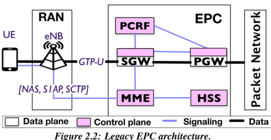
Figure 2.2: Legacy EPC architecture.
(OpenEPC [34]) on UAV clearly showcases SkyCore’s superior performance and scalability – SkyCore provides an order of magnitude lower control plane latencies, incurs 5×lower
CPU utilization, and provides data plane rates that currently scale up to a Gbps.
2.1.1 Summary of Contributions and Broader Implications
Our two key contributions in this chapter include,
• A novel edge-EPC solution, SkyCore that canreliably and scalablysupport a stand-alone, multi-UAV LTE network deployment that was not possible earlier.
• A real-world implementation and evaluation that showcases both its feasibility and its superior performance.
SkyCore’s underlying design is driven by the observation that when connectivity between core network functions, which are on the critical path, is unreliable (wireless and mobile), the merits of pushing functionality to the edge of the network significantly outweighs the associated drawbacks. Hence, although designed for a multi-UAV environment, SkyCore’s design can also benefit other deployments, where distributed critical network functions have to communicate over unreliable links (e.g. distributed enterprise RANs).
(a) (b) Figure 2.3: (a) AT&T’s and (b) Verizon’s Cell on Wings
2.2
Motivation
2.2.1 UAV-based LTE Networks
We consider low-altitude UAV networks, such as those considered by mobile operators [8, 10] for on-demand, LTE network deployments. These are envisioned to serve as dynamic small cells that add capacity to macrocell networks in hot-spot venues, as well as provide stand-alone connectivity (without macrocells) for local communication in disaster scenarios. Relevance of our work to high-altitude, long endurance platforms like Google’s Loon [19] and Facebook’s Aquila [16] is discussed in Section 4.6. In a UAV-based LTE network, an LTE BS (eNB) is directly deployed on each UAV, and multiple of them together provide wireless connectivity to UEs over a desired wide area as shown in Figure 2.1. However, not much thought has been paid towards the deployment of an EPC to support such a RAN. Deploying and managing a traditional LTE EPC is a challenge in its own right. Designing one to support an LTE RAN on UAVs, which are highly restrictive in their compute capabilities, endurance and payload capacity, further amplifies the associated challenges.
To foster a better understanding, we first reiterate a short primer on EPC’s key function-ality, followed by the limitations of today’s EPC for our target environment, and the benefits and drawbacks of an “alternate" edge EPC architecture.
2.2.2 EPC Primer
Figure 2.2 shows the network architecture of EPC, which is a distributed system of different nodes or network functions (NFs) that are required to manage the LTE network. The EPC
consists of data and control data planes: the data plane enforces operator policies (e.g., DPI, QoS classes, accounting) on data traffic to/from user equipment (UE), while the control plane provides key control and management functions such as access control, mobility and security management. eNodeBs (RANs) are grouped into logical serving areas and connected to serving gateways (SGW). The SGW is connected to an external packet network (e.g. the internet) via a packet data network gateway (PGW). PGW enforces most of data plane policies (e.g., NAT, DPI) and may connect the core to other IP network services (e.g., video server). The mobility management entity (MME) is responsible for access control, security and mobility functions (e.g., attach/detach, paging/handoff) in conjunction with the home subscriber server (HSS) database.
2.2.3 Limitations of Legacy EPC Architecture
The straight-forward way to apply EPC to our UAV network would be to collapse all the EPC network functions into a single node (EPC-in-a-box) and deploy this EPC node on a resource-capable node on the ground that can support multiple UAV BSs. This is the approach adopted by operators like AT&T and Verizon in their recent trials (Figure 2.3) [8, 10].
0
10
20
EPC-RAN link bandwidth (Mbps)
0.00
0.25
0.50
0.75
1.00
CDF
Degraded Connectivity
LOS
NLOS
(a)200
400
600
Time (s)
0
100
200
# Control/data plane
Retransmissions
(b)
Figure 2.4: (a) Degraded throughput on EPC-RAN link (10 MHz LTE link) when UAV flies in LOS and NLOS (over a building) trajectory. (b) # of SCTP/TCP (user data) retransmissions in NLOS
2.2.3.1 Tethered Deployment (Wired EPC-UAV link)
In today’s traditional LTE networks, the connectivity between EPC and eNBs (RAN) is a reliable, wired network provisioned with sufficient bandwidth for catering to the UE traffic demands in both downlink and uplink. A similar approach can be adopted in our UAV network, where the RAN runs on the UAV, which is tethered by a wire to a ground station running the EPC (Figure 2.3a, 2.5a). However, such an approach significantly limits the potential and flexibility of the UAV to fly and re-position itself to cater to network traffic requirements, not to mention the associated safety concerns and the infeasibility of scaling such a set-up to support a network of UAVs. With UAV technology advancing at a rapid pace to provide longer operational times [4], such a tethered EPC-on-ground does not offer a viable, future-proof solution.
(a) Legacy
Wired
EPC
RAN RAN
EPC
EPC
EPC
RAN RAN
(a) Legacy
Wireless
EPC
Wireless
Figure 2.5: Legacy EPC variants for UAV networks
2.2.3.2 Un-tethered Deployment (Wireless EPC-UAV link)
The other alternative is where the connectivity between EPC on the ground and eNBs (UAVs) is wireless (Figure 2.3b, 2.5b).
Reliability vs. range vs. capacity: The wireless channel is inherently an unreliable medium, and is subject to wireless artifacts such as shadowing (building, trees, obstacles), multi path fading, etc. that can significantly degrade signal quality (by as much as 70% in our experiments, Figure 2.4a) and cause high packet retransmissions (more than 100 SCTP/TCP retransmissions, Figure 2.4b) and potentially cause disconnections. The choice of the wireless technology also plays an important role. Using lower frequencies like 700MHz, 1
GHz, etc. allows for better penetration and hence longer communication ranges and better reliability but significantly lesser bandwidth (capacity of few tens of MHz). In contrast, higher frequencies like mmWave (28 gHz, 60 GHz, etc.) offer significantly more bandwidth (hundreds of MHz to a GHz) but suffer from higher attenuation and hence lower range. While the latter can employ beamforming to cope with attenuation, they are limited by line-of-sight requirements and the need to constantly track the beam direction with respect to each UAV as they move – impediment for reliable operation in low altitude deployments. Thus, it is extremely challenging to identify a wireless modality for the critical EPC-RAN (ground to UAV) link that can offer the simultaneous features of reliable connectivity, increased communication range, and capacity, that is warranted by this EPC architecture.
Single point bottleneck:The EPC node on the ground becomes the routing focal point that ferries traffic not only between the UEs and the Internet but also between UEs within the UAV network. Hence, even if the UAV backhaul (connectivity between UAVs) is well-provisioned, having a small set of ground EPC nodes, concentrates all the traffic on the UAV backhaul towards these ground nodes, which in turn become the bottleneck. This would significantly degrade the capacity of the network as a whole. For a low altitude UAV network deployed to provide on-demand connectivity to a small geographic region, bulk of the traffic might be local – e.g. between users and content servers in events, or between first responders and/or affected people in emergencies. In such scenarios, incurring the wireless capacity bottleneck due to EPC on the ground is un-warranted.
A simple illustration in Figure 2.6 shows that the capacity offered by an EPC-on-ground architecture (capacity of x) even for a small 4-UAV network can be 6 times lower than if the local traffic were to be served directly between the UAVs (capacity of 6x). In addition, UAV and UE mobility are highly pronounced in these networks, which also leads to increased control signaling and associated latency over multiple wireless hops between the ground EPC node and the UAVs.
EPC RAN RAN RAN RAN x x
x
x x x xx Link Capacity Wireless Link
Figure 2.6: Capacity bottleneck
RAN RAN
EPC
EPC
Figure 2.7: Edge EPC for LTE UAVs
connectivity to all UAVs and to add capacity (akin to provisioning multiple gateways in wireless mesh networks [55]). However, this adds to both the cost as well as reliance on ground deployments, working against the flexibility offered by UAVs in the first place.
2.2.4 Challenges in Edge EPC Architecture
To counteract the challenges in deploying a legacy EPC architecture, we focus our attention to a radically different “edge" EPC architecture. Here, the entire EPC is collapsed and located as a single, self-contained entity on each of the UAVs as shown in Figure 2.7. Being completely distributed at the edge of the network, such an architecture would completely eliminate the crippling drawbacks of faced by the previous architecture resulting from wireless connectivity between EPC and eNBs. While definitely promising at the outset, it does encounter a different set of challenges in its realization.
1 20 40 60 80 100
# LTE attach/detach events per sec.
0
2000
4000
6000
8000
Avg. user perceived
control plane delay (ms)
Legacy-Wired (Attach) Legacy-Wired (Detach) Edge-EPC(Attach) Edge-EPC (Detach) (a)
1
20 40 60 80
# LTE attach/detach events per sec.
0
50
100
CPU utilization (%)
EPC Overload
(b)
Figure 2.8: Edge-EPC has high overheads on UAVs and results in performance bottlenecks and degraded user experience
2.2.4.1 Resource-challenged
An EPC consists of multiple network functions along with the interfaces and tunneling protocols between them. Further, most of these are stateful network functions and consist of both control and data plane functionality. These network functions, which used to be deployed by operators on specialized hardware, are now slowly migrating to a virtualization environment with the recent advances in NFV (network function virtualization [28, 109, 57]. Nevertheless, the compute resources consumed by these network functions is appreciable and becomes a concern when all the EPC functionality is collapsed onto a single node. Deploying an EPC node on the UAV could significantly affect both its operational lifetime as well as the processing (control and data plane) latency of its traffic, thereby resulting in a highly reduced traffic capacity. This can be observed in Figures 2.8a, 2.8b, where the latency and CPU utilization of control plane functions can be anorder higherin Edge-EPC, when the platform (such as that on a UAV) is resource-constrained (experimental details in Section 2.7).
2.2.4.2 Handling Mobility at the Edge
Conventional EPC has a hierarchical structure, where a single PGW spans multiple SGWs, and a single SGW spans multiple eNBs. As the UE (in active mode) moves from one cell to another (handoff), this is handled locally by its SGW. Further, every UE has a tracking area (TA, set of neighboring eNBs) associated with it, which the EPC will use to page (all eNBs in its TA) to locate it when in idle mode. When the UE moves out of its current TA, it notifies the EPC of its updated TA. Thus, UE mobility is handled seamlessly in legacy EPC.
Active-mode mobility (Handoffs). Network dynamics in the form of UE and/or UAV mobility forms a significant part of our operating environment. However, with the collapse of the hierarchical architecture in Edge-EPC, one needs to now enable communication between the EPC entities on individual UAVs to enable seamless handoff across UAVs. In today’s
0
250
500
750
1000
Time(s)
120
110
100
90
RSRP (dB)
Handoff region
UE perceived
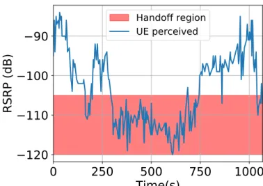
Figure 2.9: EdgeEPC fails in seamlessly handling increased handoffs in our LTE UAV environ-ment
network (a single PGW spans a significantly large area - hundreds of miles). When such an event does happen, the connection is terminated with the existing PGW and re-established with the new PGW causing service disruption. However, such events are the norm rather than an exception in our environment. Figure 2.9 illustrates the number of potential handoff events that can be triggered due to appreciable signal variations even during a short UAV flight (less than 50m) in our experiments. Hence, it becomes critical to enable seamless EPC-EPC communication for handling mobility in the edge EPC architecture. This is needed to also handle UAV mobility, i.e. when one UAV goes down for a re-charge and is replaced by another UAV – a migration of state from one UAV (EPC) to another is imperative.
Idle-mode mobility (Tracking/Paging). With the ability to page idle UEs over large tracking areas (spanning several BSs), it is fairly straight-forward to locate any UE in the network in legacy EPC. This is however, a challenge for the edge-EPC architecture, where there is no single PGW that spans all the UAVs (eNBs). Further, since the notion of tracking area disappears (due to collapsed EPC), locating a UE when in idle mode appears to be infeasible, prompting the need for new or adapted mobility mechanisms.
RAN
SkyCore
Agent
RAN SkyCore Master Backhaul Agent Backhaul Agent eNodeBSkyCore
Agent
Backhaul AgentSkyCore control plane protocols
User data over SkyCore data plane protocol Legacy EPC protocolsWireless backhaul
Figure 2.10: SkyCore network architecture
SGW-D PCRF PGW-C SGW-C MME HSS PGW-D LTE
Mobility PolicyLTE
GTP-U SCTP/ S1AP/NAS UAV Control Co ns ol id ati on & opti mi za tio n Deco upl ing EP C co ntr ol & da ta pl anes
Refactored Legacy Apps
Other UAVs SkyCore Apps Inter-Agent Communication Other UAVs or Internet EPC control plane
EPC data plane
RAN
UAV engine
Precomputed In-Memory Policy Data Store SkyCore Controller
OpenFow/P4
Step 1 Step 2-5
Charging QoS &
Rate Firewall ProcessingGTP-U SkyCore Switch
SkyCore Overlay
SkyCore Agent
Figure 2.11: SkyCore refactors the EPC functionality into a lightweight agent having new inter-faces for interaction with the local UAV and other UAVs.
2.3
SkyCore: Design Overview
SkyCore adopts the edge EPC architecture as shown in Figure 2.10. SkyCore collapses the entire EPC and pushes it to the edge of our network, namely at each of the UAVs themselves, where it is colocated with the RAN. While this completely eliminates wireless from the critical path between EPC and RAN, to address the challenges associated with the edge architecture, SkyCore introduces two novel design components. Briefly,
Software-refactoring of EPC functionality. To reduce its compute footprint on the UAV, SkyCore adopts a software refactoring approach to eliminate distributed EPC interfaces and collapse all distributed functionalities into a single logical entity. It realizes this by transforming the distributed data plane functions into a series of switching flow tables and as-sociated switching actions (corresponding to functions like GTP encapsulation/decapsulation, charging, etc.). It also reduces control plane signaling and latency by pre-computing and
UEs that can be accessed locally in real-time without any computation.
Efficient Inter-EPC communication. With every UAV now running its own EPC agent, even a simple eNB-eNB handoff of an active UE across two UAVs now becomes a inter-MME (inter-MME-inter-MME) handoff, which needs to be accomplished across two different EPC agents. SkyCore enables a new control/data interface that allows agents on different UAVs toproactively(in background) synchronize the state of UEs. This bypasses the real-time impact of wireless (UAV-UAV links) on critical control path functions, allowing for seamless handoffs and tracking of idle mode UEs right at the edge. The HSS equivalent in each SkyCore agent maintains the location (anchoring SkyCore agent) of all UEs in the network. Hence, when an agent sends a UE location update, the agents in other UAVs update their HSS accordingly. Thus, whenever traffic needs to be sent from a SkyCore agent to a specific UE located at another UAV, the HSS will reveal the destination SkyCore agent at which the UE is anchored and to whom the traffic has to be routed. The actual routing path to be taken by the traffic on the mesh backhaul is then determined by SkyCore, with the underlying backhaul topology information made available by a backhaul agent that resides on the UAV1.
We now explain each of these design components in detail.
2.4
Software Refactoring of EPC
2.4.1 Minimalistic SkyCore Agent Architecture
Each SkyCore agent has a minimalist and UAV-aware SDN-based architecture (Figure 2.11), consisting of a controller that executes the control functions to process UEs’ signaling traffic and to coordinate with other agents, and a switch that processes user data traffic. In the following, we describe five high-level steps that we take to refactor and extend the EPC functionality onto our agent architecture.
Step 1. Decoupling the EPC control and data plane pipelines. One of the main
reasons behind high complexity and overhead of EPC is its nodes performing mixed control and data plane functions. To make the EPC functionality suitable for UAVs, we first decouple the EPC control and data planes. Among the EPC nodes, MME, PCRF, and HSS are pure control nodes. Hence, our decoupling does not affect these elements, and only affects SGW and PGW. The resulting control components from the decoupling are PGW-C, SGW-C, MME, PCRF, and HSS, and the data elements include SGW-D and PGW-D (C stands for control and D for data). While the benefits of decoupling control and data planes have been articulated before [98, 86], we apply it in the context of UAV networks, and enhance it substantially with the following mechanisms.
Step 2. Categorizing the functionality of the EPC control plane. Next, we categorize the EPC control nodes based on their high-level functionality. In our decoupled EPC, there are three types of control nodes. SGW-C and PGW-C are responsible for managing QoS policy enforcement and routing on user data traffic. MME exchanges signaling traffic with UEs and BSes. PCRF and HSS dynamically generate network security and QoS policies for other nodes. To compress the EPC functionality, we try to consolidate the nodes in each category on top of our agent controller and remove the EPC distributed protocols as follows.
Step 3. Collapsing SGW-C, PGW-C, and MME into light-weight applications. We extract the internal functions in the SGW-C and PGW-C nodes and refactor them into a single SDN application, called Policy Application, on top of the controller. We do the same process for MME and transform it into a Mobility Application. One notable aspect of this consolidation is that we naturally eliminate the complex GTP-C protocol, its six interfaces, and continuous control messages from the core (Figure 2.2). This makes the corresponding SDN applications extremely lightweight and extensible without hurting their original functionality. Note that these applications still exchange information with each other but through simple local publish-subscribe mechanisms.
Step 3. Eliminating HSS and PCRF from the LTE UAV core and replacing them with a precomputed policy data store. Next, we focus on HSS and PCRF that are known
to be the source of today’s signaling storms in cellular networks [27, 35]. HSS stores hundreds of database tables containing different UEs’ states often on disk. Moreover, it acts as a proxy between MME and these tables and performs different types of complex security and location tracking computations. Similarly, PCRF often accesses a logical database (sometimes implemented in the HSS) and dynamically generates different QoS and charging policies of UEs. In SkyCore, we completely eliminate these two nodes from our agents. We show that dynamic policy generation can be carefully replaced with a precomputed in-memory policy data store. Precomputation combined with in-memory transactions substantially minimizes the overhead of the core on resource-challenged UAVs (elaborated in Section 2.4.2). This also removes the complex Diamater protocol from the core.
Step 4. Adding UAV-specific applications to the core. One of the key differences between SkyCore and traditional EPC is in its continuous interaction with the UAV hardware and its APIs. In particular, we advocate for two new applications on top of our agents. Each SkyCore agent runs UAV Control Application that listens to flight change events from UAV and remaining battery resources on the UAV. This is necessary for our agents to properly handoff UEs to each other, e.g., when a UAV needs to immediately leave the network for recharging. Such use cases clearly show the potential of our SDN-based UAV-aware architecture. In addition, we design an Inter-UAV Communication Application that exchanges control plane messages with its neighbor agents to synchronize statesproactively, thereby enabling seamless mobility (active and idle). Other legacy EPC applications and new SkyCore core applications that need to exchange information with each other, do so through our local publish-subscribe protocols (discussed in Section 2.5).
Step 5. Replacing the hierarchical data plane gateways with an SDN switch. Since SkyCore is a flat architecture, it eliminates the need for hierarchical gateways on each UAV. To further make our agents compact, we refactor the functionality of SGW-D and PGW-D into a single software switch. Each data plane function in S/PGW-D is implemented as a separate
Match+Action table in this software switch. Each table performs a lookup on a subset of user’s data traffic fields and applies the actions corresponding to the first match. Users’ traffic travel through these tables before leaving or entering the UAV. In particular, our software switch performs: (1) UL/DL data rates enforcement, (2) firewall operations, and (3) QoS control by transport-level mechanisms (e.g., setting DiffServ) based on QoS class identifier (QCI) associated with each UE. While legacy EPC tunnels each UE’s traffic into two tunnel segments across the RAN, PGW-D, and SGW-D, SkyCore departs from this approach and terminates GTP-U tunnels inside our the agent switch (decapsulates GTP-header from uplink packets sent by the BS and encapsulates a proper GTP-U header in downlink packets to the BS) for two reasons. First, per-UE tunnels do not scale in LTE UAV networks as UEs are mobile and these tunnels are subject to frequent changes. Second, our consolidation already eliminates the need for GTP-U tunnels between the SGW-D and PGW-D functionality.
00101123456…
00101123456… {security_profile: {},‘QoS_profile’:{‘max_up_bw’: 50mbps, ‘QCI’: 5,…},}
IMSI (Keys) Security and service profiles
{’security_profile’ :{‘k’: 10, {‘Vec1’: [AUTN,…] , ‘Vec2’: }, QoS_profile: {}}
(b) Skycore’s precomputation of network policies
Precomputed In-Memory Policy Data Store
F1 F2 F3 F4 F5 MAC SQN CK 1K AK KASME F7 KeNB F8 F9 KNAS-enc KNAS-int RAND K XRES F6 AMF AK AUTN
Encryption & Integrity Vector
(KNAS-int, KNAS-enc, KeNB)
Authentication Vector
(RAND, XRES, CK, 1K, ATUN)
(a) EPC’ heavy security procedures at HSS
Figure 2.12: SkyCore’s precomptation of network policies not only makes the core resource-efficient but also minimizes network access delay
2.4.2 SkyCore Precomputed Policy Data Store
We now describe how HSS/PCRF can be replaced with precomputed network policies on SkyCore agents. As shown Figure 2.12-(b), the SkyCore data store associates each UE IMSI information with its precomputed policies, which can be quickly accessed by different applications on the agent. Our pre-computation approach not only reduces the user perceived network access delay but it also makes the core extremely resource-efficient. In Section 2.5, we will discuss how policy changes by an agent are propagated to other agents in the network to ensure their state is consistent.
2.4.2.1 Precomputation of Security Policies
Network Access Security in LTE networks relies on the shared user-specific key,K, that is stored in HSS and UE sim cards. The LTE security processes assume that cloned UEs and spoof networks do not know the correct value ofK. From K, the HSS dynamically computes (shown in Figure 2.12(a)) an authentication vector (AV) and an encryption vector (EV) as part of a larger LTE attach process, when UEs switch on or enter an area with LTE coverage. The EPC and the UE confirm each other’s identities using the AV. The signaling traffic between the a UE and the network is encrypted using the EV to ensure intruders cannot read and modify them. The computation of these vectors involves resource-intensive cryptographic operations (F1-F9) on 256-bit long strings, thereby wasting valuable clock cycles on UAVs.
Offline computation of security vectors. When there are a few UEs, the overhead of computing such security vectors on UAVs is manageable. However, when UAVs are providing on-demand LTE connectivity over a large geographical region, many UEs are likely to send LTE attach requests to the network at the same time. Such realistic workloads can quickly use the available compute resources (for core) on UAVs and substantially degrade the QoE experienced by users. To resolve these issues, our key idea is to depart from real-time
of security vectors for each UE and store them on the SkyCore agent. All these vectors are computed with the sameK, andRAND(a random number generated by HSS) but with different consecutive sequence numbers (SQN). DifferentSQNnumbers ensures signaling messages cannot be replayed by intruders.
Since each pair of vectors is computed with a different SQN number, it can be used only once by SkyCore during the LTE attach procedure. If the same pair is reused, the UE will reject the network assuming it is a spoof network that is trying to replay old authentication messages. Thus, each of our agents locally removes ausedpair of security vectors and invalidates it at other agents through our inter-UAV communication application (see section 2.5). Note that the number of attach requests generated by a legitimate UE, when it switches on or comes back into network coverage, is limited. Hence, SkyCore precomputes a small number of such vectors for a UE. In rare cases, when a UE uses all its precomputed vectors (e.g., due to frequent restarts), SkyCore agents fall back to computing new vectors for such UEs in real-time, and propagate them to other agents in the network.
2.4.2.2 Precomputation of Service Policies
In LTE networks, PCRF dynamically generates quality of service (QoS) and charging rules for a UE. PCRF continuously feeds the PGW and SGW with real time QoS rules. Rather than generating these rules in real-time by accessing many different tables, we precompute the entire rule set that must be applied to UEs’ traffic, and consolidate and store them onto our agents. In particular, SkyCore consolidates three types of rules that deal with (i)QoS
(bit rate, loss rate, etc.), (ii)priority(flow handling during congestion), and (iii)charging
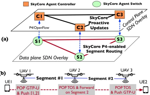
C1 C2 C3 S1 S2 S3 SkyCore P4-enabled Segment Routing SkyCore Proactive Updates Contr ol Plan e SDN Overla y P4/OpenFlow
Data plane SDN Overlay
SkyCore Agent Controller SkyCore Agent Switch
UAV 1 UAV 2 UAV 3
Segment #1 Segment #2
POP GTP-U & Push [1,2]
POP TOS & Forward
on Segment 2 & Push GTP-UPOP TOS
UE1 UE2
(a)
(b)
Figure 2.13: (a) SkyCore’s network-wide control and data plane connectivity for LTE UAV net-works. (b) Example of our segment routing
2.5
Efficient Inter-Agent Communication
2.5.1 Scalable SDN Control and Data Overlays
SkyCore agents seamlessly exchange control and data traffic with each other, a functionality that is lacking in today’s EPC instances. We leverage SDN overlays to create two virtualized network layers (slices) on top of the physical UAV network (Figure 2.13). One of these network slices is used for control plane traffic between SkyCore agents and the other is for data traffic. Our separation of the control and data traffic ensures time-critical control plane traffic is not affected when the network is saturated. To form the overlays, we use traffic tunneling technologies but depart from existing approaches used in EPC and datacenter (DC) networking [85, 83] since they require frequent changes to the network configuration (discussed shortly). We adopt a variant of segment-based routing in SkyCore and propose a design for its optimization based on the P4 language [60], thereby allowing operators to define new packet headers for SDN switches.
Segment-based overlays equipped with global source routing. Tunneling:We inter-connect each pair ofneighboring(geographic proximity) agents using a tunnel defined with a label. Whenever, an agent decides to send control or data plane traffic to any other agent in the
network, it pushes a stack of labels onto the packets. The top-of-the-stack label corresponds to the next tunnel segment the packet must traverse. Whenever an agent receives a packet from its neighbor, it checks the TOS label from the packet and forwards the packet based on the inner label to its neighbor. There is a master that is responsible for computing the label stack that each agent must use to communicate with the other agents. Instead of adding separate MPLS packet headers for each label, SkyCore designs a new packet header based on the P4 language to containallthe labels in the stack to reduce overhead. It equips switches with new actions to read the labels at different positions. Routing:In SkyCore, one of the UAVs is selected (periodically) to double up as a master agent that is responsible for global route computation. It periodically collects information from other agents, related to average loss rate and bandwidth on wireless links between different agents (UAVs), remaining battery capacity on UAVs, and the amount of traffic demand between different UAVs. The master agent uses this information to compute and disseminate forwarding rules for routing traffic over the UAV mesh backhaul in the sky.Proximity-based segments enable scalability:Note that UAV and UE mobility are common in our environment. Hence, a conventional EPC approach of establishing per-UE tunnels (GTP-U tunnels) will require frequent tunnel updates (tear down, modification, or set up). Similarly, employing a tunnel between every pair of UAV agents (akin to remote DC-DC tunnels) will require updates to a large fraction of the tunnels, even when only a small number of UAVs move. In contrast, most of SkyCore’s tunnel segments do not change in such scenarios as they are designed to carry aggregate traffic only between nearby pair of UAVs.
2.5.2 Proactive Stateless Mobility Support
SkyCore replaces the notion of centralized HSS and PCRF with precomputed policy data store replicated at different agents. Hence, it is essential that the UE states and policies are consistent across different agents, particularly during UE mobility. Reactive approaches to consistency management e.g., Distributed hash table (DHT) [120], put wireless (inter-UAV