APPLICATION OF ARTIFICIAL NEURAL NETWORK TO CLASSIFY FUEL OCTANE NUMBER USING ESSENTIAL ENGINE OPERATING
PARAMETERS
ALI GHANAATI
A thesis submitted in fulfilment of the requirements for the award of the degree of Doctor of Philosophy (Mechanical Engineering)
Faculty of Mechanical Engineering Universiti Teknologi Malaysia
DEDICATION
ACKNOWLEDGEMENT
I heartily express my gratefulness to Allah s.w.t for His blessing and strength that He blessed to me during the completion of this research.
My sincere thanks go to my supervisor Assoc. Prof. Dr. Intan Zaurah Mat Darus for her continuous motivation, constant advice, encouragement and support from start to the completion of my studies. I would also like to thank my co-supervisor Dr. Mohd Farid Muhamad Said for helping me to overcome the numerous technical challenges during my Ph.D. work.
My sincere thanks are also directed to the support staff of Automotive Development Centre (ADC), Mr. Mohd Rozi Mohd Perang, Mr. Hishammudin Mohd Jamil, Mr. Mohd Nazri Misseri and also Mr. Ahmad Solehin for their technical assistance throughout the entire period of the experimental work.
I am ever grateful to my family, especially my wife, for their continuous support in term of encouragement and motivation.
ABSTRACT
Real-time fuel octane number classification is essential to ensure that spark ignition engines operation are free of knock at best combustion efficiency. Combustion with knock is an abnormal phenomenon which constrains the engine performance, thermal efficiency and longevity. The advance timing of the ignition system requires it to be updated with respect to fuel octane number variation. The production series engines are calibrated by the manufacturer to run with a special fuel octane number. Presently, there is no research which takes into account the fuel tendency to knock in real-time engine operation. This research proposed the use of on-board detection of fuel octane number by implementing a simple methodology and use of a non-intrusive sensor. In the experiment, the engine was operated at different speeds, load, spark advance and consumed commercial gasoline with research octane numbers (RON) 95, 97 and 100. The RON classification procedure was investigated using regression analysis as a classic pattern recognition methodology and artificial neural network (ANN) by executing combustion properties derived from in-cylinder pressure signal and engine rotational speed signal. The in-cylinder pressure analysis illustrated the knock-free, light-knock and heavy-knock regions for all engine operating points. The results showed a special pattern for each fuel RON using peak in-cylinder pressure, maximum rate of pressure rise and maximum amplitude of pressure oscillations. Besides, there is a requirement for pre-defined threshold or formula to restrict the implementation of these parameters for on-board fuel identification. The ANN model efficiency with pressure signal as network input had the highest accuracy for all spark advance timing. However, the ANN model with rotational speed signal input only had the ability to identify the fuel octane number after a specific advance timing which was detected at the beginning of noisy combustion due to knock. The confusion matrix for the ANN with speed signal input had increased from 68.1% to 100% by advancing the ignition from -10° to -30° before top dead centre. The results established the ability of rotational speed signal for fuel octane classification using the relation between knock and RON. The implication is that all the production spark ignition engines are equipped with engine speed sensor, thus, this technique can be applied to all engines with any number of cylinders.
ABSTRAK
Masa sebenar klasifikasi nombor oktana bahan api adalah penting untuk memastikan operasi enjin pencucuhan percikan adalah bebas daripada ketukan pembakaran yang efisien. Pembakaran dengan ketukan adalah satu fenomena yang tidak normal yang mengekang prestasi enjin, kecekapan haba dan jangka hayat. Masa awal daripada sistem penyalaan memerlukan ia dikemas kini berdasarkan variasi nombor oktana bahan api. Enjin siri pengeluaran ditentukur oleh pengilang untuk beroperasi dengan nombor oktana bahan api khas. Pada masa ini, tidak ada penyelidikan yang mengambil kira kecenderungan bahan api untuk ketukan semasa enjin operasi. Kajian ini mencadangkan pengesanan penggunaan ofon-lembaga nombor oktana bahan api dengan melaksanakan kaedah yang mudah dan penggunaan sensor yang tidak mengganggu. Dalam eksperimen ini, enjin beroperasi pada kelajuan yang berbeza, beban, menganjakkan percikan berdasarkan petrol komersial dengan nombor penyelidikan oktana (RON) 95, 97 dan 100. Prosedur klasifikasi RON telah dikaji dengan menggunakan analisis regresi sebagai satu kaedah pengiktirafan corak klasik dan rangkaian neural buatan (ANN) dengan melaksanakan ciri-ciri pembakaran yang diperoleh daripada isyarat tekanan dalam silinder dan isyarat kelajuan putaran enjin. Analisis tekanan dalam silinder digambarkan berdasarkan kawasan ketukan bebas, ketukan kecil dan ketukan kuat pada semua kondisi operasi enjin. Hasil kajian menunjukkan satu corak khas bagi setiap bahan api RON yang menggunakan tekanan dalam silinder, kenaikan tekanan pada kadar maksimum dan ayunan tekanan pada amplitud maksimum. Selain itu, terdapat keperluan untuk ambang atau formula yang telah ditetapkan untuk menyekat pelaksanaan parameter ini untuk mengenal pasti bahan api sebenar. Kecekapan model ANN dengan isyarat tekanan sebagai input rangkaian mempunyai ketepatan tertinggi untuk semua pemasaan awal percikan. Walau bagaimanapun, model ANN dengan isyarat putaran input kelajuan hanya mempunyai keupayaan untuk mengenal pasti nombor oktana bahan api selepas menganjakkan pemasaan yang spesifik yang telah menyebabkan permulaan untuk pembakaran yang bising berpunca daripada ketukan. Matriks kekeliruan bagi ANN dengan input isyarat kelajuan telah meningkat dari 68.1% kepada 100% dengan menganjakkan pencucuhan dari -10 ° hingga -30 ° sebelum titik mati atas. Keputusan menunjukkan keupayaan isyarat kelajuan putaran untuk pengelasan oktana bahan api menggunakan hubungan antara ketukan dan RON. Implikasinya adalah bahawa semua enjin pengeluaran cucuhan percikan dilengkapi dengan isyarat kelajuan enjin, dengan itu, teknik ini boleh digunakan untuk semua enjin tanpa mengira bilangan silinder.
TABLE OF CONTENT
CHAPTER TITLE PAGE
DECLARATION ii
DEDICATION iii
ACKNOWLEDGEMENT iv
ABSTRACT v
ABSTRAK vi
TABLE OF CONTENT vii
LIST OF TABLES xi
LIST OF FIGURES xiii
LIST OF ABBREVIATIONS xix
LIST OF APPENDICES xxiv
1 INTRODUCTION 1
1.1 Foreword 1
1.2 Background 3
1.3 Statement of the Problem 5
1.4 Hypothesis 6
1.5 Objectives of the Research 6
1.6 Scope of the Research 7
1.7 Significance and Contribution of the Research 8
2 LITERATURE REVIEW 11
2.1 Introduction 11
2.2 Parameters Affecting Spark Ignition Timing 12 2.2.1 Laminar and Turbulent Flame Speed 13
2.3 Engine Knock Indicators 16
2.3.1 Knock Onset 17
2.3.2 Time-domain Metrics 18
2.3.3 Frequency-domain Metrics 19
2.4 Knock Detection Methods 20
2.4.1 Knock Detection Using In-cylinder Pressure Signal 20 2.4.2 Knock Detection Using Ionization Current Sensor 25 2.4.3 Knock Detection Using Exhaust Gas Temperature
Signal 26
2.4.4 Knock Detection Using Engine Vibrational Signals 28 2.5 Combustion Process Control Using Artificial Intelligent
Techniques 31
2.5.1 Expert Systems 31
2.5.2 Artificial Neural Network 31
2.5.3 Structure of Artificial Neural Network 34
2.5.4 Genetic Algorithm 39
2.5.5 Fuzzy Logic 40
2.5.6 Hybrid Systems 41
2.6 Estimation of Engine Maps 42
2.6.1 Model-based Advanced Ignition Control 44 2.7 The Relation between Knock Events and Surface Ignition
Phenomena 45
2.8 Fuel Octane Number Effect on Knock 46 2.9 The Instantaneous Crankshaft Speed 49
2.10 Research Gaps 50
2.11 Concluding Remarks 51
3 EXPERIMENTAL SETUP AND PROCEDURES 54
3.1 Introduction 54
3.2 The Test Engine 54
3.3 Instrumentation 55
3.3.1 Engine Management System 57
3.3.2 Lambda Meter 58
3.3.4 Engine Systems Temperature and Pressure
Measurement 59
3.3.5 Data Acquisition System 61
3.3.6 Crank Angle Encoder 63
3.3.7 Dynamometer 64
3.4 Knock Event Monitoring 65
3.4.1 In-cylinder Pressure Measurement 65
3.4.2 Standalone Knock Module 68
3.5 Experimental Fuel and Fuel Delivery System 69
3.6 Engine Operating Condition 72
3.6.1 Engine Test Procedure 72
3.7 Experimental Errors and Uncertainty 76
3.8 Experimental Limitations 76
3.9 Summary 77
4 ANALYSIS OF EXPERIMENTAL AND SIMULATION RESULTS 78
4.1 Introduction 78
4.2 Experimental Results 78
4.2.1 Resonant Frequencies Due to Knock Events 79
4.2.2 Spark Timing Sweep Results 83
4.2.3 Knock Intensity Determination 86
4.3 Simulation Results 100
4.3.1 1-dimensional Engine Model 100
4.3.2 Engine Combustion Sub-models 102
4.3.3 Design of Experiment 106
4.3.4 Knock Index Result for Different Fuel Octane
Numbers 108
4.3.5 Knock Index Results for Different Engine Loads 109 4.3.6 Knock Index Results for Different Engine Speeds 109
4.4 Summary 110
5 DIGITAL SIGNAL PROCESSING AND FUEL
CLASSIFICATION 112
5.2 Evaluation of the Combustion Parameters for Fuel Octane
Number Estimation 113
5.3 Analysis of Derivate Parameters from In-Cylinder Pressure 113 5.3.1 Mean Value of in-cylinder pressure signal 114 5.3.2 Peak In-cylinder Pressure Analysis 115
5.3.3 The Rate of Pressure Rise 117
5.3.4 MAPO Analysis 118
5.4 Analysis of Rotational Speed Signal 120 5.4.1 Pressure Signal Reconstruction Using Speed Signal 122 5.5 Fuel Octane Number Classification Using Artificial Neural
Network 123
5.5.1 The RON Identifier Using In-cylinder Pressure
Signal 124
5.5.2 The RON Identifier Using Engine Rotational Speed
Signal 129
5.6 Summary 133
6 CONCLUSIONS AND RECOMMENDATIONS FOR
FUTURE WORK 134
6.1 Conclusions 134
6.2 Recommendations for Future Work 136
REFERENCES 137 Appendices A-J 152 - 181
LIST OF TABLES
TABLE NO. TITLE PAGE
2.1 Summarized literature for knock detection methods 30
2.2 Using AI techniques for engine advance timing control 43
2.3 Using model based methods for engine parameter control 45
3.1 Proton CAMPRO-IAFM engine specifications 55
3.2 Gasoline specifications [171] 70
3.3 Experimental set-up procedure to test for one condition; fuel type =RON95, engine speed=2500 RPM,
brake torque=76 Nm and 1 74
3.4 Test points matrix 75
4.1 Calculated frequencies and vibration modes for right
circular cylinder 79
4.2 Results for resonate frequency of knock events using
different approaches 81
4.3 Combustion parameters due to spark advance variation
(N=2500 RPM, 76 Nm, and RON100) 86
4.4 MAPOth values at 2500 RPM, RON100, different loads,
and spark advance 91
4.5 Monitoring the knock ping sound at 2500 RPM, 76 Nm, and different RONs and spark advance (0=knock-free and
1=audible knock) 98
4.6 Initial combustion chamber parts temperature 105 4.7 The combustion properties results from simulation and
experimental, 2500 RPM, RON 95, brake torque = 76 Nm,
and SA = 30° bTDC 105
4.8 Parameter set up for full factorial DoE 108
5.1 The Pmax pattern for 250 consecutive cycles at 2500 RPM,
76 Nm, and SA=-30° bTDC 117
5.2 The dPmaxpattern for 250 consecutive cycles at 2500 RPM,
76 Nm, and SA=-30° bTDC 117
5.3 The MAPO pattern for 250 consecutive cycles at 2500 RPM,
76 Nm, and SA=-30° bTDC 119
5.4 Neural network characteristics 123
5.5 Experiment condition for identification the fuel octane number 124
5.6 The performance indexes of ANN model with pressure signal as network inputs at variable spark timing 129
5.7 The performance indexes of ANN model with speed signal as
LIST OF FIGURES
FIGURE NO. TITLE PAGE
1.1 Research procedure flowchart 10
2.1 The ion current signal and integral position [31] 26
2.2 The relation between EGT and spark advance [88] 27
2.3 Different layers of a feedforward neural network 35
2.3 Basic structure of FL controller 41
3.1 Schematic diagram of sensor and actuator locations
on the engine 56
3.2 An overview of engine test rig instrumentation and data
transmission 56
3.3 (a) The programmable ECU MOTEC type M400, lambda module, knock module, and UTC adapter (b) MOTEC
software environment 57
3.4 (a) Lambda meter (MOTEC PLM) and (b) the Bosch LSU 4 oxygen sensor installation location 59
3.5 Location of thermocouples on exhaust runner collector, O2
sensor, and pressure probe for collector pressure transducer 60
3.6 (a) Omega PX209 series hardware and (b) its wiring diagram 61
3.7 Data acquisition system type (a) NI SCB-68A and (b) NI 9213 61
3.8 (a) Block diagram of sensors and DAQs (b) front panel for
monitoring the pressure and temperature 62
3.9 Kistler crank angle encoder type 2613B (a) installation
3.10 Eddy-current dynamometer (DYNO-mite) 65
3.11 (a) Piezoelectric type in-cylinder pressure transducer type
601A and (b) DEWE-5000 combustion analyser 66
3.12 In-cylinder pressure transducer installation position 66
3.13 The flowchart for calculating the knock intensity for each
engine operating point 68
3.14 Installation position of the vibration type knock sensor and
audible knock detection system data communication overview 69
3.15 (a) schematic diagram of fuel path (b) ONO SOKKI type
FP-224 fuel flow meter display device and measuring device 70
3.16 The full set up of research test rig 71
3.17 The Proton CAMPRO maximum brake torque and related
spark timing [173] 73
4.1 Amplitude spectrum of in-cylinder pressure signal
(2500 RPM, 76 Nm, RON 97, and SA=-30° bTDC) 80
4.2 Frequency spectrogram in GoldWave (2500 RPM,
76 Nm, RON 97, and spark advance (SA)=-30° bTDC) 81
4.3 The original and band-pass filtered pressure signals
(2500 RPM, 76 Nm, RON97, and SA=-10° bTDC) 82
4.4 The original and band-pass filtered pressure signals
(2500 RPM, 76 Nm, RON97, and SA=-30° bTDC) 83
4.5 Location of the combustion phasing on a pressure trace (RON97, 2000 RPM, Torque = 76 Nm, and
spark advance (SA)=-20° bTDC) 84
4.6 In-cylinder pressure signal at different spark advances
(2500 RPM, 76 Nm, and RON100) 85
4.7 Location of CA50 for an operating point with 2500 RPM,
4.8 Three types of in-cylinder pressure signals (2000 RPM,
RON97, 76 Nm, SA=-15, SA=-20 , and SA=-25) 87
4.9 MAPO values for 250 cycles (2500 RPM, RON95,
51 Nm, SA=-45) 88
4.10 Cumulative frequency distribution for 2500 RPM, RON95, 76 Nm, and at different spark advance sweep
(-25, -30 and -35° bTDC) conditions 90
4.11 95th percentile of MAPO for 2500 RPM, RON95,
different loads, and spark advances 91
4.12 95th percentile of MAPO for 2500 RPM, RON97,
different loads, and spark advances 92
4.13 95th percentile of MAPO for 2500 RPM, RON100,
different loads, and spark advances 92
4.14 Knock intensity for 2500 RPM, RON95, variable loads,
and spark advances 93
4.15 Knock intensity for 2500 RPM, RON97, variable loads,
and spark advances 94
4.16 Knock intensity for 2500 RPM, RON100, variable loads,
and spark advances 94
4.17 Knock intensity for 1500 RPM, RON100, variable loads,
and spark advances 95
4.18 Knock intensity for 2000 RPM, RON100, different loads,
and spark advances 96
4.19 Knock intensity for RON100, 60% of maximum brake
torque load at different spark advances 96
4.20 Knock intensity for RON100, 2500 RPM, 60% of
maximum brake torque and variable spark advances 97
4.21 The envelope of cylinder block vibration signal for an engine operation point; 2500 RPM, 76 Nm, and RON95; (a) normal combustion with SA=-20° bTDC
and (b) combustion with knock with SA=-40° bTDC 99
4.22 Engine model structure in GT-Power 101
4.23 SolidWorks diagrams for geometrical calculations,(a) cylinder head and (b) piston cup of the Proton CAMPRO engine 102
4.24 The in-cylinder pressure traces for an engine operation point for test and simulation (2500 RPM, RON 95,
brake torque = 76 Nm, and SA=-30° bTDC) 106
4.25 A 3-D parameter space for full factorial design 107
4.26 Knock index for constant speed and load (2500 RPM
and 76 Nm) with different RON and spark advances 108
4.27 Knock index for RON95 and 2500 RPM engine speed with
different engine loads and spark advances 109
4.28 Knock index for RON95 and constant load (60% of maximum brake torque) with different engine speeds and
spark advances 110
5.1 In-cylinder pressure signals for 250 consecutive cycles,
2500 RPM, 76 Nm, RON95, and SA=-30° bTDC 114
5.2 The average of 250 consecutive cycle, =50.87 (bar) for RON95, =49.93 (bar) for RON 97, =49.15 (bar) for
RON100, (2500 RPM, 76 Nm and SA=-30° bTDC) 115
5.3
P
max values for 250 consecutive cycles for three differentRONs, 2500 RPM, 76 Nm, and SA=-30° bTDC 116
5.4 The sorted Pmax values for 250 cycles for three different
RONs, 2500 RPM, 76 Nm, and SA=-30° bTDC 116
5.5 dPmaxvalues for 250 cycles for three different RONs, 2500
RPM, 76 Nm, and SA=-30° bTDC 118
5.6 The MAPO values for 250 consecutive cycles for three
different RONs, 2500 RPM, 76 Nm, and SA=-30° bTDC 119
RONs, 2500 RPM, 76 Nm, and SA=-30° bTDC 120
5.8 Engine rotational speed signals for 250 consecutive cycles,
2500 RPM, 76 Nm, RON95, and SA=-30° bTDC 121
5.9 A noisy engine rotational speed signal before and after applying Savitzky-Golay filter; 2500 RPM, 76 Nm, RON95,
and SA=-30° bTDC 121
5.10 An in-cylinder pressure speed signal and related engine rotational speed signal; 2500 RPM, 76 Nm, RON95,
and SA=-30° bTDC 122
5.11 Network performance; 2500 RPM, 76 Nm, RON95,
and SA=-30° bTDC 123
5.12 Neural network with a general feed-forward topology and the hidden and output units associated with a
bias parameter 125
5.13 The in-cylinder pressure signal as the network input and the fuel RON as the network output, 2500 RPM,
76 Nm, and SA=-30° bTDC 125
5.14 The confusion matrix plot; class 1=RON95, class 2=RON97 and class 3=RON100 at 2500 RPM, 76 Nm,
and SA=-10° bTDC 126
5.15 The cross entropy function result for condition with
76 Nm and SA=-10° bTDC 127
5.16 The confusion matrix plot; class 1=RON95, class 2=RON97 and class 3=RON100 at 2500 RPM, 76 Nm,
and SA=-30° bTDC 128
5.17 The cross entropy function result for condition with 76 Nm and SA=-30° bTDC; best validation performance
is 6.0813e-7 at epoch 39 128
5.18 The instantaneous crankshaft rotational speed as the network input and the fuel RON as the network output,
2500 RPM, 76 Nm, and SA=-30° bTDC 130
5.19 The cross entropy function result for condition with 76 Nm and SA=-10° bTDC, best validation performance
is 0.061793 at epoch 14 130
5.20 The confusion matrix plot; class 1=RON95, class 2=RON97 and class 3=RON100 at 2500 RPM, 76 Nm,
and SA=-10° bTDC 131
5.21 The confusion matrix plot; class 1=RON95, class 2=RON97 and class 3=RON100 at 2500 RPM, 76 Nm,
and SA=-30° bTDC 132
5.22 The cross entropy function result for condition with 76 Nm and SA=-30° bTDC, best validation
LIST OF ABBREVIATIONS
aTDC - After Top Dead Center
AC Alternating Current
AI - Artificial Intelligence ANN - Artificial Neural Network
ARMA Auto Regressive Moving Average BMEP Brake Mean Effective Pressure BP - Back Propagation
BSFC Brake Specific Fuel Consumption bTDC - Before Top Dead Center
CAD - Crank Angle Degree
CA50 - Crank Angle For 50% of Mass Fraction Burnt CA90 - Crank Angle For 90% of Mass Fraction Burnt CAx - Crank Angle For x% of Mass Fraction Burnt CFR - Cooperative Fuel Research (Engine)
CI - Compression Ignition (Engine) CNG - Compressed Natural Gas DAQ - Data Acquisition System DC Direct Current (Voltage) DoE - Design of Experiment DSP Digital Signal Processing DWT Discrete Wavelet Transform
E85 - A fuel with 85% Ethanol and 15% gasoline ECU - Electronic Control Unit
EGR - Exhaust Gas Recirculation EGT - Exhaust Gas Temperature FFT Fast Fourier Transform
FRF Frequency Response Function GA - Genetic Algorithm
GUI - Graphical User Interface
HCCI - Homogeneous Charge Compression Ignition HIL Hardware in the Loop
ICE - Internal Combustion Engine IMEP - Indicated Mean Effective Pressure
KI - Knock Index
LKI Logarithmic Knock Intensity LOLIMOT - Local Linear Model Tree Networks LPG - Liquid Petroleum Gas
LPP - Location of Peak Pressure MAP - Manifold Air Pressure
MAHRO Maximum Amplitude of Heat Release Oscillation MAPO - Maximum Amplitude of Pressure Oscillation
MBT - Maximum Brake Torque or Minimum Spark Advance for Best Torque MFB - Mass Fraction Burned
MLP - Multi-Layer Perceptron
MVM Mean Value Model
NOx - Oxides of Nitrogen
PI proportional and integral (controller) PLM - Professional Lambda Meter
PLRBF - Pseudo-Linear Radial Basis Function RBF - Radial Basis Function
PFI Port Fuel Injection
PLM - professional lambda meter Pmax - Peak In-cylinder Pressure RON - Research Octane Number RPM - Revolution Per Minute
SA - Spark Advance
SEHRO Signal Energy of Heat Release Oscillations SEPO Signal Energy of Pressure Oscillations SG Savitzky-Golay (Filter)
SI - Spark Ignition (Engine) SKM Standalone Knock Module TDC - Top Dead Center
TWC Three-Way Catalyst
TVE - Threshold Value Exceeded
UTC USB-to-CAN
ULSD Ultra Low Sulfur Diesel VVT - Variable Valve Timing
LIST OF SYMBOLS
A - Activation energy multiplier
e
A - Entrainment surface area at the edge of the flame front
1 2
f f
AEFD - Average energy of the heat release
i
a - Network real output
B - Cylinder bore
c - Speed of sound
max
dP - Rate of pressure rise
f - Frequency
, m n
f - Specific frequencies of the acoustic modes
I - Induction time integral
j
I - Knock intensity for cycle j
tot
I - Total energy intensity
IVC - Crank angle at intake valve closed KI - Knock index
KO Knock onset
M - Knock index multiplier
m - Numbers of circumferential pressures nodes
b
M - Burned mass
e
M - Entrained mass of the unburned mixture
mse Mean Square Error
cyc
N - Number of cycles
n
- Numbers of circumferential pressures nodesON - Fuel octane number
P - Knock induction time multiplier p - Average cylinder pressure
p - Filtered in-cylinder pressure signal
max
P - Peak in-cylinder pressure
ave
P - Pressure mean value
i
p - Instantaneous cylinder pressure
R2 R-squared
L
S - Laminar flame speed
t
S - Turbulent flame speed
T - Bulk unburned gas temperature
t
- Timeu
T - Instantaneous unburned gas temperature
i
t - Network-predicted output
V Cylinder volume
TDC
V - Cylinder volume at top dead center - Equivalence ratio
0
- Crank angle corresponding to the beginning of the window of calculation for MAPO
n m,
Corresponding wave numberu
- Unburned density
- Ratio of specific heat
- Lambda signal from oxygen sensor - Taylor microscale length
- Time constanti
- Induction time
LIST OF APPENDICES
APPENDIX TITLE PAGE
A The Standard ECU Schematic Wiring (Proton CAMPRO) and Modified Schematic Wiring for
Programmable ECU (MOTEC-M400) 152
B Wide Band Oxygen Sensor Specification - Bosch
type LSU 4 154
C Pressure Transducer Specifications and Calibration
Reports 157
D NI SCB-68A and NI USB-9162 Pin Diagrams 163
E Kistler Crank Angle Encoder Type 2613B 165
F Savitzky-Golay Filter MATLAB Codes 169
G In-Cylinder Pressure Sensor Calibration Report
and Specifications 170
H MOTEC SKM Knock Module 175
I ONO SOKKI Type FP-224 Fuel Flow Meter
Specifications 178
J Neural Network Model MATLAB Codes for Fuel
1 CHAPTER 1
1 INTRODUCTION
1.1 Foreword
Based on global statistics for passenger car production in 2012, more than 165,000 passenger cars were produced per day (60 million per year). Over one billion passenger cars are driven in the world today [1]. Passenger cars and all types of trucks use internal combustion engine as their power source. Such vehicles are able to travel on roads by converting chemical energy of various types of fuels during the combustion process to kinetic energy. Gasoline, gasoil, ethanol, compressed natural gas (CNG), and liquid petroleum gas (LPG) are general fuels used in internal combustion engine (ICE). Low efficiency and exhaust emissions produced during combustion process are the most damaging output of internal combustion engine. In spark ignition (SI) engines, the ideal cycle efficiency is between 56% and 61%, and in car production, just 14%-30% of the energy generated from the consumed fuel is used to drive the car. However, practical compression ignition (CI) engines work 30%-35% more efficiently than SI engines [2]. In the 1970's, electronic technologies were introduced to automobile system controllers and mechanical control systems were replaced with electronic type in SI engines [3]. The engine electronic control unit (ECU) does the same task for ignition system after removing the distributer and also ECU excites the electrical injectors which exchanging with engine carburettor. The use of electronic control system resulted in improving the fuel efficiency, emission reduction, and torque production [4]. The number of engine systems components and controllers increased due to improvement in fuel economy and emission reduction. In addition, legislation related to decreasing the amount of exhaust emission tightened.
Engine controllers regulated all combustion details to reduce accurately exhaust emission. The design process and the addition of any new systems to the engine increase the complexity and production cost. Systems such as variable valve timing (VVT), exhaust gas recirculation (EGR) and charge-boosting systems (i.e., supercharger, turbocharger, and intercooler) influence the in-cylinder charge composition. Complexities of combustion control increase by controller objectives such as fuel efficiency, emission reduction, misfire and knock detection. Distinguishing between effects of several parameters that influence the combustion process has become more difficult with the increased number of engine systems. Furthermore, fuel octane number variation and the introduction of new bio-fuel increase such complexity.
ECU of the SI engines has two main tasks: managing the fuel injection and managing spark ignition (or injection timing in CI engine). The engine ignition system task is to ignite the air-fuel mixture in the combustion chamber at the ignition timing with adequate energy. Ignition timing depends on several factors such as engine speed and load (by measuring the manifold air pressure), engine warm-up condition, and knock occurrence. For instance, by providing a rich mixture and retard ignition, the combustion continues into the exhaust system, resulting in speeding up the warm-up process of three-way catalyst (TWC). The early electronic ignition control system was an open-loop system that used a look-up table provided in engine test procedure with dynamometer. The ignition timing look-up table consisted of a matrix that considered required advance ignition for every engine speed and load. The benefit of this approach was to overcome the non-linearity of engine phenomena. In addition, engine ignition timing is affected by in-cylinder mixture properties. The fuel octane number, laminar flame speed, turbulent intensity, residual fraction, temperature, and equivalence ratio affect the ignition timing. Any change in these parameters requires that the look-up table data be updated to adjust the ignition to achieve maximum brake torque (MBT) timing [5].
A combustion closed-loop control system requires a feedback signal from combustion process and also uses look-up table as a reference for adjusting the ignition. It prevents the engine from operating in knock region by monitoring the vibration signal from a knock sensor installed on engine cylinder block. The controller
works as a closed-loop control system, and ignition timing is retarded when a knock event is detected. However, retard ignition reduces the combustion efficiency and engine works far from MBT timing [6].
1.2 Background
Ideally, nearly all of the fuel energy would be released in ICEs when the piston was at top dead centre (TDC) and ready to begin the power stroke. In SI engines with port fuel injection (PFI), the fuel is premixed with air before entering the combustion chamber and energy release begins when the spark plug is fired. Significant time is required for the flame front to progress from the spark plug to the far side of the combustion chamber; thus, the spark plug must be fired before TDC. Spark advance refers to the number of crankshaft degrees before TDC at which the spark plug fires. Because initial flame speed is nearly constant, greater spark advance is required at higher engine speeds to allow sufficient time for the flame front to cross the combustion chamber. The unstretched laminar burning velocity depends on fuel type and equivalence ratio, 33.3 cm/s for iso-octane and 38.9 cm/s for n-heptane at stoichiometric mixture. Greater spark advance is also required for leaner mixtures, because they burn more slowly than chemically correct mixtures. A lean mixture is one in which the fuel-to-air ratio is less than the chemically correct ratio [7]. The ignition control system target is to set the MBT timing at CA50 (crank angle which 50 percent of mixture burned); therefore, the spark advance strategy after this value or the occurrence of the audible knock should be stopped.
Ignition timing is one of the major factors that directly affects the combustion process. Combustion phasing, such as crank angle for the consumption of 50% of the fuel mass (CA50), crank angle for the consumption of 90% of the fuel mass (CA90), the duration from consumption of 10% to 90% of the air/fuel mixture (CA10-CA90 duration), and location of peak pressure (LPP), is influenced by advancing the ignition as the starting point of combustion. The general combustion phasing location is CA50, the point when 50% of in-cylinder mixture mass burned in crank angle degree (CAD). The indicated mean effective pressure (IMEP) is most relevant parameter in terms of engine efficiency and CA50 location defines the MBT timing point. Another definition
for MBT is "minimum spark advance for best torque", illustrating that ignition timing is restricted by knock phenomena. At MBT timing, the maximum acceleration point of mass fraction burned (MFB) is located at around top dead centre. The optimized CA50 is 8-10° aTDC, and the peak cylinder pressure location is around 15° aTDC. Consequently, the only requirement for handling the combustion into MBT timing is adjusting the ignition in such a way that CA50 can occur around 8-10° aTDC [8-9]. Therefore, the main target of combustion control designer for ignition advance timing is to set the CA50 at MBT timing [5,10].
To adjust the ignition on MBT location, look-up table (or map) based ignition control system is introduced. It is quite hard and time consuming to prepare the ignition timing map. However, it is easy to implement it on the engine ignition system. Since maps are developed in laboratory measurements, data are only acceptable for that condition, i.e., engine wearing and production tolerances decrease the control accuracy. Several parameters reduce or disable the map-based control system during the engine operation such as fuel octane number, engine subsystems alteration, environment variety, etc.
A look-up table structure consists of a matrix that defines the optimum ignition timing for each engine operation point with respect to manifold air pressure (MAP) and engine speed. A microprocessor serves to apply map data by receiving the engine speed and load signal from related sensors. Moreover, the correction for engine warm-up condition and torque reduction request from automobile stability system is applied during engine operation. Additionally, in a closed-loop map-based ignition control system, an extra correction has been done with respect to knock sensor signals for preventing repetitive knock events. A new window is opened for such system improvement by transition from mechanical system to map-based electronic system that conquered the engine non-linear phenomena.
SI engines consume a wide variety of fuel with different characteristics such as octane number and laminar flame speed, which directly affect the ignition timing. Gasoline, LPG, CNG, Hydrogen, and E85 (a blend of 85% ethanol and 15% gasoline) are common fuels commercially used in SI engines. Different burning rate and knock tendency increase the complexity of the ignition timing map; thus, an individual map for each fuel should be designed. In conclusion, an essential control algorithm capable
of detecting and predicting the properties of fuel with respect to fuel efficiency and emission reduction is required. For introducing a new control algorithm for real-time ignition adjustment, knock and misfire limitation, MBT settles, and emission reduction should be taken into account. By implementing the model-based spark advance controller, SI engines can work with a wide range of fuel octane number; an approach that improves the use of new energy sources and severely reduces the research cost for new fuel utilization. The overall cost of improving the octane number and fuel production process, essentially for bio-fuel, can be reduced by this approach. Therefore, the engine performance and efficiency can be enhanced when various types of fuel are applied.
1.3 Statement of the Problem
This research aims at finding a useful feed-back signal from combustion process for designing a closed-loop control system. The in-cylinder pressure measurement, using pressure transducer or ion current sensor, has been applied to several studies on knock detection. However, the complexity of signal analysis, high expense, low precision, and poor stability have limited the implementation of such controllers that use such signals. Furthermore, cylinder-to-cylinder variations have been ignored because the system needs individual combustion analysis for each cylinder. Several sample sets are needed to increase the accuracy in steady state condition, making it difficult to consider engine transient condition [11-15].
Numerous techniques have been adopted to reconstruct the cylinder pressure from the instantaneous crankshaft speed measurement [16-17]. The engine angular velocity and its derivative has been implemented as inputs in artificial neural network (ANN) to estimate the LPP [18], finding the correlation between torque and engine speed [19], instantaneous pressure estimation [20], IMEP estimation [21] and different diesel fuel identifier [22]. In this research, the engine rotational speed has been implemented as the input into an ANN to identify different fuel octane numbers. The objectives of an adaptive model-based ignition control system are to adjust the spark advance to locate the MBT timing on CA50 and to prevent knock occurrence or knock repetition at all engine operating conditions. Therefore, the main targets of this
research are to develop a neural network structure that is able to identify the fuel octane number and to determine the correction requirement for spark advance with a high degree of freedom related to variation in fuel properties and combustion chamber tendency to surface ignition.
1.4 Hypothesis
When the engine control unit technology evolves and when a new fuel is introduced to be used in an internal combustion engine, the most important issue is how to update the engine maps with new conditions. For instance, engines that simultaneously consume gasoline and CNG need two different spark timing look-up tables for each type of fuel. Furthermore, engine controllers need to be updated with current engine operation parameter; in other words, if the octane number is defined as a fixed parameter in the laboratory, the controller operation will be corrected for that situation and pump-to-pump fuel properties will be varied to enhance the engine efficiency.
Demand for high fuel efficiency and emission reduction has increased the demand for new engine actuators. VVT, EGR, and charge-boosting systems are the most popular and new technologies in SI engines [23-25]. The cost of implementing such systems is very high, which confines its application to engine. Therefore, a new approach for updating the control parameters during the engine operation is proposed in this research. This technique can detect any changes in the fuel properties or engine systems. While spark timing is the main issue in SI engines equipped with PFI system, the injection timing is the control parameter for CI engines. Similar to SI engines, CI engines can be reutilized via the proposed approach for their fuel injection timing.
1.5 Objectives of the Research
The present research mainly aims at utilizing a neural network structure for on-board identification of fuel octane number. The network has the ability to use an
operating parameter as the network input and the fuel octane number as the network output. The spark advance will be updated with regard to identification of the octane number. The specific objectives of this research are:
1) To investigate and validate the knock intensity for different fuel octane number at altered engine speed and load using in-cylinder pressure signal and cylinder block vibration signal.
2) To compare and validate the knock detection results using the experimental signals using knock prediction results obtained from GT-Power simulation software.
3) To investigate the engine operating parameter thus finding a reliable factor related to octane number variety.
4) To design and develop an ANN structure for fuel octane number identification using input-output data obtained experimentally.
1.6 Scope of the Research
The scope of this research is categorized into four items as follow:
1) Organization of test rig to run an SI engine at different speed and load with different fuels:
Modification of the engine harness and installation programmable ECU on a series production engine in order to adjust the injection duration and sweep the ignition timing;
Installation of in-cylinder pressure transducer and crank angle encoder to collect the experiment requirement for knock analysis.
2) To perform the test point considering:
The engine operation condition limited to low engine speed ranges (as knock intensity is high), the engine load increased from 20 to 60% of maximum brake torque with 20% interval;
The octane number of fuels used in this research is limited to RON95, RON97, and RON100 (representing research octane number (RON) for commercial gasoline);
The injection duration adjusted to operate the engine only at stoichiometric mixture along using a wide range oxygen sensor and a lambda module;
The spark timing is swept till audible knock region using a programmable ECU.
3) To carry out the testing results analysis:
Frequency analysis of in-cylinder pressure and cylinder block vibration signals to define the domain of acoustic resonance frequency due to knock events;
Comparison and validation of knock envelope extracted from in-cylinder pressure signal by cylinder block vibration signal;
Modelling and simulation of combustion process using the SI turbulent flame entrainment model and Douaud and Eyzat knock predictor model in GT-Power environment.
4) To design and develop a fuel identifier algorithm:
Comparative and statistical analysis of combustion parameters for different fuel octane number.
Comparative and statistical analysis of in-cylinder pressure signal and engine rotational speed signal as the input signal into a neural network structure to identify the fuel types (different RONs).
1.7 Significance and Contribution of the Research
The novelties of this research and test rig instrumentation are listed below:
1) Reliable parameter to identify the fuel octane number has been selected and validated using in-cylinder pressure signal and engine rotational speed.
2) An ANN model has been trained, validated, and tested for on-board fuel octane classification by monitoring the pattern of instantaneous rotational speed.
The other prospective contributions of this study include:
1) The knock boundary prediction for engine operating range utilizing the validated combustion model in GT-Power.
2) The knock intensity determination for different fuel octane numbers and illustration of the differences.
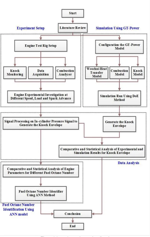
Figure 1.1 briefly presents the procedure of the study in four steps; experiment setup, simulation using GT-Power, data analysis, and fuel octane identifier using ANN.
6 REFERENCES
[1] OICA. The International Organization of Motor Vehicle Manufacturers. Prod Stat | OICA. 2015. Available: http://www.oica.net/category/production-statistics/.
[2] Fuel Economy. 2016. Available: http://www.fueleconomy.gov
[3] Winstead, W.P. A Production Computerized Engine Timing Control System. SAE Tech Pap. 1977.
[4] Prucka, R.G., Filipi, Z.S., and Assanis, D.N. Control-Oriented Model-Based Ignition Timing Prediction for High-Degrees-of-Freedom Spark Ignition Engines. Proc Inst Mech Eng Part D J Automob Eng. 2012. 226:828–39. [5] Caton, J.A. Combustion phasing for maximum efficiency for conventional and
high efficiency engines. Energy Convers Manag. 2014. 77:564–76.
[6] Russ, S., Lavoie, G., and Dai, W. SI Engine Operation with Retarded Ignition: Part 1 - Cyclic Variations. SAE Tech Pap. 1999.
[7] Takashi, H., Engineering, M., and Burning, L. Laminar flame speeds of ethanol,. Int Fed Automot Eng Soc Student Congr Pap. 2006.
[8] Wang, W., Chirwa, E.C., Zhou, E., Holmes, K., and Nwagboso, C. Fuzzy ignition timing control for a spark ignition engine. Proc Inst Mech Eng Part D-Journal Automob Eng. 2000. 214:297–306.
[9] Saraswati, S., Agarwal, P.K., and Chand, S. Neural networks and fuzzy logic-based spark advance control of SI engines. Expert Syst Appl. 2011. 38:6916– 25.
[10] Kaleli, A., Ceviz, M.A., and Erenturk, K. Controlling spark timing for consecutive cycles to reduce the cyclic variations of SI engines. Appl Therm Eng. 2015. 87:624–32.
of Spark Advance and Air-Fuel Ratio in SI Engines Using Cylinder Pressure. SAE Tech Pap. 2000.
[12] Zhu, G.G., Daniels, C.F., and Winkelman, J. MBT Timing Detection and its Closed-Loop Control Using In-Cylinder Ionization Signal Reprinted From : SI Engine Experiment and Modeling. SAE Tech Pap. 2003.
[13] Emiliano, P. Spark Ignition Feedback Control by Means of Combustion Phase Indicators on Steady and Transient Operation. J Dyn Syst Meas Control. 2014. 136:51021.
[14] Ettefagh, M.M., Sadeghi, M.H., Pirouzpanah, V., and Arjmandi Tash, H. Knock detection in spark ignition engines by vibration analysis of cylinder block: A parametric modeling approach. Mech Syst Signal Process. 2008. 22:1495–514. [15] Siano, D. and D’Agostino, D. Knock detection in SI engines by using the Discrete Wavelet Transform of the engine block vibrational signals. Energy Procedia. 2015. 81:673–88.
[16] Ali, S.A. and Saraswati, S. Reconstruction of cylinder pressure using crankshaft speed fluctuations. 2015 Int Conf Ind Instrum Control ICIC 2015. 2015. 37:456–61.
[17] Bennett, C., Dunne, J.F., Trimby, S., and Richardson, D. Engine cylinder pressure reconstruction using crank kinematics and recurrently-trained neural networks. Mech Syst Signal Process. 2017. 85:126–45.
[18] Taglialatela, F., Cesario, N., Lavorgna, M., Merola, S.S., and Vaglieco, B.M. Use of engine crankshaft speed for determination of cylinder pressure parameters. SAE Tech Pap. 2009.
[19] Ponti, F., Ravaglioli, V., Serra, G., and Stola, F. Instantaneous Engine Speed Measurement and Processing for MFB50 Evaluation. SAE Tech Pap. 2009. [20] Daniel Brand, Christopher H. Onder, and Lino Guzzella. Estimation of the
Instantaneous In-Cylinder Pressure for Control Purposes using Crankshaft Angular Velocity. SAE Techcnical Pap. 2005.
[21] Kallenberger, C., Hamedović, H., Raichle, F., Breuninger, J., Fischer, W., Benninger, K., et al. Estimation of Cylinder-Wise Combustion Features from Engine Speed and Cylinder Pressure. SAE Int. 2008.
SAE Int. 2014.
[23] Corti, E., Cavina, N., Cerofolini, A., Forte, C., Mancini, G., Moro, D., et al. Transient Spark Advance calibration approach. Energy Procedia. 2014. 45:967–76.
[24] Chen, L., Li, T., Yin, T., and Zheng, B. A predictive model for knock onset in spark-ignition engines with cooled EGR. Energy Convers Manag. 2014. 87:946–55.
[25] Galloni, E., Fontana, G., and Palmaccio, R. Effects of exhaust gas recycle in a downsized gasoline engine. Appl Energy. 2013. 105:99–107.
[26] SAE J1312. Procedure for Mapping Engine Performance - Spark Ignition and Compression Ignition Engines. 1995.
[27] Fontanesi, S., Severi, E., Siano, D., Bozza, F., and De Bellis, V. Analysis of Knock Tendency in a Small VVA Turbocharged Engine Based on Integrated 1D-3D Simulations and Auto-Regressive Technique. SAE Int. 2014.
[28] Harrington, J.A., Shishu, R.C., and Asik, J.R. A Study of Ignition System Effects on Power , Emissions , Lean Misfire Limit , and EGR Tolerance of a Single-Cylinder Engine - Multiple Spark versus Conventional Single Spark Ignition. SAE Tech Pap. 1974.
[29] Nates, R.J. and Yates, A.D.B. Knock Damage Mechanisms in Spark-Ignition Engines. SAE Tech Pap. 1994.
[30] Schweitzer, P.H. and Collins, T.W. Electronic Spark Timing Control for Motor Vehicles. SAE Tech Pap. 1978.
[31] Zhu, G.G., Haskara, I., and Winkelman, J. Closed-loop ignition timing control for SI engines using ionization current feedback. IEEE Trans Control Syst Technol. 2007. 15:416–27.
[32] Hassaneen, A.E. Prediction of Optimum Ignition Timing in a Natural Gas-Fueled Spark Ignition Engine Using Neural Network. Sae Tech Pap Ser. 2006. [33] Nallapa, V.R., Syed, F., Russell, J., Spiteri, R., Grytzelius, M., Grand, C., et al. Methods for Modeling and Code Generation for Custom Lookup Tables. SAE Int. 2010.
SAE Tech Pap. 1997.
[35] Brehob, D.D., Newman, C.E., and Co, F.M. Monte Carlo Simulation of Cycle by Cycle Variability. SAE Tech Pap. 1992.
[36] Sodré, J.R. A Parametric Model for Spark Ignition Engine Turbulent Flame Speed. SAE Tech Pap. 1998.
[37] Turns, S.R. An introduction to combustion: concepts and applications. vol. 499. Boston: McGraw-Hill book company; 2000.
[38] Fontana, G., Bozza, F., Galloni, E., and Siano, D. Experimental and Numerical Analyses for the Characterization of the Cyclic Dispersion and Knock Occurrence in a Small-Size SI Engine. Small Engine Technol Conf Expo. 2010. 2010-32–00.
[39] Suzuki, K., Nemoto, M., and Machida, K. Model-Based Calibration Process for Producing Optimal Spark Advance in a Gasoline Engine Equipped with a Variable Valve Train. SAE Tech Pap. 2006.
[40] Poulos, Stephen G. and Heywood, J.B. The Effect of Chamber Geometry on Spark-Ignition Engine Combustion. SAE Tech Pap. 1983.
[41] Mannaa, O., Mansour, M.S., Roberts, W.L., and Chung, S.H. Laminar burning velocities at elevated pressures for gasoline and gasoline surrogates associated with RON. Combust Flame. 2015. 162:2311–21.
[42] Ghanaati, A., Mat Darus, I.Z., Muhamad Said, M.F., and Mahmoudzadeh Andwari, A. A mean value model for estimation of laminar and turbulent flame speed in spark-ignition engine. Int J Automot Mech Eng. 2015. 11:2224–34. [43] Wang, S., Zhu, Q., Prucka, R., Prucka, M., and Dourra, H. Input Adaptation for
Control Oriented Physics-Based SI Engine Combustion Models Based on Cylinder Pressure Feedback. SAE Int J Engines. 2015.
[44] Beccari, S., Pipitone, E., and Genchi, G. Knock onset prediction of propane, gasoline and their mixtures in spark ignition engines. J Energy Inst. 2016. 89:101–14.
[45] Xavier, E.M.R.S., Westphal, R., and Rodrigues, W.N. Reduction of Experimental Data Points in the Base Calibration by Estimation of Engine Maps Using Regularized Basis Function Neural Networks. SAE Tech Pap. 2012.
[46] Hudson, C., Gao, X., and Stone, R. Knock measurement for fuel evaluation in spark ignition engines. Fuel. 2001. 80:395–407.
[47] Shahlari, A.J. and Ghandhi, J.B. A Comparison of Engine Knock Metrics. SAE Tech Pap. 2012.
[48] Davis, R.S. and Patterson, G.J. Cylinder Pressure Data Quality Checks and Procedures to Maximize Data Accuracy in Thermal Fluid Sciences 2006. SAE Tech Pap. 2006.
[49] Worret, R., Bernhardt, S., Schwarz, F., and Spicher, U. Application of Different Cylinder Pressure Based Knock Detection Methods in Spark Ignition Engines Reprinted From : SI Engine Experiments. SAE Tech Pap. 2002. 2002-01–16. [50] Abu-Qudais, M. Instantaneous Exhaust-Gas Temperature and Velocity for a
Diesel Engine. Appl Energy. 1997. 56:59–70.
[51] Ollivier, E., Bellettre, J., and Tazerout, M. A Non Intrusive Method for Knock Detection Based on the Exhaust Gas Temperature. SAE Tech Pap. 2005. [52] Sayin, C. The impact of varying spark timing at different octane numbers on the
performance and emission characteristics in a gasoline engine. Fuel. 2012. 97:856–61.
[53] Eng, J.A. Characterization of Pressure Waves in HCCI Combustion. SAE Tech Pap. 2002.
[54] Heywood, J.B. Internal Combustion Engine Fundamental. New York: McGraw-Hill; 1988.
[55] Vulli, S., Dunne, J.F., Potenza, R., Richardson, D., and King, P. Time-frequency analysis of single-point engine-block vibration measurements for multiple excitation-event identification. J Sound Vib. 2009. 321:1129–43.
[56] Checkel, M.D. and Dale, J.D. Testing a Third Derivative Knock Indicator on a Production Engine. SAE Tech Pap. 1986.
[57] Shu, G., Pan, J., and Wei, H. Analysis of onset and severity of knock in SI engine based on in-cylinder pressure oscillations. Appl Therm Eng. 2013. 51:1297–306.
[58] Cavina, N., Corti, E., Minelli, G., Moro, D., and Solieri, L. Knock Indexes Normalization Methodologies. SAE Int. 2006.
[59] Zavala, J.C. and Folkerts, C. Knock Detection and Estimation Based on Heat Release Strategies. SAE Int. 2011.
[60] Xiaofeng, G., Stone, R., Hudson, C., and Bradbury, I. The Detection and Quantification of Knock in Spark Ignition Engines. SAE Tech Pap. 1993. [61] Puzinauskas, P. V. Examination of Methods Used to Characterize Engine
Knock. SAE Tech Pap. 1992.
[62] Rahmouni, C., Brecq, G., Tazerout, M., and Le Corre, O. Knock rating of gaseous fuels in a single cylinder spark ignition engine. Fuel. 2004. 83:327–36. [63] Millo, F. and Ferraro, C. V. Knock in S.I. Engines: A Comparison between
Different Techniques for Detection and Control. SAE Tech Pap. 1998.
[64] Zhen, X., Wang, Y., Xu, S., Zhu, Y., Tao, C., Xu, T., et al. The Engine Knock Analysis – An Overview. Appl Energy. 2012. 92:628–36.
[65] Daniels, C.F., Zhu, G.G., and Winkelman, J. Inaudible Knock and Partial-Burn Detection Using In-Cylinder Ionization Signal. SAE Tech Pap. 2003.
[66] Fleming, W.J. Overview of Automotive Sensors. IEEE Sens J. 2001. 1:296– 308.
[67] Wang, W., Chirwa, E.C., Zhou, E., Holmes, K., and Nwagboso, C. Fuzzy Neural Ignition Timing Control for a Natural Gas Fuelled Spark Ignition Engine. Proc Inst Mech Eng. 2001. 215:1311–23.
[68] Müller, R., Hart, M., Krötz, G., Eickhoff, M., Truscott, A., Noble, A., et al. Combustion Pressure Based Engine Management System. SAE Tech Pap. 2000. [69] Müller, R. and Hemberger, H. Neural Adaptive Ignition Control. Sae Tech Pap.
1998.
[70] Checkel, M.D. and Dale, J.D. Pressure Trace Knock Measurement in a Current S.I. Production Engine. SAE Tech Pap. 1989.
[71] Ando, H., Takemura, J., and Koujina, E. A Knock Anticipating Strategy Basing on the Real-Time Combustion Mode Analysis. SAE Tech Pap. 1989.
[72] Spelina, J.M., Peyton Jones, J.C., and Frey, J. Recent Advances in Knock Analysis, Simulation, and Control. SAE Int. 2014.
[73] Burgdorf, K. and Denbratt, I. Comparison of Cylinder Pressure Based Knock Detection Methods. SAE Tech Pap. 1997.
[74] Siano, D., Panza, M.A., and D’Agostino, D. Knock Detection Based on MAPO Analysis, AR Model and Discrete Wavelet Transform Applied to the In-Cylinder Pressure Data: Results and Comparison. SAE Int J. 2014.
[75] Scholl, D., Davis, C., Russ, S., and Barash, T. The Volume Acoustic Modes of Spark-Ignited Internal Combustion Chambers. SAE Tech Pap. 1998.
[76] Leppard, W.R. Individual-Cylinder Knock Occurence and Intensity in Multicylinder Engines. SAE Tech Pap. 1982.
[77] Galloni, E. Dynamic knock detection and quantification in a spark ignition engine by means of a pressure based method. Energy Convers Manag. 2012. 64:256–62.
[78] Ausserer, J.K., Rowton, A.K., Grinstead, K.D., Litke, P.J., and Polanka, M.D. Comparison of In-Cylinder Pressure Measurement Methods in a Small Spark Ignition Engine. SAE Tech Pap. 2014.
[79] Evers, L.W. Spark Plug Pressure Transducers For Measuring Indicated Work. SAE Tech Pap. 1978.
[80] Szwaja, S., Bhandary, K.R., and Naber, J.D. Comparisons of hydrogen and gasoline combustion knock in a spark ignition engine. Int J Hydrogen Energy. 2007. 32:5076–87.
[81] Prucka, R.G., Lee, T.-K., Filipi, Z., and Assanis, D. Turbulence Intensity Calculation from Cylinder Pressure Data in a High Degree of Freedom Spark-Ignition Engine. SAE Int. 2010.
[82] Docquier, N. and Candel, S. Combustion control and sensors: A review. Prog Energy Combust Sci. 2002. 28:107–50.
[83] Zhen, X., Wang, Y., Xu, S., Zhu, Y., Tao, C., Xu, T., et al. The Engine Knock Analysis – An Overview. Appl Energy. 2012. 92:628–36.
[84] Badawy, T., Shrestha, A., and Henein, N. Detection of Combustion Resonance Using an Ion Current Sensor in Diesel Engines. ASME 2011 Intern. Combust. Engine Div. Fall Tech. Conf., ASME; 2011, p. 755–63.
[85] Shamekhi, A.H. and Ghaffari, A. Fuzzy control of spark advance by ion current sensing. Proc Inst Mech Eng Part D-Journal Automob Eng. 2007. 221:335–42. [86] Morey, F. and Seers, P. Comparison of cycle-by-cycle variation of measured
exhaust-gas temperature and in-cylinder pressure measurements. Appl Therm Eng. 2010. 30:487–91.
[87] Enomoto, Y., Kitahara, N., and Takai, M. Heat Losses during Knocking in a Four-Stroke Gasoline Engine. JSME Int J Ser B. 1994. 37:668–76.
[88] Abu-qudais, M. Exhaust Gas Temperature for Knock Detection and Control in Spark Ignition Engine. Energy Convers Mgmt. 1996. 37:1383–92.
[89] Dues, S.M., Adams, J.M., Shinkle, G.A., and Div, D.R. Combustion Knock Sensing : Sensor Selection and Application Issues. SAE Tech Pap. 1990. [90] Thomas, J. and Dubuisson, B. Engine Knock Detection from Vibration Signals
using Pattern Recognition. Meccanica. 1997. 32:431–9.
[91] Siano, D., Bozza, F., Agostino, D.D., and Panza, M.A. The Use of Vibrational Signals for On-Board Knock Diagnostics Supported by In-Cylinder Pressure Analyses. SAE Int. 2014.
[92] Park, S.T. and Yang, J. Engine Knock Detection Based on Wavelet Transform. IEEE Control Syst Mag. 2004.
[93] Kalogirou, S.A. Artificial intelligence for the modeling and control of combustion processes: A review. Prog Energy Combust Sci. 2003. 29:515–66. [94] Xu, M., Azevedo, J.L.T., and Carvalho, M.G. Modeling of a front wall fired
utility boiler for different operating conditions. Comput Methods Appl Mech Eng. 2001. 190:3581–90.
[95] Nannariello, J. and Fricke, F. Introduction to Neural Network Analysis and its Application to Building Services Engineering. Build Serv Eng Res Technol. 2001. 22:58–68.
[96] Tasdemir, S., Saritas, I., Ciniviz, M., and Allahverdi, N. Artificial neural network and fuzzy expert system comparison for prediction of performance and emission parameters on a gasoline engine. Expert Syst Appl. 2011. 38:13912– 23.
[97] Kalogirou, S. a. Applications of artificial neural-networks for energy systems. Appl Energy. 2000. 67:17–35.
[98] Kalogirou, S. a. Artificial neural networks in renewable energy systems applications: a review. Renew Sustain Energy Rev. 2001. 5:373–401.