Acoustic-Based Electrodynamic Energy
Harvester for Wireless Sensor Nodes Application
Farid Ullah Khan and Izhar
Institute of Mechatronics Engineering, University of Engineering and Technology, Peshawar, Pakistan Email: {dr_farid_khan, 09pwmct0063}@nwfpuet.edu.pk
Abstract—An electrodynamic harvester for scavenging acoustic energy is reported in this paper. The working principle, fabrication and characterization of the harvester are discussed. The developed harvester consists of an Helmholtz resonator, flexible membrane, moving magnets and a fixed wound coil. The harvester is characterized under acoustic energy at different sound pressure levels (SPL’s) and is subjected to both increasing frequency sweep (IFS) and decreasing frequency sweep (DFS). At resonance and under 120 dB SPL, the harvester produced a maximum load rms voltage of 315 mV at 66 Ω load resistance. The experimental results showed the maximum power delivered to load is 1503.4 μW at 120 dB SPL, that leads to a maximum power density of 191.4 μW/cm3 for the developed harvester. The energy harvester is also characterized in open air with a large speaker as an acoustic source. Moreover, the harvester generated a load voltage of about 30 mV when subjected to the acoustical noise of a household electrical generator.
Index Terms—acoustic energy, electrodynamics, energy harvesting, Helmholtz resonator, nonlinear response
I. INTRODUCTION
In recent years, with the rapid development in technology, the application of wireless sensors has immensely increased. The wireless sensors play an important role in remote intelligent sensing systems, such as, mobile survey robots, structural health monitoring [1], tire pressure and temperature monitoring system and condition monitoring of aircraft engines [2]. For the conversion of wireless sensors into autonomous sensors the main problem associated is the power source [3], [4]. The power requirement of the wireless sensor node is obtained from a battery. The battery finite life limits the application of wireless sensor nodes for remote, embedded, hazardous and harsh environments [5]. In the last decade, energy harvesting from the wireless sensor’s environment is employed to replace or supplement the battery power. The integration of micro energy harvester with wireless sensor will result in a long lasting autonomous sensor node. For the development of micro energy harvester, several ambient energies are available in wireless sensor’s surroundings, such as, solar, wind, vibration and thermal. Likewise, these ambient energy
Manuscript received July 13, 2013; revised October 28, 2013.
sources, acoustic energy is also abundantly available in the surroundings of wireless sensor nodes. For wireless sensor nodes, the transduction of ambient acoustic energy into electrical energy is suitable for applications such as non-destructive health monitoring of machines (such as, turbines, rotary compressors, electrical generators and motors) and vehicles (automobiles and aircrafts). In the surrounding of the aircraft, the sound pressure level (SPL) above 80 dB is obtained over a frequency range of 20 Hz to 20 kHz [6]. In vehicles, such as automobiles, the SPL ranges from 70 dB to 90 dB over a frequency band that range from 1 to 100 Hz [7]. In the surrounding of the turbofan engines, the SPL of about 150 dB is obtained over a frequency range of 20 Hz to 20 kHz [8], [9]. Moreover, in automobiles without engine muffler, the SPL reaches up to 194 dB and its frequency is spread over a range of 1 to 20 Hz [10]. In car air conditioning system, acoustic energy exits, in supply duct, return duct and exhaust duct with SPLs that reaches up to 71.9, 65.1 and 47.7 dB respectively over a frequency range of 20 Hz to 20 kHz [11].
piezoelectric materials and sonic crystals is reported by [16]. At resonance maximum power is produced under a load resistance of 3.9 kΩ. At 4.2 kHz resonance frequency and SPL of 45 dB, the device produced a maximum power of 40 nW. An acoustic energy harvester developed by [17] comprises of an electromechanical Helmholtz resonator (EMHR). To achieve higher efficiency, the piezoelectric membrane of the EMHR is coupled with an energy reclamation circuitry, in which a rectifier is connected to a fly back converter to improve load matching. At SPL of 161 dB, about 30 mW power is generated by the harvester. Acoustic energy harvester with improved performance is reported by [18]. For better performance the piezoelectric membrane is fabricated having dual top electrodes to utilize the different polarizations of charges on the surface of a vibrating piezoelectric (Lead Zirconate Titanate) diaphragm. The harvester having 25 Ω resistance produced a power of 42.5 pW at a resonance frequency of 4.92 kHz and at 100 dB SPL. Reference [19] reported on improved performances of piezoelectric AEH that utilizes different charge polarizations at the peripheral part and the center part of a piezoelectric diaphragm. The device having resonant frequency of 4.92 kHz when subjected to 100 dB SPL, generated power of 52.8 pW and 42.5 pW at optimum load of 25 Ω and 30 Ω resistances at the peripheral and center part of the piezoelectric diaphragm respectively. Another harvester was defined between the center and peripheral electrode, that generated a maximum power of 82.8 pW at an optimum load of 50 Ω resistance under the same SPL and resonant frequency. Simulation of an AEH is performed in COMSOL Multiphysics to forecast the operation of the harvester by [20]. The predicted results showed a power generation of 1.69 pW at 100 dB SPL under a resonant frequency of 3.5 kHz.
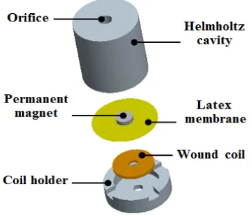
The acoustic energy harvesters reported in literature are based on piezoelectric transduction phenomenon. Up to author’s knowledge, no acoustic energy harvester is developed that is based on the principle of electromagnetism. The electromagnetic-based acoustic energy harvester reported in this work, consists of a Helmholtz cavity, flexible membrane, permanent magnets and a fixed wound coil. When the harvester is subjected to an acoustic wave, the Helmholtz cavity magnifies the amplitude of the acoustic wave and results in membrane (magnets) motion relative to wound coil. The coil experiences the changing magnetic flux and an elective motive force (emf) is induced in the coil. The lower output impedance of the developed electromagnetic based acoustic energy harvester provides an edge over the piezoelectric acoustic energy harvesters. In comparison, the output impedance of the piezoelectric based energy harvesters is very high, therefore low output current is expected, however, in electromagnetic-based acoustic energy harvesters high output current will be available to power the autonomous sensors.
II. ARCHITECTURE AND WORKING MECHANISM OF THE ENERGY HARVESTER
The cross-sectional view and exploded view of the developed AEH are shown in Fig. 1 and Fig. 2 respectively.
Figure 1. Cross-section of the developed acoustic energy harvester.
Figure 2. Exploded view of the developed acoustic energy harvester.
III. FABRICATION OF THE ENERGY HARVESTER
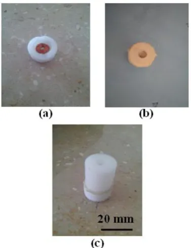
Figure 3. Photographic images of the energy harvester in various stages of the assembly: a) Coil placed in coil holder b) Suspension system fixed on coil holder c) Helmholtz cavity bounded on the
suspension system.
Fig. 3 shows the fabrication of the energy harvester device. Commercially available Teflon rod (WS Hampshire Inc. Hampshire, Illinois, USA) of 31.75 mm diameter is used to fabricate the Helmholtz cavity and coil holder. Conventional machining operations are performed on this rod to fabricate the Helmholtz cavity and coil holder. For membrane Natural Rubber Latex (Kleengaurd gloves, Kimberly Clark Co., Dallas, Taxis, USA) is used because of its high flexibility, better resistance to punctures and the tendency to self-repair tiny holes [23], [24]. To develop the oscillating structure for the energy harvester device, two NdFeB magnets are self-clamped on either side of the Latex membrane. Copper wire of 80 μm diameter is used to develop the wound coil. With the help of manual winding equipment a coil of 3 mm thickness, 12 mm diameter and 11845 turns is produced. The different parts of the device is assembled and fixed with the help of Epoxy. First, the coil is placed in the coil holder as shown in Fig. 3(a). To fix the coil in the coil holder epoxy is used. Two NdFeB magnets are mounted on the membrane. The magnetic polar attraction of the magnets is utilized to firmly attach the magnets to the oscillating membrane. Using epoxy the suspension system consisting of two magnets and the membrane is bounded to the coil holder as shown in Fig. 3(b). Finally, the Helmholtz cavity is placed on the suspension system and is fixed with sub-assembly with the help of epoxy Fig. 3(c). Table I lists the dimensions and parameters of the assembled energy harvester device.
TABLE I. DIMENSIONS AND PARAMETERS OF THE DEVELOPED
ACOUSTIC ENERGY HARVESTER
Description Value
Harvester dimensions 25 mm x 20 mm Magnet dimensions 1.60 mm x 6.35 mm
Magnet (NdFeB), Br 0.3 T
Mass of each magnet 377 mg
Membrane thickness 100 μm
Membrane diameter 13 mm
Coil dimensions 3 mm x 12 mm
Coil resistance 66 Ω
Number of turns of coil 11845
Gap between magnet and coil 2 mm
IV. EXPERIMENTAL SETUP AND HARVESTER
CHARACTERIZATION
The experimental setup for the characterization of the developed energy harvester for acoustic energy is shown in Fig. 4. The experiment setup consists of a power amplifier (Model A7-X, Kenwood, Japan), speaker, plane wave tube, function generator (Model GFG 8020H, GW Instek, New Taipei, Taiwan), microphone (Type CZ034A, Ringford products, Tsuen Wan, Hong Kong) and oscilloscope (Model GOS 6112, GW Instek, New Taipei, Taiwan). Function generator generates a sinusoidal signal of the desire frequency. Power amplifier amplifies this signal produced and gives it the speaker, which acts as an acoustic energy source. The acoustic energy produced by the speaker travels through the plane wave tube and impinges on the acoustic energy harvester. To measure the SPL of the incident acoustic wave, a microphone is fixed near the device. The signals from the energy harvester and microphone are analyzed using the oscilloscope.
Figure 4. Experimental setup for the characterization of the developed acoustic energy harvester.
that the behavior of the device is linear at low SPL, however, the harvester response is nonlinear at high SPL. The nonlinear response of the harvester is due to the nonlinear stiffness of the Latex membrane. The membrane stiffness is due to bending stresses and stretching. At low SPL the stretching is negligible and the membrane stiffness is only because of bending stresses that results in the linear stiffness of the membrane. However, at high SPL, stretching is considerable (and increases with increase in SPL) which induces excessive tensile stresses in the membrane that results in increasing the stiffness of the membrane [25], [26]. Under linear response, the harvester exhibits single resonant frequency (114 Hz) that shows the constant membrane stiffness in the linear regime of operation. However, at higher SPL the harvester response curve is tilted towards the higher frequency side. Moreover, the shift in the device resonant frequency, jump down (during increasing frequency sweep “IFS”) and jump up (during decreasing frequency sweep “DFS”) phenomena are also observed, which is due to the nonlinear stiffness of the membrane. Under nonlinear operation and subjected to 120 dB SPL, the harvester produced a maximum optimum load rms voltage of 315 mV at a resonance frequency of 144 Hz.
Figure 5. Optimum load voltage as a function of the frequency at various SPL.
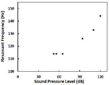
Figure 6. Resonance frequency shift with respect to increase in SPL.
The resonant frequency of the harvester during IFS, at low as well as high SPL’s is shown in Fig. 6. The shift in the resonant frequency of the harvester with the increase in incident SPL is associated to the nonlinear stiffness of membrane. Blow SPL of 56 dB is the linear regime of
operation for the device. The harvester, resonant frequency (114 Hz) remains constant in this region. Whereas, nonlinear regime of operation is above 56 dB SPL and in this regime the resonant frequency changes from 114 Hz to 144 Hz for a an increase of SPL from 56 dB to 120 dB.
Fig. 7 and Fig. 8 respectively show the voltage and powered delivered to load as a function of load resistance at different SPL’s. Various load resistances were connected to the harvester and it is excited at 65, 94 and 120 dB SPL’s at 114, 126 and 144 Hz resonant frequencies respectively. From Fig. 7 and Fig. 8, it is evident that greater the load resistance, higher is the voltage across it and smaller is the current through it. The maximum power delivered to load is 1503.4 μW at 120 dB SPL and at a resonance frequency of 144 Hz. The power delivered to the load is maximum at load resistance of 66 Ω, which is identical to the coil resistance, thus satisfying the maximum power transfer theorem [27].
Figure 7. Load voltage as a function of load resistance at different SPL’s.
Figure 8. Power delivered to load at different SPL.
Figure 9. Resonance frequency shift with respect to increase in load resistance at different SPL.
The experimental setup for characterization of the harvester in open air is shown in Fig. 10. Instead of a square channel for sound propagation, a relatively big speaker is used as an acoustic energy source. Acoustic energy harvester and a microphone are firmly placed adjacent to each other in a moveable wooden stand.
Figure 10. Experimental setup for the characterization of the developed harvester in open air.
Figure 11. Open circuit voltage produce by developed harvester as a function of the displacement from the acoustic source at various
directions and orientation
In order to verify the dependency of harvester on distance and orientation with respect to the acoustic source, the harvester is moved along three paths, perpendicular to the speaker, inclined at 45o and in-line with the speaker. Fig. 11 shows the rms value of the open circuit voltage as function of displacement from the speaker along the three lines. At 94 dB SPL and resonant frequency of 116 Hz, a maximum voltage of 230 mV is produced when the device is placed on the perpendicular line and at a distance 0.5 cm from the speaker. The voltage generation decrease drastically as the harvester is
moved away for the acoustic source. The voltage generation trends are similar when the harvester is moved along the perpendicular and 45o inclined lines. However, when the harvester is moved in-line with respect to the speaker, the generated voltage increases and reaches a maximum value of 78 mV at distance of 7.5 cm. Beyond a distance of 7.5 cm, voltage generation decreases with the motion away from the speaker.
Fig. 12 shows the experimental arrangement for the harvester characterization under the acoustical noise of a household electrical generator (5000 kW). National Instruments® (NI, Austin, Texas, U.S.) data acquisition card (NI USB-6212) and NI LabVIEW Sound and Vibration Assistant is used to obtained the signals simultaneously from the microphone and the acoustic energy harvester.
Figure 12. Experimental setup for harvester characterization under household electrical generator acoustical noise.
The output of the energy harvester when it is subjected to the acoustical noise of the household electrical generator is shown in Fig. 13. For this experiment the harvester is kept 30 cm away from the electrical generator. The SPL recorded at that distance ranges from 53 to 110 dB and is spread over a frequency range of 1 Hz to 2 kHz. The output response of the harvester is random, which was expected since the real acoustical noise is also chaotic and random. A maximum of about 30 mV load voltage is obtained when optimum load of 66 Ω is connected to the harvester.
Figure 13. Time response of harvester under household electrical generator acoustical noise.
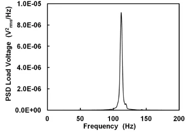
and Vibration Assistant the RMS averaging is used to generate the PSD plot shown in Fig. 14. The PSD of the load voltage is optimum at the resonant frequency of the harvester. A maximum PSD value of 9.17x10⁻⁶ V2/Hz is obtained at a frequency of 112 Hz.
Figure 14. Power spectral density of harvester output under household electrical generator acoustical noise.
The output voltage of the developed acoustic energy harvester is in mV range (20 to 315 mV), however, because of the low resistance of the wound coil (66 Ω) high output current levels would be available for powering the micro sensors. The power generation capability of the developed harvester is better than most of the reported acoustic energy harvesters and is quiet enough to power most of the ultra low power sensors.
A comparison of the developed harvester is done with the reported acoustic energy harvesters and is shown in Table II. The size of the developed AEH is quiet comparable to the harvesters reported in literature. The AEH mentioned in [17] and [20] are generating more power than the developed energy harvester, however, the output impedance of these harvesters is in higher range. The output impedance of the developed AEH is lower than all reported energy harvesters except [18] and [19]. While comparing on the basis of resonant frequency, the resonant frequency of AEH reported in this work is lower than all of the acoustic energy harvesters.
TABLE II. COMPARISON OF THE DEVELOPED ACOUSTIC ENERGY HARVESTERS
Type
Device dimensions (mm)
SPL (dB)
F (kHz)
R (Ω)
P
(μW) Ref.
Neck Cavity
Diameter Height Diameter Height
Piezoelectric 2.39 3.18 6.35 16.1 149 13.57 1000 6 x10⁻⁶ [8]
Piezoelectric 2.39 3.18 6.35 16.1 100 24 550 11x10-6 [14]
Piezoelectric - - - - 100 16.7 75 14x10-5 [15]
Piezoelectric - - 17.5 49 45 4.2 3900 40 x10-3 [16]
Piezoelectric 2.42 3.16 6.34 16.4 161 2.64 20000 30 x103 [17]
Piezoelectric - - - - 100 4.92 25 42.5x10⁻⁶ [18]
Piezoelectric - - - - 100 4.92 50 82.8x10⁻⁶ [19]
Piezoelectric 0.1 0.18 1.2 1.02 100 3.5 1000 1.69x10⁻³ [20]
Electrodynamic 2.5 4 6.5 16 125 0.143 66 1503.4 This
work
V. CONCLUSION
A miniature acoustic-based electrodynamic energy harvester is developed and reported in this work. The harvester is characterized in laboratory as well as in real life environment, such as household electrical generator surrounding. In laboratory the performance of the harvester is analysed under varying sound pressure level (SPL) and frequency. The harvester exhibited linear as well as nonlinear response. The response of the harvester is linear when subjected to low acoustic energy levels, however, at high acoustic energy levels it exhibited nonlinear behaviour. Under nonlinear operation it produced a maximum of 315 mV load voltage at SPL of 120 dB and 144 Hz frequency. When connected to the optimum load of 66 ohm, it delivered a maximum power of 1503.4 μW to the load. When the energy harvester is tested in the surrounding of a 8.8 kVA household electrical generator it produced a maximum load voltage of 30 mV and a maximum spectral power density of
9.17x10⁻⁶ V2/Hz under the acoustical noise level of 110 dB. The output power of the harvester is better than most of the other acoustic energy harvesters developed using piezoelectric material as a power producing element. The developed acoustic energy harvester is suitable to harvest energy for wireless micro sensors, for example, in turbofan engines, where the acoustic energy frequency band is from 20 to 20 kHz at about 150 dB SPL.
REFERENCES
[1] F. M. Gondal, “Embedded wireless sensor network for aircraft/automobile tire structural health monitoring,” M.S. thesis, Dept. Electrical and Computer Engineering, Virginia Polytechnic Institute and State University, Blacksburge, Virginia, April 2007. [2] H. Bai, M. Atiquzzam, and D. Lilja, “Wireless network for aircraft
health monitoring,” in Proc. 1st Annual conf. Broadband
Networks, USA, 2004.
[3] S. Roundy, P. K. Wright, and J. M. Rabaey, “Energy scavenging for wireless sensor networks with special focus on vibrations,”
[4] J. M. Gilbert and F. Balouchi, “Comparison of energy harvesting systems for wireless sensor networks,” International Journal of
Automation and Computing, vol. 05, no. 4, pp. 334–347, October
2008.
[5] F. Khan, F. Sassani, and B. Stoeber, “Copper foil-type vibration-based electromagnetic energy harvester,” Journal of
Micromechanics and Microengineering, vol. 20, no. 12,
November, 2010.
[6] T. Issarayangyun, D. Black, J. Black, and S. Samuels, “Aircraft noise and methods for the study of community health and well-being,” Journal of the Eastern Asia Society for Transportation
Studies, vol. 6, pp. 3293 - 3308, 2005.July.
[7] S. S. Jung, Y. T. Kim, Y. B. Lee, H. C. Kim, S. H. Shin, and C. Cheong, “Spectrum of infrasound and low frequency noise in passenger cars,” Journal of the Korean Physical Society, vol. 55, no. 6, pp. 2405-2410, December 2009.
[8] S. B. Horowitz, M. Sheplak, L. N. Cattafesta, and T. Nishida, “A MEMS acoustic energy harvester,” Journal of Micromechanics
and Microengineering, vol.16, no. 9, S174, 2006.
[9] R.Taylor, F. Liu, S. Horowitz, K. Ngo, T. Nishida, L. Cattafesta, and M. Sheplak, “Technology development for electromechanical acoustic liners,” Active 04 Paper A04-093, September 2004. [10] M. R. Mieszkowski, “Excessive vehicle noise impact and
remedies,” Digital Recordings co., Halifax, Nova Scotia, Canada, May 07, 2004.
[11] Y. Yokoyama and K. Hashimoto, “Development of low-noise air conditioning ducts,” JR East coTechnical Review., Japan, vol. 16, 2010.
[12] S. R. Anton and H. A. Sodano, “A review of power harvesting using piezoelectric materials,” Smart Material and Structure, 16 1-21, 2007.
[13] W. G. Cady, Piezoelectricity, Dover Publications, Inc.: New York, 1964, pp. 1-8.
[14] S. Shigeki, T. Tai, H. Itoh, T. Sugou, H. Ichioka, S. Kimura, and Y. Nishioka. “Lead zirconate titanate acoustic energy harvester proposed for micro electromechanical system/IC integrated systems,” Japanese Journal of Applied Physics, vol. 49, no. 4, 2010.
[15] S. Kimura, T. Shungo, S. Iizumi, K. Tsujimoto, T. Sugou, and Y. Nishioka. “Improved performances of acoustic energy harvester fabricated using sol/gel lead zirconate titanate thin film,” Japanese
Journal of Applied Physics, vol.50, no. 6, 2011.
[16] L. Y. Wu, L. W. Chen, and C. M. Liu, “Acoustic energy harvesting using resonant cavity of a sonic crystal,” Applied
Physics Letters, vol. 95, no. 1, July 2009.
[17] F. Liu, A. Phipps, S. Horowitz, K. Ngo, L. Cattafesta, T. Nishida, and M. Sheplak, “Acoustic energy harvesting using an electromechanical Helmholtz resonator,” Journal of the Acoustical
Society of America, vol. 123, no. 4, pp. 1983-1990, April 2008.
[18] S. Tomioka , S. Kimura, K. Tsujimoto, S. Iizumi, Y. Uchida, K. Tomii, T. Matsuda, and Y. Nishioka, “Lead zirconate titanate acoustic energy harvesters with dual top electrodes,” Japanese
Journal of Applied Physics ,vol.50, no. 9, 2011.
[19] S. Iizumi, S. Kimura, S. Tomioka, K. Tsujimoto, Y. Uchida, K. Tomii, T. Matsuda, and Y. Nishioka, “Lead zirconate titanate acoustic energy harvesters utilizing different polarizations on diaphragm,” Research Article Procedia Engineering, vol.25, pp. 187-190, 2011.
[20] A. B. Atrah and H. Salleh, “Simulation of acoustic energy harvester using helmholtz resonator with piezoelectric backplate,”
in Proc.2nd International Cong. Sound and Vibration, Bangkok,
Thailand, 7-11 July, 2013.
[21] M. Rossi, Acoustics and Electro Acoustics, Artech House, Norwood, MA, 1988, pp. 245- 308.
[22] D. T. Blackstock, Fundamentals of Physical Acoustics, John Wiley & Sons, Inc., New York, 2000, pp. 153-156.
[23] D. M. Korniewicz, “Intelligently selecting gloves,” Surgical
Services Management,” vol. 3, no. 2, 1997.
[24] M. Evangelisto, “Latex allergy: The downside of standard precautions,” Today’s Surgical Nurse, vol. 16, no. 5, September, 1997.
[25] J. S. Rao and K. Gupta, Theory and Practice of Mechanical
Vibration, New Age International Publication, 2001, New Delhi.
[26] F. Khan, F, Sassani, and B. Stoeber, “Vibration-based PDMS membrane type electromagnetic power generator for low vibration environments,” in Proc. Canadian Society for Mechanical
Engineering Forum, Victoria, Canada, 7-9 June, 2010.
[27] R. K. Wangsness, Electromagnetic Fields, 2nd ed., John Wiley & Sons, Inc., Hoboken, NJ. 587. 1986.
Dr. Farid U. Khan is born in Nowshera Pakistan in 1971. He completed his Bachelor’s and Master’s degrees in Mechanical Engin eerin g from Universit y of Engineering and Technology, Peshawar, Pakistan in 1997 and 2004 respectively. In 2011, from The University of British Columbia Vancouver, Canada, he did PhD in Mechanical Engineering. During the PhD studies his field of interest was Micro Electro Mechanical Systems (MEMS), vibration-based Electromagnetic energy harvester for MEMS devices, energy harvesting from sinusoidal and random vibrations. After completing B.Sc in Mechanical Engineering in 1997, he joined the department of Mechanical Engineering, University of Engineering and Technology Peshawar, Pakistan as a LECTURER. From 2002 to 2006 he worked as an ASSISTANT PROFESSOR in the same department. After completing PhD, currently he is working as an ASSISTANT Professor in the Institute of Mechatronics Engineering, University of Engineering and Technology Peshawar, Pakistan. His current field of interest comprise of Micro/Nano electromechanical systems (MEMS/NEMS), Low cost microfabrication technology, Microelectronics, Sensors and Actuators, Vibration-based energy harvesting, Electromagnetic energy harvesting, Random vibrations, Modeling of linear and nonlinear harvesters, embedded sensors, piezoelectric, electrostatic and acoustic devices. Micro-hydro turbines, Water Wheels, Pumps, power plants, refrigeration, biomedical devices, prosthetics and orthotics. Dr Farid is awarded Presidential Gold medal and University Gold medal for his distinction and extra-ordinary performance during his undergraduate studies. During his PhD studies in The University of British Columbia, Vancouver, Canada he also received JUST DISSERT AWARD 2009, UBC Alma Mater Society and GSS Appreciation Award 2011, Graduate Student Society UBC Vancouver for his role and contribution towards the betterment of Graduate Student Society UBC Vancouver.