Dynamic Network Function Chain Composition
for Mitigating Network Latency
Wajdi Hajji
∗, Thiago Lopes Genez
†, Fung Po Tso
∗, Lin Cui
‡, Iain Phillips
∗ ∗Department of Computer Science, Loughborough University, UK†Institute of Computer Science, University of Bern, Switzerland ‡Department of Computer Science, Jinan University, Guangzhou, China
Email: [email protected]; [email protected]; [email protected]; [email protected]; [email protected]
Abstract—Network Function Virtualisation (NFV) enables rapid deployment of new services in networks on an on-demand basis using general purpose servers. Multiple virtual network functions (VNFs) can be dynamically chained in an ordered sequence for the delivery of end-to-end services. Nevertheless, network latency caused by the sequential order of packet process-ing on every VNF can hurt the performance of latency-sensitive applications. To reduce such network latency, existing solutions only consider the maximum capacity of individual virtual net-work functions (VNFs) and do not take into account the fact
that performance of VNFs, as with any software applications,is
bottlenecked by either CPU or I/O peripheral capacity of the server they run on and their underneath implementation such as single-or multi-threaded.
By exploiting this knowledge, we can better determine the number of required VNF instances and distribute the network traffic among them for any given VNF chains. In this paper, we
formulate theVNF Scaling and Traffic Distributionproblem and
prove that it is NP-hard. We then present the design and
imple-mentation of Natif, an efficient VNF-Aware VNF insTantIation
and traFfic distribution scheme. Through our OpenStack-based
testbed evaluations, we demonstrate that Natif can significantly
improve the network latency by 188% on average as compared
to other approaches. As a chain composition scheme, Natif can
effectively work with any VNF chaining algorithms.
I. INTRODUCTION
Virtual Network Functions (VNFs) (e.g., firewalls, load bal-ancers) are often deployed in chains in between the communi-cating hosts [1]. Being in a chain, VNFs can provoke a mutual interference as they can change the volume of the processed traffic [2], which can cause resource, such as network and CPU, bottlenecks in the chain. As a result, network latency starts to build up and degrade the application performance, directly hurting revenue. It is reported that every 100ms of latency cost Amazon 1% in sales [3].
Current studies tackle the latency problem through VNF placement optimisation [4], VNF chaining [5][6] and VNF par-allelisation [7]. These methods improve latency by shortening end-to-end paths. However, they see VNFs as black boxes and neglect their internal packet processing characteristics. VNFs
Corresponding author: Dr. Fung Po Tso
This work has been partially supported in part by the UK Engineering and Physical Sciences Research Council (EPSRC) grants EP/P004407/2 and EP/P004024/1; the Chinese National Research Fund (NSFC) No. 61772235 and 61402200; the Fundamental Research Funds for the Central Universities (21617409).
are software applications running inside virtual environment. While software performance is bounded by either I/O or CPU or both of them, we argue that VNFs are no exceptions.
To demonstrate this, we have evaluated the resources usage at three VNFs, pfSense Network Address Translator (NAT), Snort Intrusion Detection System (IDS), and Suricata IDS. Each one of them is deployed on a Virtual Machine (VM) with 1Gbps vNIC, 1vCPU, and 1GB RAM. Fig. 1a depicts a clearly distinct CPU usage and CPU interrupts activities at pfSense NAT and Snort IDS in spite of being allocated similar resources and handling the same network traffic. This is because pfSense NAT is insensitive to the packet payload since it only handles the packet header. At each packet arrival it calls its subroutine running in the user space which results in high CPU interrupts (interrupt-driven I/O), hence I/O-bound. We have found that the effective computation of pfSense NAT is only around 2% of the total CPU usage. In comparison, the Snort IDS, using community rules1, buffers and inspects the data carried out in the packet payloads, a CPU-intensive task, hence CPU-bound. Interestingly, our experiments also revealed that Suricata IDS, a multi-threaded application, efficiently uses the CPU resources while Snort IDS, a single-threaded implementation, only uses one core at a time.
In this paper, we propose Natif2, a VNF-Aware VNF insTantIation and traFfic distribution scheme, as a way to reconcile the discrepancy of VNF requirements in the network chains. Natif considers the correlation between traffic and VNF category (CPU- vs. I/O-bound). For instance, when instantiating an I/O-bound VNF,Natif determines the required number of its instances based on the packet rate of the total incoming/entering flows (i.e., the throughput). Then, it implements a flow-based load balancer method that primarily considers the packet rate of each flow in the traffic distribution on the existing VNF instances. However, when dealing with CPU-bound VNF, both VNF instantiation and traffic distri-bution consider the bandwidth of the incoming flows (the amount of received data). Also, we argue that Natif can be seamlessly integrated into the VNF management approaches since it does not interfere with the VNF placement or chaining
1https://www.snort.org/downloads/#rule-downloads
0 20 40 60 80 100 120 5 10 15 20 25 30 35 >90% CPU
interrupts >90% CPU interrupts
<5% CPU interrupts <5% CPU interrupts C P U u sa ge ( %) Runtime (s) 20kpps x 1400 bytes / NAT
20kpps x 8 bytes / NAT 20kpps x 1400 bytes / IDS20kpps x 8 bytes / IDS
(a) CPU use at pfSense NAT and Snort IDS
0 20 40 60 80 100 120 0 10 20 30 40 50 60 70 C P U u sa ge ( % ) Runtime (s) Suricata/core(1)
Suricata/core(2) Snort/core(1)Snort/core(2)
(b) Multi-threaded Suricata IDS vs. single-threaded implementation in Snort
Fig. 1: VNF performance bottlenecks
but it complements them. In short, our contributions are four-fold:
• We experimentally demonstrate that an individual VNF’s
performance can be dependent on its host’s CPU and/or I/O capacity (CPU- or I/O-bound), and their underpinning implementation method (single- vs. multi-threaded).
• We mathematically formulate the VNF scaling and traffic distribution problem and prove that it is NP-hard.
• We propose and implementNatif for efficiently compose given VNF chain based on VNFs’ internal packet pro-cessing characteristics. We also open source our imple-mentation3 under the GNU General Public License.
• Our evaluation ofNatif with OpenStack show that it can significantly improve the network latency by 188% on average as compared with other methods.
The remainder of this paper is structured as follows: Section II mathematically models the problem. Section III describes the proposed solution. Section IV presents the system design and implementation of Natif. Section V describes the experi-mental setup and evaluation. Section VI states the related work and Section VII concludes the paper.
II. PROBLEMFORMULATION ANDMODELLING
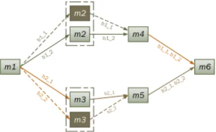
We consider a network that can be modelled as a directed graphG= (V, E)such as illustrated in Fig. 2, and we define the notations used in formulating the problem in Table I.
3https://github.com/SynNetSys/natif.git m1 m2 m3 m5 m4 m6 b1_2 m2 m3
Fig. 2: Initially, this network chain had two branches,b1 and
b2. After scaling outm2 andm3,b1 andb2 have been split into the sub-branches (b11,b12) and (b21,b22), respectively.
TABLE I: Notation
Symbol Description
M={m1, m2, . . .} List of VNFs
G= (V, E) Gdirected graph.V ⊂M.Elinks between elements ofV
CH={ch1, ch2, . . .} List of network chains
BRi List of branches ofchi∈CH
SBi List of sub-branches ofchi∈CH
F ={f1, f2, . . .} List of flows
P ={p1, p2, . . .} List of policies
mi.c,mi∈M Required CPU cores formi
mi.m Required memory formi
mi.cat 0 if mi is I/O-bound VNF, 1 if
CPU-bound
mi.cpps micapacity in packets per second
mi.cbps micapacity in bits per second
mi.gdf Gain/drop factor ofmi: ratio of
in-coming to outgoing traffic travers-ingmi
mi.gdpps Gain/drop factor in packets per
sec-ond
mi.gdbps Gain/drop factor in bits per second
mi.thd 0 ifmihas single-threaded
imple-mentation, 1 if multi-threaded
fi.src,fi.dst,fi.bps,fi.pps Source, destination, bandwidth,
and packet rate, respectively, of
fi∈F
pi.list,pi.len List of deployed VNFs bypi∈P
and its length, respectively.
The delay of flow when traversing a VNF is composed of a transmission delay and a processing delay. The former depends on the link capacity which is considered relatively stable in data centres [8]. The latter is due to the processing time, i.e. service time, of the incoming traffic plus the latency incurred by the packet queuing at the VNFs, i.e., the waiting time.
Let D be the transmission delay matrix, where
D(mi, mj) = D(mj, mi) is the delay between mi and
mj, andD(mi, mj) =−1if the delay is unknown ormi and
mj are not reachable. We define the service time as the time
that the VNF takes to process a packet or a bit of data based on its category. The service time of a VNF mi is given as
follows.
tis= 1/mi.cpps (1)
For simplicity, we consider M/D/1 queue at VNFs and VNFs process packets in a First-Come-First-Service (FCFS) discipline. We refer by λi to the arrival rate of all flows traversing mi. λi is determined by a Poisson process and is
λi= X
fi∈E(∗,mi)
fi.pps (2)
Given the utilisation ρi =λi×tis, the average waiting time
tiw ofmi is tiw= t i s×ρi 2(1−ρi) = λi×t i s 2 2(1−λi×tis) (3)
And the processing delay ofmi is:
tp(mi) = (
tis, λi≤mi.cpps
tiw+tis, otherwise (4)
The packet rate (throughput) and bandwidth of the egress flow at VNF mi are defined as follow.
fe.pps= mi.gdpps× X fi∈E(∗,mi) fi.pps, if λi≤mi.cpps mi.gdpps×mi.cpps, otherwise (5) fe.bps= mi.gdbps× X fi∈E(∗,mi) fi.bps, ifλi≤mi.cpps mi.gdbps×mi.cdps, otherwise (6) wherefi∈E(∗, mi)refers to all the flows enteringmi.
A. VNF scaling and traffic distribution optimisation problem The expected delay of a flow fi traversing a branch bi
governed by a policypi is construed as follows.
T(pi) =D(fi.src, pi.list[1])
+
pi.len−1
X
j=1
(D(pi.list[j], pi.list[j+ 1]) + tp(pi.list[j]))
+D(pi.list[pi.len], fi.dst)
(7)
Problem definition. Given the set of flows F, policies P,
VNFsM, chainsCH, their branchesBR, their sub-branches
SB, and delay matrix D. We aim to determine the needed number of instances of each VNF to ensure that all ingress flows are accommodated. Afterwards, we map the flows on the resultant chain sub-branches based on both flow and VNF properties to minimise the total end-to-end delay at the chains.
Minimise X pk∈P T(pk) Subject to: ∀pk∈P, pkis satisfied (C1) ∀pk∈P, ∀mi∈pk.list, X fi∈E(∗,mi) fi.pps≤ X mj∈Mi mj.cpps, mi.cat= 0 X fi∈E(∗,mi) fi.bps≤ X mj∈Mi mj.cdps, otherwise (C2) ∀fi∈E(∗, mi),∃mj∈ Mi, ( fi.pps≤mj.cpps, mi.cat= 0 fi.bps≤mj.cdps, otherwise (C3)
The constraints (C1) impose that all policies should be satisfied. (C2) ensure that there should be|Mi|VNFs capable
of handling all the incoming flows, either for I/O-bound or CPU-bound VNFs. (C3) highlight that in a flow-based distri-bution scheme, we might have individual flows that cannot be accommodated by any of the VNF instances. Hence, we ensure that for any flow traversing a group of VNF instances, there should be anmi that has the sufficient capacity.
The above problem can be proven to be NP-Hard.
Proof.Consider a special case that includes a chain of three
VNFs ofm1,m2, andm3 (in one branch) and is processing n flows. We suppose that initially m1 has not the sufficient
resources to handle the n flows but the other VNFs do. A reasonable solution is to scale out m1 by at least one unit.
In this new setup, the main branch will be split into two sub-branches. Then, the original problem becomes to find an appropriate sub-branch for each of the n flows that results in the overall low latency. Consider each flow to be an item, where its requirement (throughput and bandwidth) is the item size. Thus, each VNF can be seen as a knapsack kj with
limited capacitykj.cap. The profit of assigning flows to each
VNF is the negative of the flow delays. Then, our problem becomes finding a path for each flow through the VNFs that maximises the total profit. In other words, this becomes a Multiple Knapsack Problem (MKP) [9], whose decision version has already been proven to be NP-hard. Therefore, the MKP problem is reducible to our problem in polynomial time, and hence our problem is NP-hard.
III. VNF INSTANTIATING ANDTRAFFICDISTRIBUTION In this section, we briefly describe the three principles of our proposed solution.
A. VNF instantiation
We calculate the total packet rates and bandwidth of all flows traversing each branch of the chain. Then, depending on the VNF category (I/O- or CPU-bound), we determine how many instances needed for that VNF. We calculate the new flow attributes after traversing a VNF mi based on the
gain/drop factor. Afterwards, we run the VNF instantiation and we carefully allocate the number of cores to each instance (mi.c) by considering their internal implementation reflected
by the variable mi.thd (single- versus multi-threaded). In
particular case, if the VNF is single-threaded then the number of allocated cores will be the number of needed instances.
B. VNF-aware traffic distribution
In the flow mapping against the instances of a VNF mi,
we aim to reduce the likelihood of having no accommodated flows. Therefore, we start assigning the flows with the highest bandwidth ifmi is CPU-bound or the highest packet rate if it
is I/O-bound to the instances having the maximum remaining capacity (either in bits per second if mi is CPU-bound or
packet per second if mi is I/O-bound). Then, the flow status
Nova API Neutron API Ceilometer API
Nova Neutron Ceilometer
OpenStack Controller
Compute agent 2
Interactor
Tools to act on the cloud environment via OpenStack API (subroutines to create/delete server/port, stitch/update chain, etc.) Orchestrator
• Call the Interactor subroutines • Retrieve and
forward the traffic stats • Launch the Engine
modules
• Read and forward
the topology info
Engine
• Determine the
needed NF Instances
• Map flows onto
the chain branches • Predict flow
attributes for the next cycle.
...
Compute agent 1 ... Compute agent n
SFC Neutron La u nc h su br ou ti nes
Start Engine modules and receive feedback Feed Engine with topology
and traffic data
Traffic stats
Fig. 3: System design
updated, and we iterate the process with the other VNF in the chain. For a given VNF, the mapping finishes when there is no flow left untreated.
However, solely relying on the VNF category and the flow attributes can lead to poor mapping decisions. For instance, if at a CPU-bound VNF, we are receiving flows with negligible bandwidth, relatively to the VNF capacity in bits per second, but with high packet rate, considering only the bandwidth in the traffic distribution may create a congestion at one of the VNF instances. So we propose that if the flow bandwidth is negligible comparing to the capacity in bits per second of a CPU-bound VNF, then we consider the flow rate instead. Also, if the flow rate is negligible relatively to an I/O-bound VNF capacity in packets per second, we then consider the flow bandwidth in the traffic distribution.
C. Traffic characteristics prediction
Our proposal requires the identification of flow attributes over a period of time (e.g., a cycle). Therefore, we use the traffic statistics logged at the forwarding devices (OVS switch) to train a prediction algorithm to help in characterising the coming flows. For this purpose, we use the prediction model Arima [10] to determine the flows attributes. Without the output of the prediction or for bursty traffic, any new flow entering the network chain will be mapped to the set of the VNF instances in respect to the associated policy and based on its current attributes, i.e., at the arrival time.
Our controller makes decisions after each cycle of the traffic prediction run. The quality and reliability of working data, as well as their rate of change, determine the period of the cycle, which is in the order of minutes in our implementation.
IV. SYSTEMDESIGN ANDIMPLEMENTATION A. System architecture
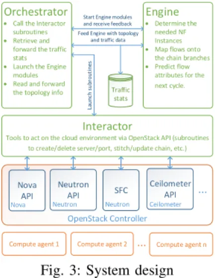
Natif is implemented in OpenStack4environment. Its mod-ules are deployed alongside the OpenStack controller. Our source code, around 1,500 lines, is written with OpenStack Python API. The controller has three main blocks. The Inter-actorprovides tools to instantiate VNFs, create network chains
4https://www.openstack.org/software/newton/
and perform traffic steering. The Engine implements Natif’s logic presented in section III. TheOrchestrator synchronises between the different modules as shown in Fig. 3.
B. Controller modules
• Chain reading and creation module reads the configura-tion files describing the chains details and then instanti-ates the VNFs on VMs.
• Flow mapping determines the path of each flow and calls the Service Function Chaining (SFC) subroutines to implement the forwarding rules.
• Chains update module updates the flow mapping by implementing/deleting the forwarding rules after each change on the chain topology.
• Flow attributes prediction module collects statistics on the traffic traversing the chain to train the Arima prediction model and then determines to flow attributes for the next cycle.
V. EXPERIMENTALEVALUATION A. Testbed experiment
We deploy OpenStack (one controller, two compute, and one storage nodes) on two servers with four 1Gbps NICs, 8 CPU cores and 32GB RAM each. The experiment involves chains of length three composed of NAT, firewall (FW) as representative of I/O-bound VNF and IDS for CPU-bound cat-egory. Measurements have been taken during five consecutive cycles of Arima prediction. We define three network traffic flavors/profiles. Profile 1 (P1): Six flows at high packet rate (20kpps) but low bandwidth (8-byte packet payload). Profile 2 (P2): Six flows with high bandwidth (1400-bytes payload) but random packet rates (normal distribution from 5kpps to 20kpps). Profile 3 (P3): mixed flows from P1 and P2. We also use two reference scenarios for the performance assessment. Greedy: it relies on the resources overprovisioning. It scales up all the VNFs by equally allocating all the available CPU cores and memory to them. Stratos-based5 (StratosB) [1]: It deter-mines the number of instances of each VNF and distributes traffic based on the total bandwidth of the ingress flows. Thus, StratosBensures a network-aware traffic distribution to reduce the likelihood of the network congestion and link saturation. For each scenario, we apply the three profiles, and then we measure the chain throughput (Mbps) and end-to-end delay.
B. Network metrics assessment
Fig. 4 shows howNatif has mitigated the RTT in the three profiles. Fig. 4a illustrates how, at the 90th percentile, Natif achieves 85% and 100% improvement compared to Greedy and StratosB, respectively. Fig. 4b shows the RTT for P2, StratosB outperforms Greedy, but it is still less efficient than Natif. When we apply P3 (Fig. 4c), Natif still outperforms StratosB as it has less RTT, 15ms compared to 30ms at 99th percentile inStratosB, which means an improvement of nearly 100%. It also achieves better results comparing to Greedy as
0.7 0.75 0.8 0.85 0.9 0.95 1 0 20 40 60 80 100 120 140 160 180 C D F RTT (ms) Greedy StratosB Natif
(a) Profile 1: high packet rate flows
0.7 0.75 0.8 0.85 0.9 0.95 1 0 20 40 60 80 100 120 140 160 180 200 C D F RTT (ms) Greedy StratosB Natif
(b) Profile 2: high throughput flows
0.9 0.91 0.92 0.93 0.94 0.95 0.96 0.97 0.98 0.99 1 0 20 40 60 80 100 120 140 160 180 200 220 C D F RTT (ms) Greedy StratosB Natif
(c) Profile 3: Mix of profiles 1 and 2 Fig. 4: RTT (ms) 0 0.1 0.2 0.3 0.4 0.5 0.6 0.7 0.8 0.9 1 0 0.0 2 0.04 0.06 0.08 0.1 0.12 0.14 0.16 0.18 C D F Throughput (Mbps) Greedy StratosB Natif (a) Profile 1 0 0.1 0.2 0.3 0.4 0.5 0.6 0.7 0.8 0.9 1 0 5 10 15 20 25 30 35 40 C D F Throughput (Mbps) Greedy StratosB Natif (b) Profile 2 0 0.1 0.2 0.3 0.4 0.5 0.6 0.7 0.8 0.9 1 0 5 10 15 20 25 C D F Throughput (Mbps) Greedy StratosB Natif (c) Profile 3 Fig. 5: Throughput (Mbps)
it decreases the latency to 10ms compared to 70ms at 90th percentile inGreedy.
In Fig. 4a, StratosB and Greedy do not capture that the high packet rate flows (even if it is incurring low bandwidth) can degrade the I/O-bound VNFs performance, like the FW and the NAT in the studied network chains. In Fig. 4b, we apply a high bandwidth traffic. StratosB properly recognises the needed VNF instances but it partially succeeds in making a correct traffic distribution since it does not consider the packet rate when dealing with flows traversing an I/O-bound VNF. For P3,StratosBstill performs well with high packet rate flows but not better than Natif since there is still high packet rate flows that need to be suitably distributed, thus, the results in Fig. 4b. Greedy focuses on the horizontal scaling of the VNFs, which does not help when the VNF has a single-threaded implementation so it will not be able to use all the allocated cores. Fig. 5a and 5b pick out a slightly identical behaviour of the throughput (Mbps) in the three approaches. However, Fig. 5c shows howNatif achieves 8% better throughput compared toGreedy andStratosB.
To conclude, Natif has mitigated the end-to-end delay without sacrificing the network throughput (Mbps), and in some cases, it improves both metrics simultaneously (P3). C. Traffic distribution and Arima model evaluation
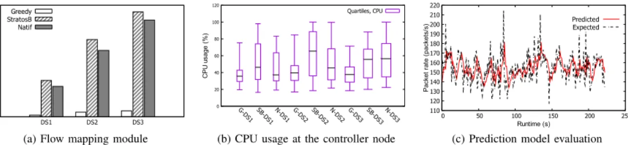
In this section, we measure the runtime of the traffic distribution module (also called flow mapping) of the three studied approaches, the CPU utilisation at the controller, and the prediction model efficiency. We define three data-sets that are the working data for the flow mapping. DS1: consisting of 100 VNFs, 30 chains, and 1k flows. DS2: 200 VNFs, 60 chains, and 2k flows. DS3: 300 VNFs, 90 chains, and 3k flows. In Fig. 6a, Natif outperforms StratosB, and Greedy has the shortest runtime. The runtime evolves linearly with larger data-sets, e.g., in Natif, it increases from 1s to 2.3s to 3.3s and in StratosB from 1.3s to 2.8s to 3.8s, for DS1, DS2, and
DS3, respectively. To explain this, we look back at how these approaches work. For example,Greedydistributes traffic on a static chain so it is taking the shortest runtime. When dealing with CPU-bound VNF, Natif and StratosB have almost a similarbehaviour. Whereas, when it comes to traffic traversing an I/O-bound VNF, StratosB still considers the bandwidth criterion while Natif primarilylooks at the packet rates and then the traffic bandwidth, in low priority. As a result, for the case of I/O-bound VNF, when considering the bandwidth rather than the packet rate, we can have more VNF instances since an I/O-bound VNF has less sensitivity to the bandwidth (e.g., NAT) than a CPU-bound VNF. Because spinning out more instances inStratosB, it is taking more time thanNatif. Fig. 6b shows the effect of the different algorithms on the CPU usage of the controller node. In DS1 and DS2, StratosB have the most significant CPU usage, then comes Natif, and lastly Greedy. As highlighted above, this reflects the logic behind each approach. However, in DS3,Natif slightly demands more computational resources than StratosB. Natif runs more iterations than the other approaches, and this may have a clearer repercussion especially with larger data-sets
Lastly, we have conducted a separate experiment consisting of predicting future traffic attributes (bandwidth and packet rate) based on past data of real traffic traversing a VNF (NAT). First, we trained Arima model with data of past 900 seconds (15 min) and then we measured the prediction accuracy. As shown in Fig. 6c, Arima model performs well in predicting the RTT of the ingress flows with an error of less than 30 packets per second.
VI. RELATEDWORK
VNF-VITAL [11] has presented a framework for VNF characterisation. The study has been based on Clearwater IMS VNF and two IDS VNFs (Snort and Suricata). It examines the horizontal and vertical scaling impact on the VNF performance regarding the CPU and memory utilisation. However, the
0 0.5 1 1.5 2 2.5 3 3.5 4 DS1 DS2 DS3 R un tim e (s) Greedy StratosB Natif
(a) Flow mapping module
0 20 40 60 80 100 120 G-DS1 SB-DS1N-DS1 G-DS2 SB-DS2N-DS2 G-DS3 SB-DS3N-DS3 C P U u sa ge ( % ) Quartiles, CPU
(b) CPU usage at the controller node
110 120 130 140 150 160 170 180 190 200 210 220 0 50 100 150 200 250 P acke t ra te ( pa cke ts/ s) Runtime (s) Predicted Expected
(c) Prediction model evaluation
Fig. 6: Evaluation of flow mapping module, controller node CPU usage, and prediction model. G, SB, and N refer to Greedy, StratosB, andNatif, respectively
study shows no consideration of the possible performance interference incurred by the VNFs since the evaluation did not cover performance of sequence of VNFs where chained, which we have achieved in this paper.
The authors in [2] have focused on an interesting aspect in the service chains. They have illustrated the traffic chang-ing effects of middleboxes and formulated the middleboxes placement problem to minimise the maximum link load ratio. Their proposed VNF chaining is relying on the gain/drop factor of each VNF but neglecting the fact that such chaining should fulfill well defined requirements such as the order of the VNF within the chain. Otherwise, this could probably lead to breaching the network policies that should have been correctly implemented by the chains. Our approach carefully considers the gain/drop factor without attempting any re-ordering that can violate policies.
Work presented in [12] has proposed a graph neural network-based algorithm that predicts future VNF components (VNFCs) resource requirements based on the collected CPU and RAM utilisation data. So, it would be possible to proac-tively allocate necessary resources to the VNFCs even before they could experience performance degradation. However, we believe that in some cases only considering the CPU or memory utilisation to understand the VNF performance would not be sufficient since the CPU usage metric can be misleading such as in the case of pfSense NAT. In our work, we have shown how the high CPU usage at pfSense NAT does not reflect the real computation need but it is a consequence of high CPU interrupts caused by the high rate of incoming packets (only 2% effective computation of the total CPU usage).
Other approaches such as [4][5][7] focus on the placement problem to minimise the end-to-end delay at the chains without considering the VNF performance. Instead, they model and manage the VNFs as identical entities.
VII. CONCLUSION ANDFUTUREWORK
NFV has facilitated the deployment and management of VNFs, but it has deepened the virtualisation overhead which particularly hurts the performance of latency-sensitive appli-cations. To compensate this overhead, we have proposed a simple but efficient solution that leverages the knowledge on VNFs to propose a VNF qualitative categorisation and chain composition proven useful in minimising the end-to-end delay.
However, apart from the simplified mathematical model, some issues remain unaddressed. Therefore, we aim in future work to answers to following questions. How to find out the gain/drop factor of certain VNFs such as Redundancy Eliminator since, in this case, the factor primarily depends on the packet payload (unlike NAT or proxy where the factor is known and static). Also, how we can tweak our approach to be applicable for bursty traffic where the Arima prediction algorithm would have insufficient time space to be trained.
REFERENCES
[1] A. Gember, R. Grandl, A. Anand, T. Benson, and A. Akella, “Stratos: Virtual middleboxes as first-class entities,”UW-Madison TR1771, p. 15, 2012.
[2] W. Ma, J. Beltran, Z. Pan, D. Pan, and N. Pissinou, “Sdn-based traffic aware placement of nfv middleboxes,”IEEE Transactions on Network and Service Management, vol. 14, no. 3, pp. 528–542, 2017. [3] J. Zhang, F. Ren, and C. Lin, “Survey on transport control in data center
networks,”IEEE Network, vol. 27, no. 4, pp. 22–26, 2013.
[4] A. Hirwe and K. Kataoka, “Lightchain: A lightweight optimisation of vnf placement for service chaining in nfv,” in 2016 IEEE NetSoft Conference and Workshops (NetSoft). IEEE, 2016, pp. 33–37. [5] S. Sahhaf, W. Tavernier, D. Colle, and M. Pickavet, “Network service
chaining with efficient network function mapping based on service decompositions,” in Network Softwarization (NetSoft), 2015 1st IEEE Conference on. IEEE, 2015, pp. 1–5.
[6] L. Cui, F. P. Tso, D. P. Pezaros, W. Jia, and W. Zhao, “Plan: Joint policy- and network-aware vm management for cloud data centers,”
IEEE Transactions on Parallel and Distributed Systems, vol. 28, no. 4, pp. 1163–1175, April 2017.
[7] Y. Zhang, B. Anwer, V. Gopalakrishnan, B. Han, J. Reich, A. Shaikh, and Z.-L. Zhang, “Parabox: Exploiting parallelism for virtual network functions in service chaining,” inProceedings of the Symposium on SDN Research. ACM, 2017, pp. 143–149.
[8] C. Guo, L. Yuan, D. Xiang, Y. Dang, R. Huang, D. Maltz, Z. Liu, V. Wang, B. Pang, H. Chen et al., “Pingmesh: A large-scale system for data center network latency measurement and analysis,” ACM SIGCOMM Computer Communication Review, vol. 45, no. 4, pp. 139– 152, 2015.
[9] H. Kellerer, U. Pferschy, and D. Pisinger, “Other knapsack problems,” inKnapsack Problems. Springer, 2004, pp. 389–424.
[10] H. Z. Moayedi and M. Masnadi-Shirazi, “Arima model for network traffic prediction and anomaly detection,” in Information Technology, 2008. ITSim 2008. International Symposium on, vol. 4. IEEE, 2008, pp. 1–6.
[11] L. Cao, P. Sharma, S. Fahmy, and V. Saxena, “Nfv-vital: A framework for characterizing the performance of virtual network functions,” in
Network Function Virtualization and Software Defined Network (NFV-SDN), 2015 IEEE Conference on. IEEE, 2015, pp. 93–99.
[12] R. Mijumbi, S. Hasija, S. Davy, A. Davy, B. Jennings, and R. Boutaba, “Topology-aware prediction of virtual network function resource re-quirements,”IEEE Transactions on Network and Service Management, vol. 14, no. 1, pp. 106–120, 2017.