TOMSK POLYTECHNIC UNIVERSITY
S.V. Efimov
COMPUTER-AIDED SYSTEM SOFTWARE
Recommended for publishing as a study aid by the Editorial Board of Tomsk Polytechnic University
Tomsk Polytechnic University Publishing House 2014
UDC 004.41(075.8) BBC 31.3я73
E91 Efimov S.V.
E91 Computer-aided system software: study aid / S.V. Efimov; Tomsk Polytechnic University. – Tomsk: TPU Publishing House, 2014. – 92 p.
The training manual provides basic information on automation systems, approaches to their developing and stages of designing software.
The training manual has been prepared on the basis of the original Russian language materials and it is fully consistent with the course of «Computer-aided system software».
UDC 004.41(075.8) BBC 31.3я73
Reviewers
Candidate of Physical and Mathematical Sciences Senior Research Associate
Institute of Monitoring of Climatic and Ecological Systems of the Siberian Office of the Russian Academy of Sciences
A.I. Gribenyukov
Doctor of Technical Sciences, Professor
The Head of Department of Automated Control Systems A.M. Korikov
© FSAEI HE TPU, 2014 © Efimov S.V., 2014
© Design. Tomsk Polytechnic University Publishing House, 2014
INTRODUCTION
The progress of technical, economic, social, and other spheres is hardly thinkable without automation of different processes at the present time. Automation of these processes is based on automation control systems which combine different sensors, tools, actuating mechanisms, microprocessor-based units, etc.
Automatic control system (ACS) is the firmware complex that provides automated collecting, processing, transfer and storage of data, which aimed at control optimization in different fields of human activity according to accepted standards. ACS are applied in different spheres nowadays: in power engineering, transport, industrial sector, etc. The term «automatic system» means the involvement of human resource in this system, i.e. a part of control function in either process is imposed on an individual.
Experience gained from the design and implementation of ACS makes it plain that the process control is based on set of rules, criteria, laws and requirements for this kind of control systems.
This book is devoted to automatic control system design, including ACS classification and types, standard requirements to ACS, ACS architecture, programmable logic controllers (PLC) designed to process automation, software for PLC and operator control stations.
1. ACS CLASSIFICATION
ACS are divided into two groups-information systems and control systems-according to general classification which is presented in modern bibliography devoted to automatic system control. The individuals, PLC, operator control station (OCS) play their own roles in these systems.
1.1. Information Systems
Information systems provide collecting, processing and output of measured information signals about technological or production progress in legible form: tables, mnemonic diagrams, graphs, trends, etc. Operator or control system determine what controlling actions are necessary at achieving optimal and favorable environment for the process behavior based on data received and related calculations. Data received can also serve as recommendations on process progress for operator. It is the individual who plays a key role for this type of systems. He makes decisions on process control based on knowledge provided by information ACS.
The primary task of these systems is accurate acquisition of production process performance information by operator. It enables the operator to make decisions for effective process control.
Information systems provide the process performance information and the information about situation caused by process parameter deviations.
Information systems are divided into passive and active systems. The passive system task is the information gathering for operator about process progress by operator request. The active information systems provide operator with data at given intervals or periodically and can include process control recommendations.
1.2. Control Systems
Control systems maintain the generation of control actions on executive mechanisms, or command executors, along with information acquisition and processing. The generation of control actions on executive mechanisms is performed in a real-time mode, i.e., at the same rate as the production process. Computing facilities perform the key role on control action generation in control systems.
2. ACS TYPES
According to purpose and application ACS can be divided into several types: automatic process control system (APCS), automatic control system of production (CAM), integrated automatic control system (IACS).
Each of the automatic control systems solves specific class of problems and has a set of functions and properties.
2.1. APCS
APCS is a system which provides acquisition and processing of information about technological process and generates control action on the control object according to given control parameters.
The tasks of APCS are operational status control of automation object, technological process control, etc.
APCS includes the firmware complex that provides technological process automation of any production as a whole or each production area taken separately.
APCS may include automatic control systems, and also microprocessor-based devices, which perform the local tasks of any object control. All these automation devices, including PLC, are combined in a complex system. APCS is a layered-structured system. Usually, the high-level operating system deals with information acquisition and storage about the technological process progress. There are different forms of information representation: trend, tables, graphs, mnemonic diagrams, etc. Operator can realize the remote control of technological process via the operating system interface. The system may have several OS depending on feasible APCS complexity and structure, e.g. performing such a task as backup and maintenance of APCS from the individual engineering station, etc. The industrial interfaces are used for the data connection of all local nodes and subsystems (PLC, OS, microprocessor-based devices, etc.).
The industrial implementation of APCS helps solve a number of problems and gain some advantages:
1) to provide manufacturing process safety using safety instrumented systems eliminating in this way human factors, un-cooperation of operators or their response time;
2) to cut the control system cost reducing the number of local devices, recording units and regulators (but this condition is not always satisfied);
3) to cut prime cost, boost productivity and improve production quality introducing a number of automated production procedures and optimization of equipment operation used in manufacturing process. 4) to implement the complex algorithms with a large amount
of manufacturing process parameters. It is only possible if a certain number of PLC tasks is accomplished.
2.2. CAM
Computer-aided manufacturing system is a system designed for solving control problems related to production and business activity of a company. The CAM objective is solving following problems of industrial management: business tasks (supply, sales, financial resources), personnel management is also of great importance in ACS (documentation, salary accounting, employment and dismissal procedures). The company document control is provided by means of CAM. Control actions are ensured by different documents – work instruction, orders, reports, etc. – and execution of these documents are realized by personnel in this system.
The possible tasks of CAM may include production planning adjusted for organization capacities, product analysis, production process modeling, product distribution and sales. Implementation of CAM leads to productivity improvement of organization.
2.3. IACS
Both APCS and CAM can run separately. However, organizations may combine them in one general system – IACS – to increase the production process efficiency. Coordinated control both of product or raw material technologies and industrial management within the entire organization is carried out by IACS. IACS application enables to organize the coordinated control of technological and production processes, and optimize enterprise activity as a whole. It should be noticed there are not so many organizations in Russia that can afford to explore these IACS- this will entail extensive business process reengineering and high financial expenditure. Organizations like Gazprom, Rosneft, Norilsky Nikel can afford the implementation of such systems.
3. ACS ARCHITECTURE
ACS architecture has layered structure. Field equipment is located at one level: detecting elements, sensors, actuating mechanisms. Cross equipment, control cabinets, including PLC are located at other level. OS used by operator for technological process control is at the third level. However, applying of particular control systems causes some of the finer points and complicated practical issues related to standardization, safety, commercial effectiveness, manufacturing equipment compatibility, etc. All these moments have eventually an impact on architecture of a designed ACS.
3.1. Architecture Requirements
ACS architecture is its abstract representation including idealized system components, and also interaction facilities between these components. Elements of architecture are interconnected and act as a one system, which provides problem solution of technological process automation at architecture level. Furthermore, architecture affords the opportunity to choose specific technological solutions due to project configured equipment, different data transfer interfaces, sensors and converters with different interfaces. So, properly designed system enables a variety of implementations by selecting architecture components and methods of their interaction.
Architecture elements are sensors, input-output devices, PLC, OS, interfaces, field bus networks, actuating mechanisms, drivers, etc.
The following characteristics should be provided by ACS architecture design: • loose coupling of architecture components;
• testability; • diagnosability; • maintainability; • reliability; • safety;
• easy service and operation; • security; • economical efficiency; • modifiability; • functional expandability; • extensibility; • openness.
3.2. Architecture Varieties
Different ACS structures are widely known at present: hierarchical, centralized, decentralized, etc. Each of them has its own advantages and disadvantages. A designed system structure is chosen depending on the tasks to be realized within manufacturing automation, technological algorithm complexity, system equipment.
Figures 1, 2, 3 present different layouts of ACS structure.
Figure 1. Centralized ACS Structure
A single central microprocessor-based device (SCC – supervisory computer complex) is used for acquisition and processing of information about all parameters and control instructions in centralized ACS structure.
The centralized structure is characterized by high control performance as SCC contains all the information about process status.
The disadvantage of this structure is low reliability because the SCC failure causes the failure of the entire system. It is possible to improve system reliability by SCC backup that leads to increase in the system cost.
Figure 2. Decentralized ACS Structure PLC
Sensors Actuating Mechanisms
Technological Process SCC
Sensors Actuating Mechanisms
Decentralized structure includes series of stand alone systems designed on the basis of separate PLCs. The control of PLC operation is performed by adjustment of initial setting or programs.
The advantage of the system with decentralized structure is high reliability (a PLC failure doesn’t cause failure of the entire system). A drawback of the structure is the lower quality of control compared to centralized structure, because there is no controller coordination in the process.
Figure 3. Hierarchical ACS Structure
An OS (operating system) is used for coordination of PC operation in hierarchical structure. Such a system provides high reliability and high quality of control. Most automatic control systems today are designed based on hierarchical structure.
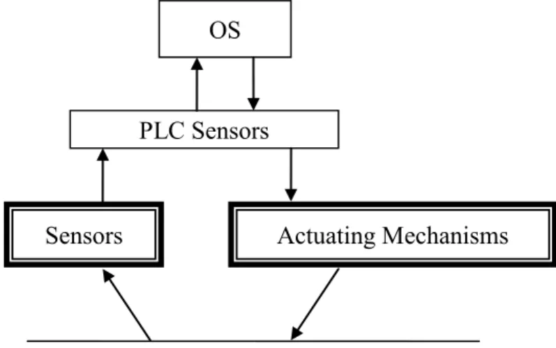
3.3. Information Flows
A large number of sensor elements different in design and operation principle are applied nowadays (detectors and sensors of temperature, pressure, level, rate, acceleration, frequency, humidity). Sensors generally convert physical quantities to unified electric signals. Then, the signal is transmitted to PLC input module, where analog-to-digital converter (AD converter) and microprocessor are built in. The microprocessor allows to linearize sensor response, compensate errors, apply data filters. Input module is directly connected to PLC. It was previously mentioned that PLC are configured according to project, it means that all the components – microprocessor, interface, input-output modules are selected relying on system parameters, complexity of technological algorithms and tasks.
PLC Sensors
Sensors Actuating Mechanisms
Technological Process OS
There are various input-output modules, which differ in number of processing signals, type of actions (analog, discrete, impulse-number actions, etc.) Also, analog input-output modules are divided into current-controlled (4–20 мА, 0–20 мА, 0–5 мА), voltage (0–10 В, 0–5 В, 0–100 мВ, etc.),
thermal resistance converters (platinum, copper converters, etc.), thermocouples (chromel-alumel, chromel-copel, etc.)
In addition to analog input modules, discrete input modules are widely used. These modules don’t comprise ADC and handle signals that have two levels (limit switches, level detectors, pressure, temperature sensors, door sensors, etc.). Impulse-number input modules have discrete input and calculate an amount of impulses or impulse frequency. These modules are applied, for instance, by shaft motor speed measurements.
To realize technological algorithms an OS is designed that supports PLC operations by means of software tools allowing PLC programming according to required algorithms. To connect PLC with OS the industrial networks Ethernet, Controlnet, RS-485, Profibus, etc. are explored.
The software – SCADA system – is installed in OS to design ACS graphic interface. The graphic interface describes technological process (mnemonic schemes, graphs, trends, process diagrams, etc.) and automation and remote control tools on operator control station (key buttons, control boards, controllers, etc.).
The SCADA and PLC communication is provided in a variety of ways. But the most common way is using of OPC server.
Information about programming PLC, SCADA, OPS servers and their communication is considered in the following sections.
Control signals sending from OS (from SCADA ACS) to PLC, and also control signals automatically generated from PLC (according to specified standards and technological algorithms) arrive at output modules.
Output modules can generate different signals: discrete, frequency, analog. Output module generally contains an embedded digital-to-analog converter (DA converter) in case it’s needed. Converted signals enter the control systems of technological equipment: valves, pumps, motors, gates, etc.
There is a visible tendency to the distinction elimination between PLC and computer. The PLC introduction was authorized by the high cost of computers at the time. More and more industrial computers are used nowadays, which have special configuration, designed for round-the-clock
4. ACS Functions
ACS function is a list of system activities aimed at a local control purpose. The following functions are distinguished:
• data – computing functions; • control functions.
Supplying the information to operator station about the process progress is the result of executing data-computing functions.
A purpose of control functions is providing the control actions on automation object.
Data – computing functions include:
1) acquisition, processing and storage of information; primary information processing includes input signal filtering, rating the information reliability, analytical calibration of sensor, i.e. accessing the status information by data received from the sensor; 2) signaling the equipment and technological conditions;
3) indirect measurement of process and equipment parameters;
4) calculating the engineering and economical performance characteristics of manufacturing process;
5) recording of required parameters, equipment condition and results of estimations provided by the system or PLC;
6) recording of process and equipment deviations;
7) analyzing and detecting the initial cause of occurred lockouts and technological protections;
8) forecasting the parameters of manufacturing process and equipment;
9) diagnostics of ACS equipment;
10) displaying the progress information and providing guidelines for technological process control;
11) performance of information exchange with other ACSs. Control functions include different control types:
1) single-loop control (control by certain parameters of technological process);
2) logic control (lockouts and protection); 3) cascade control;
4) multivariable control; 5) program control;
6) optimal control of steady-state process (optimal control in static mode);
7) optimal control of unsteady process (optimal control in dynamics), solution of this problem is the law of parameter variation from one static mode to another one;
8) optimal control of manufacturing process with adapting the control system.
5. BASIC FUNCTIONS OF PLC AND OCS
Basic functions of PLC:1) acquisition and primary processing of information; 2) parameter control;
3) program control; 4) warning;
5) safety protection; 6) fault diagnosis;
7) data transmission to the operator control station; 8) command receipt and execution.
The controller programming is performed by means of special systems. Basic functions of OCS:
1) displaying of information in form of mnemonic schemes, graphs (trends), numerical values, tables, text messages, animation, etc; 2) information backup;
3) report generation;
4) variation of control parameters; 5) manual remote control.
6. ACS STRUCTURE
ACS includes technical, mathematical, information, and organizational support.
Technical support includes microprocessor controllers, PC-based operator control stations, data collection and data transmission devices, execution units, etc.
Mathematical support divided into algorithmic support and software.
Algorithmic support is a combination of interrelated algorithms for ACS operating.
Software is a set of programs designed for control of operator stations and microprocessor controllers.
Organizational support represents documentation required for ACS maintenance: engineering manual, maintenance manual for operating staff, repair manual, etc.
Information support is a list of documents which contain information about set of input signals, their characteristics, set of output signals including presentation model of output information, and schemes of information acquisition, processing and using
The diagram of the certain support types interaction is presented in figure 4.
Technical Support
Organizational
Support Operating Staff
Input
Information Information Support Information Output
Computer Aids
Mathematical Support: • algorithmic • software
7. IEC-61131 STANDARD
Industrial automation systems are rapidly developed in recent decades. PLC hold one of the central positions in ACS. Increasing in PLC production demands unification of programming tools which provides programming of PLC operation. To achieve this goal, the IEC – 1131 standard was designed later renamed as IEC 61131.
7.1. Standard Evolution
Development of PLC standards was initiated in 1979 when an ad hoc group was created with the participation of technical experts. In 1982 the first version of the standard was issued. However, it was decided to divide the standard into five directions to overcome difficulties in working with this paper.
Five divisions were organized to design the standard in the following directions:
1) background information;
2) equipment and testing requirements ; 3) programming languages;
4) user manuals; 5) message design.
Later the fifth direction was divided into two ones: • message specification design;
• programmable controllers – communication.
The section «Programming Languages» is of particular interest as a part of the considered book. At first the standard was published under the name IEC 1131-3 in 1993, but in 1997 IEC changed the standard notifications by adding «6», so the standard was converted into IEC 61131-3
7.2. The IEC 61131-3 Characteristics
Programming systems based on IEC-61131-3 incorporates following characteristics:
• reliability of designed software. The reliability is maintained by the fact that the PLC programs are designed by means of dedicated development environment, which includes all necessary tools for program writing, testing and debugging using emulators and real PLCs as well as the number of completed code chunks;
• ability to easy program modification and program functionality increase;
• project portability from one PLC to another one; • ability to reuse of completed program segment;
• programming language simplicity and limitation of language elements.
7.3. Standard Languages
IEC-61131-3 provides PLC programming languages. Software is designed in such a way that certain parts of code can be developed in different standard languages, and then integrated to single executable software.
Structured programming, encapsulation, abstract types, etc were included into IEC-61131-3.
The implementation of IEC-61131-3 languages was based on analysis of various languages, which were already used. IEC-61131-3 defines five programming languages.
IEC-61131-3 includes graphic languages: Ladder Diagrams (LD) and Function Block Diagrams (FBD). These languages provide correspondence between graphics primitives describing solution of a particular problem and programs, which implement problem-solving algorithms. A certain primitive performs a particular task by setting input parameters.
The element base of LD includes a set of symbols for string programming. Ladder diagram programs are relay circuits including normally closed and normally open contacts, relay windings.
The element base of FBC looks like function blocks interconnected to electric circuit. This form of graphic representation makes the language easy to work with a lot of applications with inter-component data transfer. Function blocks, which form the language basis, are program objects that execute particular control and calculation algorithms. Output data of this block can be transmitted to other blocks by trace lines.
In addition to considered programming languages, IEC-61131-3 includes also Sequential Function Chart language (SFC). The element base of SFC is formed by steps and junctions which can be applied in algorithms described in any other standard languages.
a high level language used for structured programming. ST provides the work with arithmetic and Boolean operations and includes following programming structures: environment, cycles, multiple selection operator, etc.
7.4. Requirements to Standard’s Languages
IEC-61131-3 languages are based on following principles:
• the program is divided into a number of functional elements – Program Organization Units (POU). Each unit may consist of functions, functional blocks and programs; each unit can be hierarchically configured from simpler elements;
• IEC-61131-3 demands strong data typing, data type specification helps to detect most bugs before the program execution;
• there are tools to execute different program parts at different times, at different rates, and simultaneously;
• Sequential Function Charts (SFC) are used for certain operation sequence set by time intervals or events;
• IEC-61131-3 supports structure to define heterogeneous data, e.g. pump bearing temperature, pressure and on/off state can be defined by an integrated structure and then transferred as a single data unit within the program;
• the standard provides sharing of five languages, so the best suited language is chosen for each part of task;
• a program written for one type of controllers can be transferred to another type compatible with IEC-61131-3;
• any PLC operates in repetitive mode; a cycle starts from data collection from input modules followed by PLC program execution. Data output from output module completes the cycle, so the runtime of the cycle depends on input-output duration and processor module speed.
7.5. Standard’s Relevancy
There is no doubt that the implementation of IEC-61131-3 had its impact on users and PLC designers alike.
The standard language tools for PLC programming provides personnel training in this industry sector. Availability of the fixed language list enables the training of experts who are capable to program industrial PLCs from different manufacturers due to the fact that the basic software meets IEC-61131-3. On the one hand, engineers and system integrators should
study five languages for PLC programming, on the other hand, this training technique is standardized.
Usually, PLC manufacturers design both hardware and software, and deliver the PLC programming software in set with controller. Some companies such as Siemens, Emerson, Rockwell Automation also deliver software for SCADA OS design as well as software for SCADA and PLC communication. However, there are PLC manufacturers that use canned software for PLC programming. Wago and OVEN companies, which use in their controllers software from 3S Softaware Ltd., are good examples of such enterprises. It should be pointed out that there are differences in SW element base, in syntax, etc. by different manufacturers despite the fact that the software is developed according to IEC-61131-3. However, all these differences are not serious and studied within a short time.
The next advantage of IEC-61131-3 implementation is a possibility to build integrated control systems, which include controllers from different manufacturers.
7.6. Development Trends of Standard
Issues of IEC-61131-3 development are discussed in different conferences, seminars, webinars and other events all over the world. However, the large majority of programming system manufacturers still concentrate all their efforts just on service development avoiding significant improvements in language development.
Programming is tool – limited in most cases. Although many of modern controller platforms support C#, a compiler provides just the aspects of programming. Function of system debugging and launching are nearly unsuitable for controller applications. E.g., the library calls should be written to monitor input – output values.
Based on the above stated, tendency to IEC – 61131-3 extension is to be noticed. This extension should meet following standard’s requirements:
• OOP of this extension should not be optional, not compulsory; • interoperability of OOP with not object oriented programming; • application support with possible transformation as required to OOP; • OOP implementation to all IEC – 61131-3 languages.
This standard extension is already developed by 3S-Smart Software Solutions. The main IEC – 61131-3 extension concerns the function block
transformation to a class. In the same way the C# structures were transformed into classes. This is achieved by method introduction. In fact, method is a function built in a function block. So, not only function parameters and local variables, but also instance data of function block are available by function implementation. As a result, method call includes both instance and method names.
The power increase due to OOP implementation enables interface creating. An interface is understood to be a set of methods using common parameters, but different realization ways for different function blocks. An interface can be transferred as a parameter, and the software component doesn’t actually bother what function block should be applied.
8. TOOLS OF PLC DESIGN
Currently, PCs are used for PLC programming. Software design, testing and debugging processes are developed by special-purpose software systems. PLC manufacturers generally use their own programming tools for software development. These programming tools are already adapted to certain equipment. It is obvious that PLC manufacturers are not interested in versatile software production since they have incentives to promote just their own products in the market.
The IEC – 61131-3 openness and complexity of programming tool system implementation lead to establishing of specialized companies developing PLC programming tools.
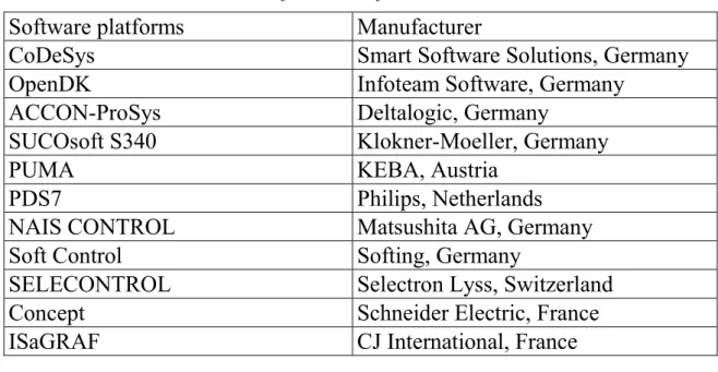
A list of these programming tool systems based on IEC – 61131-3 includes more than twenty products. The most common software platforms are listed in the table 1.
Table 1
Software Platform List Software platforms Manufacturer
CoDeSys Smart Software Solutions, Germany
OpenDK Infoteam Software, Germany
ACCON-ProSys Deltalogic, Germany
SUCOsoft S340 Klokner-Moeller, Germany
PUMA KEBA, Austria
PDS7 Philips, Netherlands
NAIS CONTROL Matsushita AG, Germany
Soft Control Softing, Germany
SELECONTROL Selectron Lyss, Switzerland
Concept Schneider Electric, France
ISaGRAF CJ International, France
The IEC – 61131-3 as additional components is supported lately in some SCADA systems (FIX/Paradym-31, Factory Suite/InControl, WinCC/WinAC, TraceMode , etc.).
The IEC – 61131-3 language programming will be considered through the example of CoDeSys designed by 3S – Smart Software Solutions (http://www.3s-software.com). CoDeSys is one of the most functional IEC –
8.1. PLC Programming System Tools
One of the main tasks of PLC programming environment is automation of software developer work flow. It helps reduce time of software development and deliver a developer from monotonous routines.
Today each of the companies are intend on increasing a number of service functions leading to more rapid and comfortable software development. Service functions have not been included into IEC – 61131-3 requirement list, but selection of development environment depends on its usability.
8.1.1. Embedded Editor
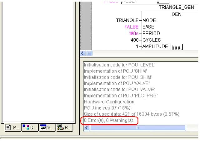
Compiler is usually called as embedded editor. A compiler task is to read programs written on IEC – 61131-3 languages and convert text or graphic code into machine code. A result of compiler operations is a final version of software which executed afterwards. A development environment supposes that embedded editor is provided. In case of software bugs compiler points out program ID, its line number and error type, otherwise, it points out absence of errors as illustrated in Fig. 5.
8.1.2. Text Editor
IEC – 61131-3 supports five programming languages, CoDeSys development systems includes six programming languages; the graphic language CFC is also on the list. There are text languages – IL and LD – on this list. Implementation of text languages in development system demands a number of certain characteristics:
• fast entry of text elements, keyboard combinations which provide insertion of orders, functions, functional blocks and other standard elements;
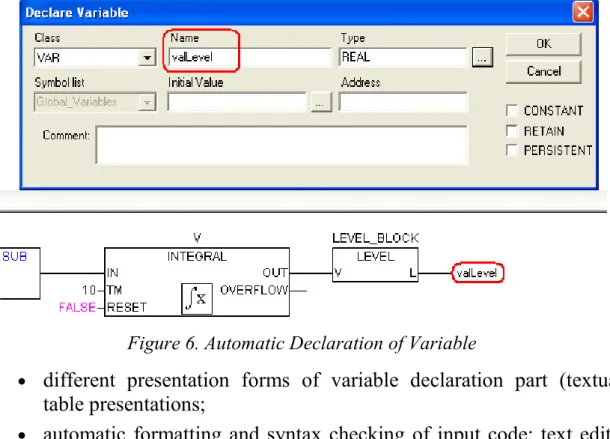
• automatic completion of input data, e.g., variables could be declared in short form in declaration part, but they are converted into required form upon completion;
• automatic declaration of variables; if a new identifier is used in program code, the declaration window pops up where a variable class, type, initial value, etc, can be defined. The window Declare Variable pops up by creation of output variable with the name valLevel (Fig. 6);
Figure 6. Automatic Declaration of Variable
• different presentation forms of variable declaration part (textual, table presentations;
• automatic formatting and syntax checking of input code: text editor highlights reserve words, commands, comments, etc. by different colors;
8.1.3. Graphic Editor
Similarly, there is a graphic editor for IEC – 61131-3 graphic languages. This editor has a number of characteristics aimed at speeding and developer environment improvement:
• automatic routing of block connecting lines;
• automatic component layout, it is true for LD, FBD and SFC programs, for CFC CoDeSys developer defines component layout by himself prioritizing the component execution;
• automatic numbering of algorithm chains;
• copying, insertion and transferring of program graphic elements; • zooming of graphic code on display for its better presentation or
detailed view;
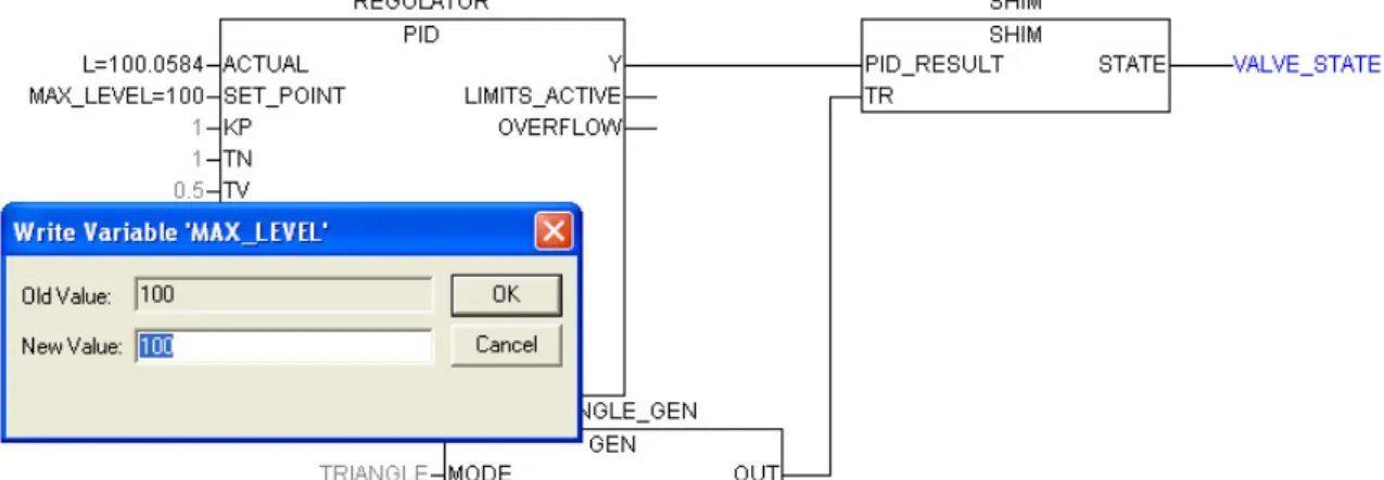
• active circuits and variables are highlighted online in different line weight and colors; in fig. 7 displays the variable VALVE_STATE highlighted by blue color, so this points to its True value;
• the input values are displayed in program blocks online which can be overwritten (if the input parameter is defined by a variable); Fig. 7 illustrates that the input values are displayed in PID controller block, double clicking on MAX_LEVEL variable called a pop-up window for overwriting its value.
Figure 7. Writing of Variable MAX_LEVEL New Value
8.2. Project Debugging
Software environment designed for PLCs includes the following functions of debugging:
• mechanism of connection to PLC or PLC emulator; the type and the way of connection make no difference, and can influence just any particular physical characteristics mostly related to physical implementation;
• providing the designed code loading of the control program into PLC RAM; automatic monitoring of loaded code; comparing the loaded code gained after the compilation with the code which is already contained in PLC memory [CoDeSys informs that no software is available on the controller in case of initial SW loading (Fig. 8), otherwise, that the loaded software has been changed in comparison with the PLC code version (Fig. 9)];
Figure 8. SW Loading into PLC • control program operates in real-time mode;
• the execution of the control program code is stopped under spare fault condition, but other process stages are kept working (it is possible to monitor manually the parameter values at inputs and
outputs а PLC);
Figure 9. SW Reload in PLC
• flush of data, which are stored in PLC, different types of data flush are possible: «hot» flush, «cold» flush, and factory flush (by the «hot» flush the control program is returned to initial state, and the variables take the initial values; by the «cold» flush the transition of the control program to initial state and initial value setting of the variables are also supplemented by initial value setting of the variables, which are located in volatile memory; and the factory flush provides for deleting the user control programs and restoring memory and controller settings aligned by manufacturer);
• input, altering, and monitoring of variable instantaneous values in project;
• control program stepping (line by line, by one running cycle) with allowed breakpoints;
• keeping track of variable cross-references in control programs.
8.3. Project Management Tools
The source environment of bundled software designed for PLC programming includes project management tools. Problems of project management are solved by means of project manager, which enables:
• presenting the components and the structure of the designed project; • working with project components (create, rename, relocate, copy,
delete);
• setting of project resources;
• controlling the project libraries (connecting the available libraries and adding any private libraries);
• preparing the project documentary including: ♦ textual representation;
♦ description of project components and section of variable declarations
♦ resources of designed project – PLC configuration, list and description of global variables, list of project problems, list of the libraries available;
♦ cross – references list of the project variables.
8.4. Project Recovery
The need for source code updating arises anyway in operating of the introduced automatic control system. However, the potential source file loss of the introduced project should never be ruled out. This problem can be solved differently. The storage of all source codes in PLC memory is most common. Files are usually compressed, archived and stored on memory card. Another approach to solving the task is the code decompiling, conversion of the executable code to IEC programs. This approach, however, is more complicated by realization, so it is uncommon.
8.5. Security
The access to altering and modification of the source code is usually secured with the help of ACS administrator keyword. Limited access raises security level of ACS and eliminates the write access for outsiders.
9. STRUCTURE BY PLC
Source environment for creating the PLC code has a clear structure. The project tree or project structure is displayed in project manager. The example of a project structure is presented in Figure 10.
Figure 10. Project Tree
This structure includes a program named PLC_PRG and LEVEL, SHIM, VALVE function blocks. The POU type is shown in brackets: a program, a function block, a function. However, there are more global elements in source environment such as tasks, source, configuration, which are considered in this section.
9.1. Tasks
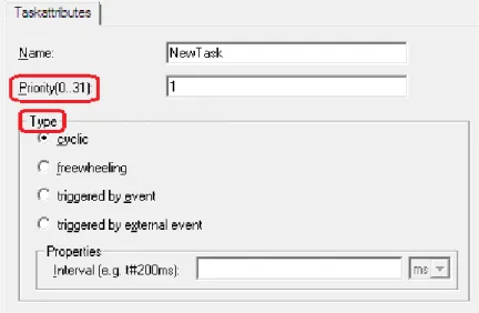
The key task appointment is operation control of project programs which are performed by PLC processor. Each task has its unique identifier (program name). A separate task can control not only one, but a number of programs performed within every operating cycle of PLC. It is possible to create several tasks both of similar and also of different types within one project. There are tasks of different types, e.g.. cyclic, independent (freewheeling), triggered by event (see Fig. 11). Triggered by event tasks are performed by an event defined by rising edge variable, which conforms to this event. Cyclic tasks are performed at the time intervals which are set by project designer. Freewheeling tasks are also performed in a cyclic way, however, there are not fixed time lags between task performances in freewheeling tasks, so they proceed to n+1 performance upon completion of the n-iteration.
Task description are performed through a variety of native means (text or graphics) in different source environments. In CoDeSys the Resources tab contains the task configuration folder where tasks are set and task attributes are defined (see Fig. 12).
Figure 11. Task Attributes
To perform the PLC programs at least one task should be set in any project. In CoDeSys there is one cyclic task on default, wherein the PLC_PRG program is included.
Tasks are controlled by the executive. Tasks should be prioritized to control the performance process. Task priority is defined by the assigned number in the range of 0-31 (see Fig. 11). The lower the number the higher the priority of the task performed. If several tasks to be performed, the task of higher priority is performed first. If there are two tasks with the same priority to perform, the task with longer waiting time is performed first. If two cyclic tasks of different priorities are delivered synchronized, the task with lower priority is not performed at all.
The nonpreemptive multitasking are generally realized in the PLC software executive. I.e., if the task of higher priority than the currently performed task appears in the waiting list, no performance interrupt will take place. The currently performed task will be executed till the end of the cycle.
Figure 13. Project Resources The resources tab includes the following list of items:
• global variables and direct addressable variables; • library manager;
• target settings of the executive: microprocessor type, memory allocation, network parameters, and other settings;
• task configuration.
To simplify the work with source environment different PLC software manufacturers also include their original tools into resources such as network configuration, instruction control unit for PLC core, logs, etc.
9.3. Configuration
In relation to resource one more entity of a higher level is concerned in IEC. This is configuration. Configuration integrates a variety of resources working by a certain law. One system can include a number of resources each of which contains a processor, memory, a runtime system. Such resources can be both real modules, which are widely separated, and virtual ones, which are emulated by one process. All these modules have an access to certain hardware (PLC input-output modules), and their work and interconnection are synchronized by project global variables.
The configuration definition is generally used in distributed ACS to solve more challenging specific tasks.
10. PROGRAM ORGANISATION UNITS
10.1. POU Definition
Program organization units are basic elements, which are used in project code creating. Each POU has an individual interface, name and description in one of the IEC 61131-3 languages.
The POU definition was touched upon in section 9 and it was defined that function blocks, function and programs are related to the basis program organization units.
POUs are basic components for building the entire project code. Each unit has its individual identifier (its name), specific interface, and described in one of the IEC 61131 languages.
The POU call can be realized in different ways. Unit «program» is called to the executing by a specified task, and also by another POU, executing program. Units such as functions and function blocks are called to executing only by programs. The key feature of PLC software is recursion unfeasibility, because it is forbidden by IEC 61131.
The encapsulation characteristic is widely applied in PLC software, i.e., POUs are created on the «black box» principle: all details are hidden from users, and the information about inputs, outputs and current task of the POU suffices to work. It is unessential to have the information about POU internal arrangements. In graphic languages POU is represented as a rectangle with inputs at the left, outputs at the right, and with the name at the top (see Fig. 14). Local data are not available externally.
Figure 14. Type of Component in FBD Language
Applying the encapsulation characteristics in the project helps solve the problem of structural decomposition. Project is built from a bigger unit to a smaller one. A designer aligns the target settings in resources, sets the type of processor, configures PLC, sets up tasks, connects the required libraries, defines the set of global variables, etc. Then, in tasks created, designer calls
blocks. Thus, a certain group of tasks is solved at each design level of the project without going into details. To turn to details the unit of lower rank should be considered.
The next accompanying problem is solved by realizing the structural decomposition. This problem is the localization of variable identifiers. I.e., designing the certain blocks it is possible to use repeated names of variables for local variables, because the scope of variable names is the unit where they are used. It allows to simplify the project structure effectively, and reduce the global variable declaration list.
10.2. Formal and Current Parameters
The POU interface is provided by its name and its input and output variables as well. The POU input parameters are usual to name as formal parameters. The external variables of certain values are connected to the input variables (formal parameters) by using the POU. These parameters are called current parameters. Thus, by POU activation, its parameters gain current values entering the unit, and processed according to the algorithm realized within this unit, and after that the output values are recorded into current parameters.
10.3. POU Parameters and Variables
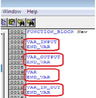
The variable declaration contains variables of several types: VAR_INPUT, VAR_OUTPUT, VAR, VAR_IN_OUT (see Fig. 15).
Current values enter to the formal input parameters VAR_INPUT by copying. The parameter types should be coincided. A current parameter (an external value of the unit) enters the unit in each operating cycle of PLC. The formal output parameters VAR_OUTPUT are formed out of the unit operating. Similarly, data are recorded into current parameters by copying. The variables from VAR section are local and can be used just within this unit.
The VAR_IN_OUT variables can be inputs and outputs simultaneously. The variable values to the unit are passed by reference. I.e., the external variable outside the unit operates as an internal variable within this POU. By creating a POU with the variable from the VAR_IN_OUT section only the variable address is passed to the POU. There are series of restrictions for the variables from VAR_IN_OUT section:
• banned from use in functions;
• giving the starting values is off-limits; • not used as element of data structure;
• variable assignment is possible only by block calls.
10.4. Functions
Function is a program organization unit, which includes a variety of input values at the output. Function always returns only one value (which can consist of a number of elements in case of bit-mapped field or structure). The function name is a sort of output variables, where the calculating results are recorded. The type of returned value, the function name, and input parameters are provided in function declaration.
The function unit is realized without the internal memory available. Function may contain local variables, however, they are uploaded from memory when process is finished. The lack of memory means that function always returns the same value by similar values of input parameters.
The type of returned value is any one from the list of value types provided be environment and also from the user created types. Function body can be described in any of IEC languages except for SFC language, because there is no proper syntax in this language. It can just define the structure and the order of code priority. Calling other library and user functions is possible to realize in function body, but the call of function blocks and programs is impossible to perform therein.
10.5. Function Blocks
Function block is a program organization unit that can take, process and return arbitrary number of values. A function block unit is called in program code. In contrast with functions, function blocks can’t generate the returned values. All variable values are stored after the execution of a function block instance till the next call. Since the function blocks have internal memory and can store the variable values the called instances with similar input data can have different output data.
The external reference to the function block makes available just its inputs and outputs. The access to the function block instance variables is unavailable.
10.6. Programs
Program is a global POU which is able to generate don’t care values during the calculations. All variable values are stored after the program execution finished and stored till the next program call. In contrast with function blocks, programs have no instances, they are global POUs of entire project and set at the resource level of the project.
11. THE IEC 61131 LANGUAGES
Five PLC programming languages are included in IEC – 61131 as was mentioned earlier: IL, LD, FBD, ST and SFC. In addition to the mentioned above, one more language is incorporated in CoDeSys languages. This is CFC, a redesigned graphic language, where the execution priority of algorithmic blocks is set by their mutual arrangement. The IEC programming languages are considered next in the section.
11.1. The IL (Instruction List) Language
The IL language is an instruction list. This is a typical assembler with accumulator and label transitions. Set of instruction is standardized and doesn’t depend on a certain target platform.
Each instruction is written in a separate line. An instruction can include 4 fields separated by spaces and tabulation characters:
Label: Operator Operand Comments
The instruction label is not obligatory, it is used if required. Operator is an obligatory field. Operand is nearly always to be presented. Comment is not obligatory field, written at the end of the line. It’s forbidden to insert comments between instruction fields.
Text alignment is automatically performed by editor in addition to syntax checking and highlighting.
11.1.1. Result Register
Absolute majority of IL instructions perform an operation with the content of the result register. The IL result register is a general-purpose container able to save the variable values of any type.
Translator doesn’t report an error when the value of type BOOL, and then of type INT or REAL is put into result register. This flexibility doesn’t mean that the result register can contain several values of different types. It can be just one, moreover, the value type is registered in the result register. If operation demands another value type, translator will give an error message.
11.1.2. Jump to Label
The IL language program is executed top-down. To change the order of execution and loop organization the jump to label is applied. A jump to a label can be unconditional – JMP- performed regardless of anything. A conditional jump JMPC is performed only if the result register value is TRUE. A jump is performed running up and down. Labels are local, i.e., a jump to another POU label is not allowed. E.g.:
LD 1 (*load a value into result register *)
ST Counter (*set the current result value to variable *) loop1: LD Counter (*load Counter into result register *) ADD 1 (*add 1 to result register *)
ST Counter (*set the result register value to Counter *) LE 5 (*result register value less than or equal <= 5*) JMPC loop1 (*jump to label*)
11.1.3. Parentheses
The execution order of IL instructions is possible to change by means of brackets. Left parenthesis is put in instruction after operation. Right parenthesis is put in a separate line. Instructions within parentheses are performed first. The result of calculating the instructions given in brackets is registered in additional result register, and then the program, which contains a left parenthesis, is executed. E.g.:
LD 5 MUL (2 SUB 1 ) ST y (*y=5*(2-1)=5*) LD 5 MUL 2 SUB 1 ST y (*y=5*2-1=9*)
Parentheses can be nested. Each nesting demands any temporary result register. This causes ambiguity by exiting the parentheses with instructions JMP, RET, CAL, and LD. It is prohibited to use these instructions in parenthesis.
11.1.4. Modifiers
The instruction content is modified by adding the C and N modifiers to the mnemonics of some operators.
The «N» modifier (negation) initiates a reverse operand value before the instruction performed. The operand types should be BOOL, BYTE, WORD, or DWORD.
The «С» modifier (condition) provides the condition evaluating of JMPC, CALC, RETC: these instructions are only performed if the result of preceding expression is TRUE. N with JMPC, CALC, RETC: the instruction is only then performed if the result of the preceding expression is FALSE. N without C makes no sense in these instructions.
11.1.5. Operators
The standard operators of IL languages are summarized in the table (see table 2).
Table 2
The IL Operators
Operator Modifier Meaning
LD N Make current result equal to the operand
ST N Save current result at the position of the operand S If the current result is TRUE, put the Boolean operand at TRUE R If the current result is TRUE, put the Boolean operand at FALSE
AND N, ( Bitwise AND
OR N, ( Bitwise OR
XOR N, ( Bitwise exclusive OR
NOT Bitwise result inversion
ADD ( Addition
SUB ( Subtraction
MUL ( Multiplication
DIV ( Division
End of table 2 GE ( >= QE ( = NE ( < > LE ( <= LT ( < JMP CN Jump to label
CAL CN Function block call
RET CN Exit from POU and return into calling program
11.1.6. Calling Function Blocks and Programs
Calling a function block or program in IL is possible with simultaneous variable assignment. E.g.:
CAL CTD_1(CD:=TRUE, LOAD:=FALSE, PV:=10) LD CTD_1.CV
ST y
A similar call with preliminary variable assignment: LD TRUE ST CTD_1.CD LD FALSE ST CTD_1.LOAD LD 10 ST CTD_1.PV CAL CTD_1 LD CTD_1.CV ST y 11.1.7. Function Call
There is a significant feature by calling a function with parameter enumeration in IL. The result register is used as the first parameter:
LD TRUE SEL 3,4
11.1.8. Annotation
11.2. Structured Text (ST)
The ST language (Structured Text) is a high level language and resembles Pascal because it is based on it. Instead of Pascal procedures the program components of IEC 61131-3 are used in ST.
11.2.1. Expressions
Expressions provide the basis for a ST-program. The expression evaluation result is assigned to a variable with the operator «:=» as in Pascal. Each expression ends in «;» (simicolon)
ST operators are represented in symbolic expressions, e.g., mathematical operations +, –, *, /, comparison operations, etc .
Several expressions can be written in one line. Long expressions can be taken down to the next line. The line brake is equal to the passive distributor.
An expression can include another parenthesized expression. The parenthesized expression is calculated first
11.2.2. Order of Expression Evaluation
The expression evaluation is performed according to the rule of operator precedence. Operations of the highest priority are performed first.
In order of descending, operations are ranged in the following sequence: parenthesized expression; function call; EXPT degree; character replacement (–); negation NOT; multiplication, division, and division modulo MOD; addition and subtraction(+, –); comparison operations (<, >, <=, >=); equality(=); inequality(<>); logical operations AND, XOR and OR.
11.2.3. Empty Clause
An empty clause consists of a semicolon «;». Translator doesn’t generate any code for the semicolon. If an excessive semicolon is put occasionally, it will be a semicolon of language construct. E.g., a project should be translated which contains an unrealized POU. For the concise translation one empty clause should be written in POU body.
11.2.4. Selection Statement IF
Selection statement enables to perform different expressions depending on conditions of logical statements. The full syntax of the operator IF looks like this:
IF <Boolean statement IF> THEN <statements IF> ; [
ELSIF <Boolean statement ELSEIF 1> THEN
<of statement ELSEIF 1>; …
ELSIF <Boolean statement ELSEIF n> v THEN
<of statement ELSEIF n>; ELSE
<of statement ELSE>; ]
END_IF
The part of code within the brackets [ ] is not obligatory.
11.2.5. Multiple Selector CASE
Multiple selector CASE enables to perform different statement groups depending on the value of one integer or one statement. Syntax:
CASE <integer> OF
<value 1>: <of statement 1>; <value 2>: <of statement 2>; <value 3> : <of statement 3> ; … [ ELSE < of statement ELSE> ; ] END CASE
11.2.6. While and Repeat Loops
WHILE and REPEAT loops provide the statement iteration while the Boolean conditional statement is true. If the conditional statement is always true, the loop becomes infinite.
The WHILE syntax:
WHILE < Boolean conditional statement> DO <Statements – loop body>
Condition in the WHILE loop is proved before the loop starts. If the Boolean statement initially has the FALSE value, the loop cycle will be performed not even once.
Syntax REPEAT: REPEAT
<statement – loop body >
UNTIL < Boolean conditional statement > END_REPEAT
Condition in the REPEAT loop is proved after the loop body has been performed. If the logic statement initially has the FALSE value, the loop cycle will be performed just once.
A well-formed WHILE or REPEAT loop should definitely alter the variables, which make the terminating condition in the loop body, progressing towards the terminating condition. Otherwise, the loop will never end.
11.2.7. FOR Loop
The FOR loop provides the given number of statement block iterations. Syntax:
FOR <int counter> := <Starting value> ТО <Ending value> [BY <Step>] DO
<statements – loop body> END_FOR
Counter receives the starting value before the loop starts. The loop body is repeated as long as the counter value exceeds the ending value. The counter get increased in each loop. Starting and ending values and step can be both constants and statements.
11.2.8. Iteration Interrupting by EXIT and RETURN
The EXIT operator, put in iteration body WHILE, REPEAT and FOR, results in immediate loop terminating.
For internal loop EXIT terminates only «its own» loop, the external loop will continue working.
The RETURN operator realizes the immediate return from POU. This is the only way to interrupt the nested iterations without additional condition evaluating.
11.3. Ladder Diagrams
The ladder diagram language is a graphic language which realizes the electrical circuit structures.
Graphically, a ladder diagram is presented as two vertical power supply rails with the circuits in-between formed by contact connection. A relay is used for the circuit load. There are contacts to be applied in other circuits in each relay.
Boolean series connection (AND), and parallel contact connection (OR), and inverse (NOT) form the Boolean basis. As a result, LD is absolutely appropriate not only for on-off controllers but also for implementing the combinational logical networks. The implementation area of LD language is almost unrestricted due to the fact that function and function blocks written in other languages can be included into LD
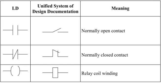
Key elements are presented below, in the table 3.
Table 3
The Basic Elements of LD language
LD Design Documentation Unified System of Meaning
Normally open contact
Normally closed contact Relay coil winding
11.3.1. Latching Relay
Besides traditional relays the polarized relays are often applied in relay circuits. The relay of this type has two opposing coils switching the relay over two states. This is achieved by current impulses. When the current is switched off, the relay remains in its last state, and this realizes a low-level memory cell.
Latching relay is realized in LD by means of two coils SET and RESET. The coil of SET type is marked by parenthesized letter (S). The RESET coil are marked by letter (R), also in parentheses. If a variable, which corresponds to the (S) coil, takes the TRUE value, it keeps this value infinitely. To return the variable to the FALSE value is possible only by means of the (R) coil.
11.3.2. Execution Order and Feedback
The relay circuit method requires the parallel running of all circuits. The current is supplied simultaneously to all circuits.
The diagram solution in LD is performed top-down from left to right. All diagram circuits are one-shot performed in each cycle. This creates the effect of parallel circuit running. Any variable within one circuit always possesses the same value. Even if the relay alters the variable value, the new value will be transmitted to contacts only in the next cycle. Circuits of a lower level receive the new variable value immediately. Circuits of a higher level receive the new value just in the next cycle.
The diagram execution order can be changed in a forced way by means of labels and jumps.
A label can be set only at the circuit beginning. Label names should conform to the variable name instructions. It is possible to finish the label by a colon. The colon doesn’t generate a new label. Thus, M1: and M1 amount to the same thing. A circuit can contain just one label and one jump. The jump is equivalent to output relay and performed if the output variable has the TRUE value. If the jump is inversed, it will be performed by the FALSE value of the variable. A jump enables to ignore the execution of a diagram part. The ignored circuits are not removed, but just ignored – they are remained at the same state as before the jump. The upward jump is available and allows the cycle creation. Testing the conditions of the cycle termination is a task of a programmer.
Ideologically, jumps contradict the LD analogy with relay circuits, because they violate the electric circuit laws. But jumps are happen to be taken.
11.3.3. LD Enhancement
Functions and function blocks can be inserted into LD diagram. Each function block should have logic input and output.
To include functions in a diagram the extra Boolean input EN (Enable) is imposed into these functions. The Boolean value at the input EN enables
or disables the function performance. There are no internal changes of the function by adding the EN input.
11.4. Function Block Diagrams
Function Block Diagram (FBD) is a graphic programming language. A function block diagram is built from POUs, which are displayed as rectangles in the diagram. The POU inputs are displayed left from the rectangle, and output areon the right side of the rectangle. The POU type and names of inputs and outputs are represented within the rectangle. For the function block its name is displayed above the rectangle. In graphic programming systems the POU rectangle may contain the image which displays the POU type. The size of the rectangle depends on the number of inputs and outputs and set automatically by the graphic editor.
11.4.1. Bussing
The POU в FBD rectangles are connected by communication lines. Bussing is directed from left to right. The POU input can be connected to the output of the POU leftward. Moreover, the input is connected to a variable or a constant. Bussing should connect variables or inputs and outputs of the same type. As opposed to a POU, a variable is displayed without a rectangular frame in the diagram.
11.4.2. FBD Execution Order
The FDB circuits are executed top-down from left to right. The function blocks located left –of – other blocks are executed first. A function block is calculated only after calculating the values of all block inputs. The further calculation is performed after all output values have been calculated. In other words, all the output values are presented simultaneously. The circuit calculating is considered to be finished after the output value calculation of each POU.
In some programming environments a user can relocate the function blocks avoiding failure of connections. The FBD order in the program is to be considered in this case.
11.4.3. Boolean Signal Inversion
The Boolean signal inversion is displayed in FBD as a circle before the input or a variable. Inversion is not a characteristic of the function block, so it can be added or cancelled immediately within the diagram.
11.4.4. Connectors and Feedback
Connectors are the labeled connections, which can be broken and transferred to the next circuit. This method is reasonable by the limited window width of FBD editor.
The standard doesn’t prohibit connectors linking the block output to its own input or the input of the block which precedes it in the network. Feed back doesn’t form a loop similar to FOR, just any evaluated value will be used at the input by the next diagram call. In practice, this means the implicit creating the variable that keeps its value between the diagram calls.
The inverse connectors are prohibited in CoDeSys FBD editor. To create the inverse connection the explicitly declared internal variables are used. If the connection transfer or fanout to another circuit are necessary, the intermediate local variables are used.
11.4.5. Labels, Jumps and Return
The order of execution of FBD circuits can be changed imperatively using labels and jumps exactly as in relay circuits.
A label is set at the beginning of any circuit and is per se the name of this circuit. A circuit can have just one label. The label names conform the common IEC rules for identifier names. The graphic editor numbers diagram circuits. This numeration is used for documentation only and can not replace the labels.
A jump is connected with the Boolean variable and performed if the variable has the TRUE value. The constant TRUE is used to realize the unconditional jump.
The RETURN operator is used in FBD as well as the jump to the label, i.e., connected with the Boolean variable. RETURN leads to immediate completion of POU and the return to high-level nesting. This is the start of the PLC running cycle for the main program.
11.5. Sequential Function Charts
Sequential Function Chart diagrams are ranked above the other four languages in IEC. The SFC diagrams are high-level graphic tools.
11.5.1. Steps
Each SFC is built from the units, which provide step and jump conditions. Steps in SFC programs are displayed as rectangles. The actual work of a step is described in a certain dialog and isn’t displayed in the diagram. The purpose of the SFC step is represented by its name and, if it is not sufficient, by a concise text description (a comment).
Steps can be empty, and it doesn’t cause errors by project compiling. The empty steps are considered to be a standard in top-down programming, which is common to SFC. It is possible to identify the action corresponding to the step at any time.
11.5.2. Transitions
There is a horizontal line below the step on the connector line. This line displays a transition.
A Boolean variable, a Boolean statement, a constant, or a direct address can be used as conditions for a transition.
A transition is performed if both of the following conditions are met:
1) transitions is enabled (the step corresponding to this transition is active);
2) its condition has the TRUE value.
Simple conditions are displayed at the diagram right from the line, which describes the transition.
The approach to complicated conditions is quite different. The transition identifier is written in the diagram instead of condition. The condition is written in the diagram directly in a separate dialog window using IL, ST, LD, or FBD languages.
Variables or direct addresses are used in a condition only for reading. The POU call or assignment operations are impermissible in a conditional statement.
The fact, that the transition identifier is an individually realized condition, and not a simple Boolean variable, is indicated in the diagram by means of a small triangle in the upper corner of the ractangle.
A Boolean constant can be established as a condition for the transition. If the constant value is TRUE, the step will be performed just once within one running cycle. Then, the control is transferred to the subsequent step. If the constant value is FALSE, the step will be performed infinitely.
11.5.3. Initial Step
Each SFC begins with the step which box frame is graphically marked with a vertical double line or with a double line along the perimeter. This is the initial step. The initial step name is automatically generated (Init by default). The initial step is the obligatory element of SFC, although, it can be empty.
11.5.4. Parallel Branch
A sequential function chart can diverge, that is the processing line can be branched into two or several further lines («branches»). Parallel branches will be processed parallel (both at a time). Parallel branches within a chart are preceded by a horizontal double line (see Fig. 16). A parallel branch must begin and end with a step. I.e., the entry condition is common to all parallel branches, so as the output condition.
Figure 16. Parallel Branches
Theoretically, the parallel branches are executed simultaneously. Practically, they are executed in one running cycle from left to right.
The subsequent transition, which ends the parallel branches, is evaluated only if the last steps of all parallel branches are active.
Figure16: Step 2 will be processed just once. Steps 1 and 3 will be processed parallel to one another before the subsequent transition 4will be noticed.
11.5.6. Alternative Branch
Some of the SFC lines are alternative. The horizontal lines before and after the branched area are simple lines (see Fig. 17). An alternative branch must
beginning line is active, then the first transition of each alternative branch will be evaluated from left to right. The first transition from the left, whose transition condition has the TRUE value, will be opened and the following steps will be activated.
Figure 17. Alternative Branches
In this case, the а alternative is evaluated first. Steps 2 and 3 can be activated only if the а value is FALSE.