® ®
Process Control and Automation Solutions from Elsag Bailey Group
E96-434
Analog Input Termination Module
(NIAI02)
WARNING notices as used in this instruction apply to hazards or unsafe practices that could result in
personal injury or death.
CAUTION notices apply to hazards or unsafe practices that could result in property damage.
NOTES highlight procedures and contain information that assists the operator in understanding the
information contained in this instruction.
WARNING INSTRUCTION MANUALS
DO NOT INSTALL, MAINTAIN, OR OPERATE THIS EQUIPMENT WITHOUT READING, UNDERSTANDING, AND FOLLOWING THE PROPER Elsag Bailey INSTRUCTIONS AND MANUALS; OTHERWISE, INJURY OR DAMAGE MAY RESULT.
RADIO FREQUENCY INTERFERENCE
MOST ELECTRONIC EQUIPMENT IS INFLUENCED BY RADIO FREQUENCY INTERFERENCE (RFI). CAU-TION SHOULD BE EXERCISED WITH REGARD TO THE USE OF PORTABLE COMMUNICACAU-TIONS EQUIP-MENT IN THE AREA AROUND SUCH EQUIPEQUIP-MENT. PRUDENT PRACTICE DICTATES THAT SIGNS SHOULD BE POSTED IN THE VICINITY OF THE EQUIPMENT CAUTIONING AGAINST THE USE OF POR-TABLE COMMUNICATIONS EQUIPMENT.
POSSIBLE PROCESS UPSETS
MAINTENANCE MUST BE PERFORMED ONLY BY QUALIFIED PERSONNEL AND ONLY AFTER SECURING EQUIPMENT CONTROLLED BY THIS PRODUCT. ADJUSTING OR REMOVING THIS PRODUCT WHILE IT IS IN THE SYSTEM MAY UPSET THE PROCESS BEING CONTROLLED. SOME PROCESS UPSETS MAY CAUSE INJURY OR DAMAGE.
AVERTISSEMENT MANUELS D’OPÉRATION
NE PAS METTRE EN PLACE, RÉPARER OU FAIRE FONCTIONNER L’ÉQUIPEMENT SANS AVOIR LU, COMPRIS ET SUIVI LES INSTRUCTIONS RÉGLEMENTAIRES DE Elsag Bailey. TOUTE NÉGLIGENCE À CET ÉGARD POURRAIT ÊTRE UNE CAUSE D’ACCIDENT OU DE DÉFAILLANCE DU MATÉRIEL.
PERTURBATIONS PAR FRÉQUENCE RADIO
LA PLUPART DES ÉQUIPEMENTS ÉLECTRONIQUES SONT SENSIBLES AUX PERTURBATIONS PAR FRÉQUENCE RADIO. DES PRÉCAUTIONS DEVRONT ÊTRE PRISES LORS DE L’UTILISATION DU MATÉ-RIEL DE COMMUNICATION PORTATIF. LA PRUDENCE EXIGE QUE LES PRÉCAUTIONS À PRENDRE DANS CE CAS SOIENT SIGNALÉES AUX ENDROITS VOULUS DANS VOTRE USINE.
PERTURBATIONS DU PROCÉDÉ
L’ENTRETIEN DOIT ÊTRE ASSURÉ PAR UNE PERSONNE QUALIFIÉE EN CONSIDÉRANT L’ASPECT SÉCURITAIRE DES ÉQUIPEMENTS CONTRÔLÉS PAR CE PRODUIT. L’AJUSTEMENT ET/OU L’EXTRAC-TION DE CE PRODUIT PEUT OCCASIONNER DES À-COUPS AU PROCÉDÉ CONTRÔLE LORSQU’IL EST INSÉRÉ DANS UNE SYSTÈME ACTIF. CES À-COUPS PEUVENT ÉGALEMENT OCCASIONNER DES BLESSURES OU DES DOMMAGES MATÉREILS.
NOTICE
The information contained in this document is subject to change without notice.
Elsag Bailey, its affiliates, employees, and agents, and the authors and contributors to this publication specif-ically disclaim all liabilities and warranties, express and implied (including warranties of merchantability and fitness for a particular purpose), for the accuracy, currency, completeness, and/or reliability of the information contained herein and/or for the fitness for any particular use and/or for the performance of any material and/ or equipment selected in whole or part with the user of/or in reliance upon information contained herein. Selection of materials and/or equipment is at the sole risk of the user of this publication.
This document contains proprietary information of Elsag Bailey, Elsag Bailey Process Automation, and is issued in strict confidence. Its use, or reproduction for use, for the reverse engineering, development or manufacture of hardware or software described herein is prohibited. No part of this document may be photocopied or reproduced without the prior written consent of Elsag Bailey.
Preface
Termination modules provide an input connection from the plant equipment to the INFI 90® process modules. The Analog Input Termination Module (NIAI02) interfaces thermocouple or millivolt inputs to the Analog Input Slave Module (IMASM02). This manual explains how to install and use the NIAI02 on the INFI 90 system. It has sections that describe the setup and cabling. The appendix contains information about the IMASM02 module that uses the NIAI02.
®
List of Effective Pages
Total number of pages in this manual is 22, consisting of the following:
Page No. Change Date
Preface Original
List of Effective Pages Original iii through vi Original 1-1 through 1-4 Original 2-1 through 2-6 Original 3-1 Original 4-1 through 4-2 Original 5-1 Original A-1 Original Index-1 Original
When an update is received, insert the latest changed pages and dispose of the super-seded pages.
NOTE: On an update page, the changed text or table is indicated by a vertical bar in the outer
mar-gin of the page adjacent to the changed area. A changed figure is indicated by a vertical bar in the outer margin next to the figure caption. The date the update was prepared will appear beside the page number.
Safety Summary
GENERAL WARNINGS
Equipment Environment
All components, whether in transportation, operation, or storage must be in a noncorrosive environment.
Electrical Shock Hazard During Maintenance
Disconnect power or take precautions to ensure that contact with energized parts is avoided when servicing.
SPECIFIC CAUTIONS
Remove modules from their assigned slots before installing a cable to that slot. Failure to do so could result in damage to the module or station. (p. 2-4, 4-1)
It is strongly recommended that all power (cabinet, I/O, etc.) be turned off before doing any termination module wiring. Failure to do so could result in equipment damage. Do not apply power until all connections are verified. (p. 2-5, 4-1)
If input or output circuits are a shock hazard after disconnecting sys-tem power at the power entry panel, then the door of the cabinet containing these externally powered circuits must be marked with a warning stating that multiple power sources exist. (p. 2-6)
Sommaire de Sécurité
® AVERTISSEMENTS D’ORDRE GÉNÉRAL Environment de l'equipementNe pas soumettre les composants a une atmosphere corrosive lors du transport, de l'entreposage ou de l'utilisation.
Risques de chocs electriques lor de l'entretien
S'assurer de debrancher l'alimentation ou de prendre les precau-tions necessaires a eviter tout conatact avec des composants sours tension lors de l'entretien.
ATTENTIONS D’ORDRE SPÉCIFIQUE
Retirer les modules de leur position assignée avant d'installer un câble à cette position. Des dommages au module ou au poste pour-raient résulter d'un manquement à cette procédure. (p. 2-4, 4-1) Ll est fortement recommande que toutes les alimentations (armoire, E/S, etc.) soient coupees avant d'effectuer quelque raccord que ce soit sur une carte de raccordement. Un manquement a ces instruc-tions pourrait causer des dommages a l'equipment. Ne pas rebrancher les alimentations avant d'avoir verifie tous les raccorde-ments. (p. 2-5, 4-1)
Si des circuits d'entree ou de sortie sont alimentes a partir de sources externes, ils presentent un risque de choc electrique meme lorsque l'alimentation du systeme est debranchee du panneau d'entree l'alimentation. Le cas echeant, un avertissement signalant la presence de sources d'alimentation multiples doit etre appose sur la porte de l'armoire. (p. 2-6)
Table of Contents
Page I-E96-434A iii SECTION 1 - INTRODUCTION ...1-1 OVERVIEW ...1-1 INTENDED USER ...1-1 MODULE DESCRIPTION ...1-1 FEATURES...1-1 INSTRUCTION CONTENT ...1-2 HOW TO USE THIS MANUAL ...1-3 GLOSSARY OF TERMS AND ABBREVIATIONS ...1-3 REFERENCE DOCUMENTS...1-3 NOMENCLATURE ...1-4 SPECIFICATIONS ...1-4 SECTION 2 - INSTALLATION ...2-1 INTRODUCTION ...2-1 SPECIAL HANDLING ...2-1 UNPACKING AND INSPECTION ...2-2 SETUP/PHYSICAL INSTALLATION ...2-2 Cable Connections ...2-2 Cable Installation...2-2 Termination Module Installation ...2-5 Terminal Wiring ...2-5 Power Wiring...2-6SECTION 3 - MAINTENANCE ...3-1
INTRODUCTION ...3-1 MAINTENANCE SCHEDULE ...3-1
SECTION 4 - REPAIR/REPLACEMENT PROCEDURES ...4-1
INTRODUCTION ...4-1 REPLACEMENT PROCEDURES ...4-1
SECTION 5 - SUPPORT SERVICES ...5-1
INTRODUCTION ...5-1 REPLACEMENT PARTS AND ORDERING INFORMATION ...5-1 TRAINING ...5-1 TECHNICAL DOCUMENTATION ...5-1
APPENDIX A - THERMOCOUPLE SLAVE INPUT MODULE (IMASM02) ... A-1
iv I-E96-434A
No. Title Page
List of Tables
®
1-1. Glossary of Terms and Abbreviations ... 1-3 1-2. Reference Documents ... 1-3 1-3. Nomenclature ... 1-4 1-4. Specifications ... 1-4 2-1. NIAI02 Cable Applications ... 2-3 3-1. Maintenance Schedule... 3-1 A-1. Address Switch Settings (SW1) ... A-1
List of Figures
No. Title Page
1-1. Application Example for NIAI02 ... 1-2 2-1. Cable Connections for NIAI02 ... 2-3 2-2. Terminal Assignments for NIAI02... 2-5 A-1. Address Select Switch (SW1) ... A-1
OVERVIEW
SECTION 1 - INTRODUCTION
OVERVIEW
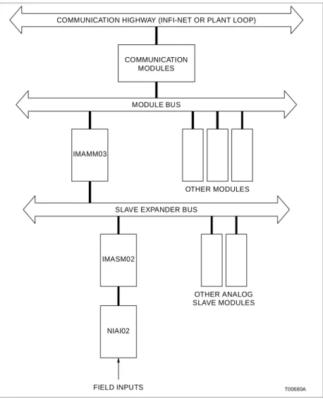
One Thermocouple Input Termination Module (NIAI02) is required for each Thermocouple Slave Module (IMASM02). Each NIAI02 can input eight thermocouple or millivolt signals from field equipment to the thermocouple input slave module. The signals pass through the slave module to the Analog Mas-ter Module (IMAMM03).
This manual explains the purpose, setup, handling precau-tions and steps to install the NIAI02 module.
INTENDED USER
System engineers and technicians should read this manual before installing and using the termination module (TM). Put the module into operation only after reading and understand-ing this instruction. Refer to the Table of Contentsto find the information. Refer to the HOW TO USE THIS MANUAL entry in this section to get started.
MODULE DESCRIPTION
The NIAI02 is a single printed circuit board that uses one slot in a Termination Mounting Unit (NTMU01/02). The termina-tion module (TM) has one card edge connector, P1. It connects to the slave module through a cable. The terminal blocks for field wiring are on the TM. The NIAI02 handles up to 8 couple inputs for the IMASM02. Each input may be thermo-couple or millivolt from -100 to +100 millivolts or 0 to 100 millivolts. Figure 1-1 shows an application example for the NIAI02.
FEATURES
The design of the NIAI02, as with all INFI 90 devices, allows for flexibility in creating a process management system. Refer to the NOMENCLATURE entry of this section for the list of devices that can be used with the TM in an INFI 90 system.
• A standard factory-wired cable connects the TM to the
slave module.
• Connect I/O wires on terminals at the front edge of the TM. • Each TM fits in a standard termination mounting unit. • Field wire termination for eight thermocouple or millivolt
inputs.
• Input signal routing to the IMASM02. • Source of the local cold junction reference.
INTRODUCTION
INSTRUCTION CONTENT
®
INSTRUCTION CONTENT
This manual has five sections and an appendix.
Introduction Contains an overview of the features, description and specifica-tions and a description of the NIAI02.
Installation Describes cautions to observe when handling the TM. It shows the steps to install and connect the terminal wiring before applying power.
Maintenance Provides a maintenance schedule.
Repair/Replacement Procedures
Details how to replace a TM.
Support Services Describes the support services (repair parts, training, docu-mentation, etc.) available from Bailey Controls Company.
Appendix A Shows the cabling needed for the Thermocouple Slave Input Module (IMASM02).
Figure 1-1. Application Example for NIAI02 COMMUNICATION HIGHWAY (INFI-NET OR PLANT LOOP)
MODULE BUS IMAMM03 IMASM02 NIAI02 FIELD INPUTS OTHER MODULES OTHER ANALOG SLAVE MODULES SLAVE EXPANDER BUS
COMMUNICATION MODULES
INTRODUCTION
HOW TO USE THIS MANUAL
HOW TO USE THIS MANUAL
Read this manual before handling the TM. Refer to the sections in this list as needed for more information.
1. Read Section 2 before connecting the NIAI02. 2. Refer to Appendix Afor the IMASM02 slave module. 3. Refer to Section 3 for the maintenance schedule. 4. Refer to Section 4 and Section 5 when needed. GLOSSARY OF TERMS AND ABBREVIATIONS
Table 1-1 contains the glossary of terms for this manual.
REFERENCE DOCUMENTS
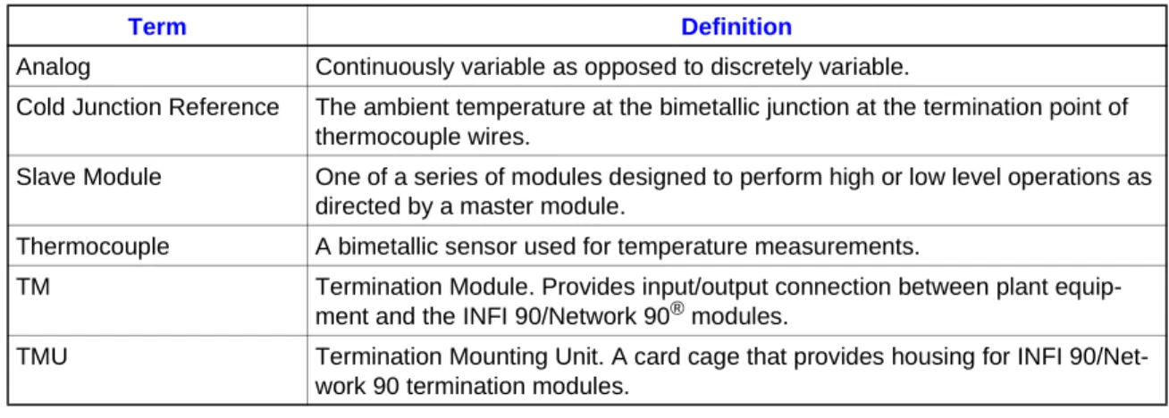
Table 1-2 contains the reference documents for the NIAI02. Table 1-1. Glossary of Terms and Abbreviations
Term Definition
Analog Continuously variable as opposed to discretely variable.
Cold Junction Reference The ambient temperature at the bimetallic junction at the termination point of thermocouple wires.
Slave Module One of a series of modules designed to perform high or low level operations as directed by a master module.
Thermocouple A bimetallic sensor used for temperature measurements.
TM Termination Module. Provides input/output connection between plant equip-ment and the INFI 90/Network 90® modules.
TMU Termination Mounting Unit. A card cage that provides housing for INFI 90/Net-work 90 termination modules.
Table 1-2. Reference Documents Document Number Description
I-E96-205 Analog Master Module and Analog Slave Modules (IMAMM03 and IMASM01/02/03/04)
I-E96-420 Thermocouple Calibration Module (NIAC02) I-E96-437 Analog Master Termination Module (NIAM02) I-E96-500 Site Planning and Preparation
INTRODUCTION
NOMENCLATURE
®
NOMENCLATURE
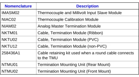
Table 1-3 contains the modules and equipment that can be used with the NIAI02 module:
SPECIFICATIONS
Refer to Table 1-4 for the specifications of the NIAI02 Termina-tion Unit.
Table 1-3. Nomenclature Nomenclature Description
IMASM02 Thermocouple and Millivolt Input Slave Module NIAC02 Thermocouple Calibration Module
NIAM02 Analog Master Termination Module NKTM01 Cable, Termination Module (Ribbon) NKTU02 Cable, Termination Module (PVC) NKTU12 Cable, Termination Module (non-PVC)
258436A1 Cable retaining kit used when a round cable connects to the TMU
NTMU01 Termination Mounting Unit (Rear Mount) NTMU02 Termination Mounting Unit (Front Mount)
Table 1-4. Specifications
Property Characteristic/Value Power Requirements 24 VDC at 10 mA.
Mounting Slides into a single slot in the termination mounting unit NTMU01/02. Environmental
Electromagnetic/
Radio Frequency Interference
No values available at this time. Keep cabinet doors closed. Do not use communication equipment closer than 2 meters from the cabinet. Ambient Temperature 0 to 70oC (32 to 158oF)
Relative Humidity 5% to 90% ± 5% up to 55oC (131oF) (noncondensing). 5% to 40% ± 5% up to 70oC (158oF) (noncondensing). Atmospheric Pressure Sea level to 3 km (1.86 miles).
Air Quality Noncorrosive.
Cooling Requirements No cooling is necessary when used in Bailey Controls cabinets and operated within stated limits.
Surge Protection Meets IEEE-472-1974 Surge Withstand Capability Test1.
Certification CSA certified for use as process control equipment in an ordinary (non-hazardous) location.
NOTE: 1. Do not use the NKTM01 cable when compliance with IEEE-472-1974 is necessary. Specifications are subject to change without notice.
INTRODUCTION
SECTION 2 - INSTALLATION
INTRODUCTION
This section explains how to install the Thermocouple Analog Input Termination Module (NIAI02). Read, understand, and complete the steps in the order they appear before using the NIAI02 module.
SPECIAL HANDLING
Observe these steps when handling electronic circuitry:
NOTE: Always use the Bailey Controls Field Static Kit (part number
1948385A1 - consisting of two wrist straps, ground cord assembly, alligator clip, and static dissipating work surface) when working with modules. The kit is designed to connect the technician and the static dissipating work surface to the same ground point to prevent dam-age to the modules by electrostatic discharge.
Use the static grounding wrist strap when installing and removing modules. Static discharge may damage MOS devices on modules in the cabinet. Use grounded equipment and static safe practices when working with modules.
1. Use Static Shielding Bag. Keep the modules in the static shielding bag until you are ready to install them in the system. Save the bag for future use.
2. Ground Bags Before Opening. Before opening a bag con-taining an assembly with CMOS devices, touch it to the equip-ment housing or ground to equalize charges.
3. Avoid Touching Circuitry. Handle assemblies by the edges; avoid touching the circuitry.
4. Avoid Partial Connection of CMOS Device.Verify that all devices connected to the modules are properly grounded before using them.
5. Ground Test Equipment.
6. Use Antistatic Field Service Vacuum. Remove dust from the module if necessary.
7. Use Grounded Wrist Strap. Connect the wrist strap to the appropriate grounding plug on the power entry panel. The grounding plug on the power entry panel is connected to the cabinet chassis ground.
INSTALLATION
UNPACKING AND INSPECTION
®
UNPACKING AND INSPECTION
These are steps to follow for general handling:
1. Examine the module to make sure that no damage has occurred in transit.
2. Notify the nearest Bailey Controls sales office of any damage. 3. File a claim for any damage with the shipping company that handled the shipment.
4. Use the original packing material or container to store the module.
5. Store the module in a place with clean air; free of extremes of temperature and humidity.
SETUP/PHYSICAL INSTALLATION
This section explains how to configure and install the NIAI02. The required procedures are installing the termination module into the TMU, and connecting the field wiring and communica-tion cables.
Cable Connections
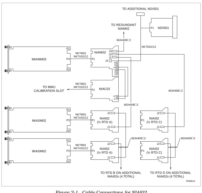
Before installing the IMASM02, connect either the NKTM01 or NKTU02/12 termination cable. Figure 2-1 shows the cabling for the NIAI02 to the IMASM02 and NIAM02.
Install the termination module cable (NKTM01 or NKTU02/ NKTU12) to connect the TM to the slave. The NKTM01 is a flat ribbon cable. The NKTU02 is a round, shielded cable with PVC jacket. The NKTU12 is a round, shielded cable with non-PVC jacket.
NIAI02 modules can be interconnected through ribbon cable part number 6634408A2 supplied with the NIAI02. Up to eight NIAI02 TMs can connect to a single master module through a NIAM02 master termination module.
NOTE: The NIAM02 is used to connect NIAI02 TMs to the
IMAMM03 master for local cold junction compensation. The NIAI02 TMs for slaves 1 to 4 connect to J1 of NIAM02, and NIAI02 TMs for slaves 5 to 8 connect to J2 of the NIAM02.
Cable Installation
The NKTU02/12 and NKTM01 cable connects the NIAI02 to the IMASM02 slave module. The NIAM02 master termination mod-ule connects to the NIAI02 through the 6634408A2 ribbon cable. Table 2-1 lists the NIAI02 cable applications.
INSTALLATION
SETUP/PHYSICAL INSTALLATION
Figure 2-1. Cable Connections for NIAI02 Table 2-1. NIAI02 Cable Applications Nomenclature/
Description Application Connector
Maximum Length NKTU02
(PVC Jacket)
Connects NIAI02 to IMASM02. P1 on TM to MMU backplane. 61 m (200 ft) NKTU12 (non-PVC
Jacket)
NKTM01 (ribbon) Connects NIAI02 to IMASM02. P1 on TM to MMU backplane. 30 m (100 ft) 6634408A2 (one
rib-bon cable is shipped with each NIAI02)
Connects NIAI02 to NIAI02. J2 on TM1 to J1 on TM2.
0.61m (2 ft) Connects NIAM02 to NIAM02. J3 on TM1 to J3 on TM2.
Connects NIAM02 to NIAI02 1 thru 4.
J1 on NIAM02 to J1 on NIAI02. Connects NIAM02 to NIAI02
5 thru 8. J2 on NIAM02 to J1 on NIAI02. IMASM02 IMASM02 IMAMM03 P1 P1 P1 NKTM01 NKTU02/12 NKTM01 NKTU02/12 NKTM01 NKTU02/12 NKTM01 NKTU02/12 P2 P2 P2 P3 P3 P3 P1 P1 P1 J1 J1 J1 J2 J2 J4 6 5 +4 –3 2 1 J2 J1 J3 +2 –1 J2 P1 P1 P1 TO RTD B ON ADDITIONAL NIAI02s (4 TOTAL) NIAI02 (½ RTD A) P1 J1 J2 NIAI02 (½ RTD C) NIAI02 (½ RTD A) NIAC02 NIAM02 NDIS01 NIAI02 (½ RTD C) TO RTD D ON ADDITIONAL NIAI02s (4 TOTAL) T00681A 6634408 2 6634408 2 NKTD02/12 6634408 2 TO MMU CALIBRATION SLOT TO REDUNDANT NIAM02 TO ADDITIONAL NDIS01 6634408 2 6634408 2
INSTALLATION
SETUP/PHYSICAL INSTALLATION
®
To install the cable follow these steps:
1. Pull the termination module several inches from the TMU backplane.
2. If round type cables are already installed in the TMU, remove the cable retaining bracket (Bailey part number 258436A1). Use NKTU02/12 or NKTMU01 cables. Round cables and ribbon cables can be mixed when installing multi-ple TMs.
3. Insert the J2 end of the termination module cable into the MMU backplane slot assigned to the slave module. The cable should latch securely in place. Card edge connector P3 of the slave module connects to this end of the cable.
4. If NKTU02 or NKTU12 cables are used, connect the shield wire extending from the J2 end of the cable to the shield bar. 5. Insert the J1 end of the cable into the TMU backplane slot assigned to the NIAI02 module. The cable should latch securely in place. Card edge connector P1 of the NIAI02 module connects to this end of the cable.
6. Up to four NIAI02 TMs (1-4) can be interconnected by con-necting J2 on the first TM to J1 on the second TM with ribbon cable part number 6634408A2. Install the 6634408A2 cable for each NIAI02.
7. Connect J1 of the first NIAI02 in the interconnection with TM-1 through TM-4 to J1 on the NIAM02.
8. Up to four additional NIAI02 TMs (5-8) can be intercon-nected by connecting J2 on the first TM to J1 on the second TM with ribbon cable part number 6634408A2. Install the 6634408A2 cable for each NIAI02.
9. Connect J1 of the first NIAI02 in the interconnection with TM-5 through TM-8 to J2 on the NIAM02.
10. Replace or add the cable retaining bracket if round type cables are installed in the TMU.
CAUTION
Remove modules from their assigned slots before installing a cable to that slot. Failure to do so could result in damage to the module or station.
ATTENTION
Retirer les modules de leur position assignée avant d'installer un câble à cette position. Des dommages au module ou au poste pourraient résulter d'un manquement à cette procédure.
INSTALLATION
SETUP/PHYSICAL INSTALLATION
Termination Module Installation
The NIAI02 inserts into a standard INFI 90 termination mount-ing unit (TMU) and occupies one slot. To install:
1. Verify slot assignment of the NIAI02 module.
2. Align the NIAI02 module with the guide rails in the TMU and partially insert the module. Leave enough room to connect terminal wiring and cables.
Completely seat the module after cabling and termination wir-ing is attached.
Terminal Wiring
Connect the wiring from the thermocouple or millivolt signal sensing the process to the termination module terminals. For new installations, refer to the Site Planning and Preparation manual for information on I/O wiring.
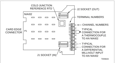
Figure 2-2 shows the terminal assignments for each input and a field input termination example.
CAUTION It is strongly recommended that all power (cabinet, I/O, etc.) be turned off before doing any termination module wiring. Failure to do so could result in equipment damage. Do not apply power until all connections are verified.
ATTENTION Ll est fortement recommande que toutes les alimentations (armoire, E/S, etc.) soient coupees avant d'effectuer quelque raccord que ce soit sur une carte de raccordement. Un man-quement a ces instructions pourrait causer des dommages a l'equipment. Ne pas rebrancher les alimentations avant d'avoir verifie tous les raccordements.
Figure 2-2. Terminal Assignments for NIAI02 CARD EDGE
CONNECTOR
COLD JUNCTION
REFERENCE RTD J2 SOCKET (OUT) TERMINAL NUMBERS CHANNEL NUMBERS TYPICAL CONNECTION FOR A THERMOCOUPLE TO AN NIAI02 TYPICAL CONNECTION FOR A DIFFERENTIAL MILLIVOLT INPUT TO AN NIAI02 J1 SOCKET (IN) T00682A NIAI02 P1 16 1 9 8 16 1 9 8 16 14 12 10 8 6 4 2 + 15 13 11 9 7 5 1 1 – + – + – + – + – + – + – + – + – 8 7 6 5 4 3 2 1
INSTALLATION
SETUP/PHYSICAL INSTALLATION
®
Power Wiring
Connect field inputs with 14 to 22 gauge wire. To connect field wiring follow these steps:
1. Remove the front cover.
2. Ensure the NIAI02 module is pulled out far enough to gain access to the terminal strip.
3. Feed the field wiring into the terminal strip area and con-nect them to the appropriate terminals.
4. Insert the module until it locks securely into place.
5. Replace the front cover to maintain thermal stability for the local cold junction reference RTD.
The NIAI02 is ready for operation if:
1. The circuit board is mounted in the termination mounting unit.
2. All required cables are connected to the termination mod-ule.
3. All required field wires are connected to the termination module.
CAUTION If input or output circuits are a shock hazard after disconnect-ing system power at the power entry panel, then the door of the cabinet containing these externally powered circuits must be marked with a warning stating that multiple power sources exist.
ATTENTION Si des circuits d'entree ou de sortie sont alimentes a partir de sources externes, ils presentent un risque de choc electrique meme lorsque l'alimentation du systeme est debranchee du panneau d'entree l'alimentation. Le cas echeant, un avertisse-ment signalant la presence de sources d'aliavertisse-mentation multiples doit etre appose sur la porte de l'armoire.
INTRODUCTION
SECTION 3 - MAINTENANCE
INTRODUCTION
The Analog Input Termination Module (NIAI02) requires limited maintenance. This section contains a maintenance schedule. MAINTENANCE SCHEDULE
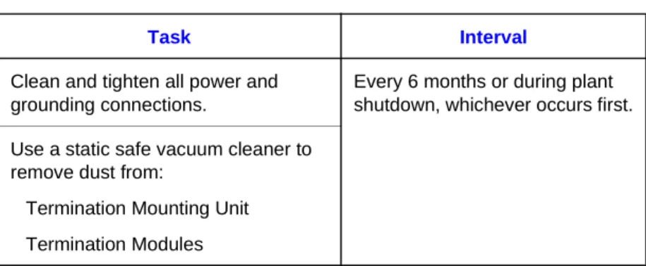
Execute the tasks in Table 3-1 at the specified intervals. Table 3-1. Maintenance Schedule
Task Interval
Clean and tighten all power and grounding connections.
Every 6 months or during plant shutdown, whichever occurs first. Use a static safe vacuum cleaner to
remove dust from:
Termination Mounting Unit Termination Modules
INTRODUCTION
SECTION 4 - REPAIR/REPLACEMENT PROCEDURES
INTRODUCTION
This section explains the replacement procedures for the Ana-log Input Termination Module (NIAI02). No special tools are required to replace the module.
REPLACEMENT PROCEDURES
If a NIAI02 is faulty, replace it with a new one. Do not try to repair the module. Replacing components may affect perfor-mance and certification.
To replace a NIAI02 termination module:
1. Remove the termination module front cover.
2. Pull the termination module several inches from the TMU backplane.
3. Label and remove all power and field wiring from the termi-nal blocks.
4. Slide the TM out of the TMU.
5. Slide the new TM into the same slot as the module that was removed.
CAUTION It is strongly recommended that all power (cabinet, I/O, etc.) be turned off before doing any termination module wiring. Failure to do so could result in equipment damage. Do not apply power until all connections are verified.
ATTENTION Ll est fortement recommande que toutes les alimentations (armoire, E/S, etc.) soient coupees avant d'effectuer quelque raccord que ce soit sur une carte de raccordement. Un man-quement a ces instructions pourrait causer des dommages a l'equipment. Ne pas rebrancher les alimentations avant d'avoir verifie tous les raccordements.
CAUTION Remove modules from their assigned slots before installing a cable to that slot. Failure to do so could result in damage to the module or station.
ATTENTION Retirer les modules de leur position assignée avant d'installer un câble à cette position. Des dommages au module ou au poste pourraient résulter d'un manquement à cette procédure.
REPAIR/REPLACEMENT PROCEDURES
REPLACEMENT PROCEDURES
®
6. Connect all power and field wiring removed in Step 3. 7. Verify that wiring and cabling to the TM is correct. 8. Fully insert the termination module into the TMU. 9. Replace the termination module front cover.
10. Turn on the cabinet power supply that provides power to the TM.
INTRODUCTION
SECTION 5 - SUPPORT SERVICES
INTRODUCTION
Bailey Controls Company is ready to help in the use, applica-tion and repair of its products. Contact the nearest sales office to make requests for sales, applications, installation, repair, overhaul and maintenance contract services.
REPLACEMENT PARTS AND ORDERING INFORMATION
When making repairs, order replacement parts from a Bailey Controls sales office. Provide this information:
1. Part description, part number and quantity. 2. Model and serial numbers (if applicable).
3. Bailey instruction manual number, page number and refer-ence figure that identifies the part.
Order parts without commercial descriptions from the nearest Bailey Controls Company sales office.
TRAINING
Bailey Controls Company has modern training facilities that provide service and repair instruction. On-site training is also available. Contact a Bailey Controls Company sales office for specific information and scheduling.
TECHNICAL DOCUMENTATION
Additional copies of this manual, or other Bailey Controls Com-pany manuals, can be obtained from the nearest Bailey Con-trols Company sales office at a reasonable charge.
INTRODUCTION
APPENDIX A - THERMOCOUPLE SLAVE INPUT MODULE
(IMASM02)
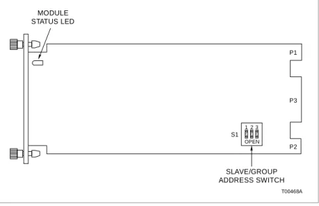
INTRODUCTIONThe Thermocouple Analog Slave Input Module (IMASM02) uses an NIAI02 for termination of field wiring. Each NIAI02 accepts up to eight thermocouple or millivolt inputs. This appendix contains figures and tables that show the dipswitch location on the IMASM02 and its settings. This information is provided as a quick reference guide for personnel installing the NIAI02. Fig-ure A-1 shows the address select switch (SW1). Table A-1 lists the binary addresses for setting SW1. Refer to the IMAMM03 instruction for more detailed information to install and config-ure the slave.
Figure A-1. Address Select Switch (SW1) Table A-1. Address Switch Settings (SW1) Addr MSB LSB Addr MSB LSB 1 2 3 1 2 3 0 0 0 0 4 1 0 0 1 0 0 1 5 1 0 1 2 0 1 0 6 1 1 0 3 0 1 1 7 1 1 1 OPEN = OFF = 1 CLOSED = ON = 0 T00468A P2 P3 P1 MODULE STATUS LED SLAVE/GROUP ADDRESS SWITCH S1 2 1 OPEN 3
Index
A
Address select switch (SW1)... A-1 Address switch settings (SW1)... A-1 Application example for NIAI02 ... 1-2
C
Cable connections for NIAI02... 2-3
G
Glossary of terms and abbreviations ... 1-3
I
Input circuit for NIAI02 ... 2-5
M
Maintenance schedule ... 3-1
N
NIAI02 cable applications ... 2-3 Nomenclature ... 1-4
R
Reference documents... 1-3 Replacement parts... 5-1 Replacement procedures... 4-1S
Setup/physical installation... 2-2 Cable connections... 2-2 Cable installation ... 2-2 Power wiring... 2-6 Terminal wiring ... 2-5 Termination module installation ... 2-5 Special handling... 2-1 Specifications ... 1-4T
Technical documentation ... 5-1 Terminal assignments for NIAI02... 2-5 Training ... 5-1
U
Visit Elsag Bailey on the World Wide Web at http://www.bailey.com
Our worldwide staff of professionals is ready to meet your needs for process automation. For the location nearest you, please contact the appropriate regional office.
AMERICAS
29801 Euclid Avenue Wickliffe, Ohio USA 44092 Telephone 1-216-585-8500 Telefax 1-216-585-8756 ASIA/PACIFIC 152 Beach Road Gateway East #20-04 Singapore 189721 Telephone 65-391-0800 Telefax 65-292-9011
EUROPE, AFRICA, MIDDLE EAST
Via Puccini 2 16154 Genoa, Italy Telephone 39-10-6582-943 Telefax 39-10-6582-941 GERMANY Graefstrasse 97 D-60487 Frankfurt Main Germany Telephone 49-69-799-0 Telefax 49-69-799-2406
Form I-E96-434A Litho in U.S.A. 592
Copyright © 1992 by Elsag Bailey Process Automation, As An Unpublished Work ® Registered Trademark of Elsag Bailey Process Automation