1
rrrnnrn1
0000086938ROBUST AND RELIABLE DUAL TIRE CLASSIFICATION SYSTEM WITH ERROR COMPENSATION MODULE
AHMAD NASIRUDDIN AB RAZAK
THIS THESIS IS SUBMITTED IN FULFILMENT OF THE REQUIREMENTS FOR THE DEGREE OF MASTER OF SCIENCE
FACULTY OF ENGINEERING AND BUILD ENVIRONMENT UNIVERSITI KEBANGSAAN MALAYSIA
BANG I
G; I f/11/llJ PERPUSTAKAAN 2014 UNIVERSITI MALAYSIA PAHANG
No. Perolehan No. Panggilan
086838
T:J~~
Tarikh -N -~
)<l )L}
.
0 1
JUL
£u1i
"\,jJ\j '('lV
ABSTRACT
The toll industry put great emphasis on preventing revenue leakage especially from fraud by toll tellers. An automatic vehicle classification system (A VC) has been developed in order to mitigate the problem based on the classes defined by Malaysian Highway Authority (MHA). The system uses treadle sensors to map tires and count the number of axles while the optical barrier is used to detect the presence of vehicle. However, since the short lifecycle because of wear and tear due to the nature of them being treaded by the vehicles, the treadle breaks quickly and needs frequent replacement. Disruptions during maintenance and replacement causing inconvenience and unreliability that results in a steady demand by worldwide toll collection industries for replacement or at least enhancement of the technology. Two approaches have been made to mitigate this problem. First, the materials in the treadle are improved and second, a system to compensate for small errors is developed. The sensor is changed from fragile contact switch to strain gage that has high fatigue limit. The new sensor housing is made out of stainless steel that has high fatigue limit of 260 MPa. Furthermore, to increase the treadle endurance, the sensors are contained in elastomeric material which possesses hardness of 70 (Shore A scale) that protects the sensors from external impact of vehicles yet still allows force to be transferred to the sensor. The new treadle sensor was tested and can last more than 5 million treading cycles as required by the industry. Moreover, a robust dual tire classification module is installed in the system that can maintain high accuracy even when some sensors have error. Test using simulated data shows that the algorithm can maintain 100% accuracy when two errors are present. The module was also tested on actual data that gives 99.83% accuracy. With these enhancements, the lifecycle of the device is elongated beyond 5 million cycles without compromising the accuracy. Thus, it prevents revenue leakage and avoids traffic disruptions that will contribute positively to the economy.
v
SISTEM PENGELASAN TAYAR BERGANDA YANG TEGUH DAN BOLEH HARAP DENGAN MODUL PEMBETULAN RALAT
ABSTRAK
Industri tol sangat menekankan kepada pencegahan kebocoran basil terutamanya daripada pengutipan tol. Sebuah sistem pengelasan kenderaan automatik telah dibangunkan dengan tujuan untuk mengatasi masalah tersebut bersandarkan kepada kelas kenderaan yang ditetapkan oleh Lembaga Lebuhraya Malaysia (LLM). Sistem tersebut menggunakan penderia injak-injak untuk memeta corak tayar dan mengira
jumlah gandar manakala penghadang optik digunakan untuk mengesan kehadiran kenderaan. W alaubagaimanapun, memandangkan kitaran hid up yang pendek yang disebabkan haus dan lusuh kerana tabiinya yang sentiasa digelek kenderaan, injak-injak tersebut ·cepat rosak dan perlu diganti selalu. Gangguan ketika penyenggaraan menyebabkan kesulitan dan ketidakbolehharapan dan ini menuntut industri tol di
seluruh dunia untuk menghasilkan kaedah yang lebih efektif untuk mengganti atau menambahbaik teknologi yang sedia ada. Dua pendekatan telah diambil untuk
mengatasi masalah ini. Pertama, menambahbaik bahan-bahan untuk membuat injak-injak dan yang kedua, membangunkan sebuah sistem pembetulan bagi ralat kecil.
Penderia tersebut telah ditukar daripada suis sentuhan yang mudah rosak kepada jenis tolok terikan yang mempunyai had lusuh yang tinggi. Penutup penderia itu telah dibuat daripada keluli tahan karat yang mempunyai batas Iesu tinggi iaitu 260 MPa. Manakala, penderia itu diselaputi oleh bahan elastomerik dengan kekerasan 70 (skala
Shore A) yang melindunginya daripada impak luaran oleh kenderaan tetapi masih membenarkan daya untuk dipindahkan kepada penderia itu. Penderia tersebut boleh bertahan lebih daripada 5 juta kitaran injakan seperti yang dikehendaki oleh industri.
Tambahan pula, sebuah modul pengelasan tayar berganda yang teguh telah
dipasangkan kepada sistem yang boleh mengekalkan kejituan yang tinggi walaupun
terdapat beberapa penderia yang mempunyai ralat. Ujian menggunakan data simulasi
menunjukkan yang algoritma tersebut dapat mengekalkan kejituan 100% walaupun wujud dua penderia yang mempunyai ralat. Modul tersebut juga telah diuji dengan data sebenar yang mana memberikan kejituan 99.83%. Dengan pena mbahbaikan-penambahbaikan ini, kitaran hidup peranti tersebut dapat dipanjangkan melebihi 5 juta kitaran tanpa berkompromi dengan kejituan. Justeru, ia mencegah kebocoran hasil dan mengelakkan gangguan trafik yang mana menyumbang secara positif kepada ekonomi.
CONTENT DECLARATION ACKNOWLEDGEMENT ABSTRACT ABSTRAK CONTENT LIST OF TABLES LIST OF FIGURES LIST OF ABBREVIATIONS LIST OF SYMBOLS CHAPTER I 1.1 1.2 1.3 1.4 1.5 CHAPTER II 2.1 2.2 2.3 INTRODUCTION Background Problem Statement Objectives Scope of work Thesis Organization LITERATURE REVIEW Introduction
Malaysia Vehicle Class
Dual Tire Detector Technology
Vl Page 11 lll lV v Vl IX x XIV xv 1 3 4 4 5 7 7 8 2.3.1 Camera 9 2.4 2.5 2.6 2.3.2 Treadle 10
2.3 .3 Treadle Tactile Sensor Technology Fatigue 15 Limit Assessment
Dual Tire Classification System 2.4.1 Independent Tire Classification 2.4.2 Relative Tire Classification
Error Detection And Error Compensation Module Micro Invention Technology Description
2.6.1 Micro Invention A VC System Overview
16 17 17 19 19 20
2.7 CHAPTER III 3.1 3.2 3.3 3.4 3.5 CHAPTER IV 4.1 4.2 4.3 4.4 4.5 4.6 4.7 CHAPTERV 5.1 5.2
2.6.2 Micro Invention Dual Tire Detector
2.6.3 Micro Invention Dual Tire Classification System Summary
SENSOR HARDWARE DEVELOPMENTS Introduction
Switch Arrangement Strain Gage As A Switch
3.3.l Introduction to strain gage
3.3.1 Strain Gage Pairing Scheme Circuit Network 3.3.3 Strain Gage Housing
3.3.4 Strain Gage Contact Mechanism 3.3.5 Treadle Filler
Endurance Test
3.4.1 Three Point Bending Test
3.4.2 Endurance Test with Real Tire and Treadle Casing Summary
DUAL TIRE CLASSIFICATION SYSTEM Introduction
Proposed DTC System Error Detection Module
4.3.1 Error Detection Algorithm 4.3.2 Template Matching Application Error Compensation Module
Tire Classification Module
4.5.1 Euclidean Distance Algorithm
4.5.2 Radial Basis Function Neural Network Algorithm Dual Tire Classification System Evaluation Test
4.6.1 Simulation Data Test 4.6.2 Field Data Test Summary
RESULTS AND DISCUSSIONS Introduction
Sensor Hardware Development Analysis
Vll 22 23 24 25 29 29 30 32 33 35 36 37 37 38 41 42 42 46 46 47 53 55 55 59 61 62 63 63 64 64
5.3 5.4 CHAPTER VI 6.1 6.2 REFERENCE APPENDICES A B
c
D E F G5.2.1 Strain Gage as a Switch Analysis 5.2.2 Polyurethane Optimal Ratio Analysis 5.2.3 Switch Arrangement Analysis
5.2.4 Sensor Endurance Test Analysis Dual Tire Classification System Analysis 5.3.1 Field Test Analysis
5.3.2 Proposed DTC System Modules Analysis Summary
CONCLUSIONS & FUTURE WORKS
Conclusions
Future Works
Total Highway Traffic for Year 2009 and Year 2010 Micro Invention Dual Tire Detector Catalog
Treadle Prototype Production
Treadle Interface to the AVC System Treadle Casing Drawing
Tire Standards and Tread Width Estimation
Published Paper Vlll 64 66 67 68 75 75 78 84 86 87 89 93 94 95
99
103 104 106Table No. 2.1 2.2 2.3 3.1 3.2 5.1 5.2 5.3 5.4 5.5 5.6 5.7 LIST OF TABLES
Vehicle classes in Malaysia
Functions and mechanism of each sensors in MI AVC system
Summary of Micro Invention tire classification algorithm
Survey of dual tire tread-to-tread spacing
Tensile properties of SS316L and SS304 Polyurethane optimal ratio test
Strain gage and SS3 l 6L condition after three-point bending test
Comparisons of performance between the different methods
The processing time for SqEDI and SmEDI algorithm to identify errors
Dual tire classification accuracy rate after permanent OFF error is introduced
Dual tire classification accuracy rate after permanent ON error
is introduced
Dual tire classification accuracy rate after ECM IS implemented IX Page 8 21 23 27 33 66 68 79 81
83
84 84Figure No. 2.1 2.2
2.3
2.42.5
2.6 2.7 2.8 2.92.10
2.112.12
2.13 2.142.15
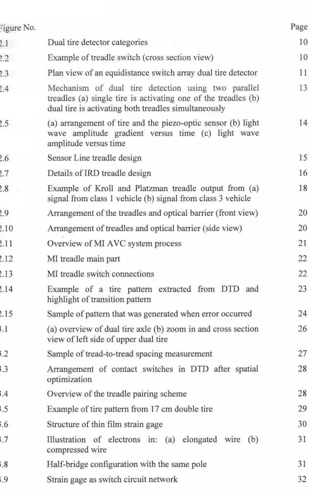
3.1 3.2 3.3 3.4 3.5 3.6 3.7 3.8 3.9 LIST OF FIGURESDual tire detector categories
Example of treadle switch (cross section view)
Plan view of an equidistance switch array dual tire detector
Mechanism of dual tire detection using two parallel
treadles (a) single tire is activating one of the treadles (b)
dual tire is activating both treadles simultaneously
(a) arrangement of tire and the piezo-optic sensor (b) light wave amplitude gradient versus time ( c) light wave amplitude versus time
Sensor Line treadle design Details of IRD treadle design
Example of Kroll and Platzman treadle output from (a)
signal from class 1 vehicle (b) signal from class 3 vehicle Arrangement of the treadles and optical barrier (front view) Arrangement of treadles and optical barrier (side view) Overview of MI AVC system process
MI treadle main part
MI treadle switch connections
Example of a tire pattern extracted from DTD and highlight of transition pattern
Sample of pattern that was generated when error oc~urred (a) overview of dual tire axle (b) zoom in and cross section
view of left side of upper dual tire
Sample of tread-to-tread spacing measurement
Arrangement of contact switches in DTD after spatial optimization
Overview of the treadle pairing scheme
Example of tire pattern from 17 cm double tire Structure of thin film strain gage
Illustration of electrons in: (a) elongated wire (b)
compressed wire
Half-bridge configuration with the same pole Strain gage as switch circuit network
x Page 10 10 11 13 14 15 16 18
20
20
21 2222
23
24 26 27 28 28 29 30 31 3132
Xl
3.10 Stainless steel 316L measurements and bending orientation 34 3.11 Drawing of strain gage mounted on stainless steel plate 34
3.12 Cross section view of stainless steel housing inside a 35
treadle
3.13 Treadle contact mechanism 35
3.14 Block diagram of contact mechanism 36
3.15 Treadle filler samples with various ratios of polyurethane 36 and hardener
3.16 Durometer with shore A scale 37
3.17 Three-point bending test setup 37
3.18 Drawings of the jig components and treadle casing 38
3.19 Experiment setup for endurance test with real tire and 39 treadle
3.20 Field test at UKM Gate Two 40
3.21 Experimental set up for the field test 40
3.22 HBM CANHEAD Direct with 20 channels 40
4.1 Overview of DTC system configuration 43
4.2 Flow chart of dual tire classification system 45
4.3 Example of tire patterns that contain error 46
4.4 Some examples of single tire pattern compilation (a) single 48 tire patterns start at first position (b) single tire patterns
start at second position ( c) single tire patterns start at thirteenth position
4.5 Block diagram of the process to prepare permanent OFF 48 error pattern database
4.6 Examples of non-useful and useful tire patterns 49
4.7 Block diagram of modification to prepare database for 50 second error detection
4.8 Block diagram of modification to prepare database for third 50 error detection
4.9 Column and row batch that is related to switch 2 is erased 51 and reduced
4.10 Flow chart of error detection module 52
4.11 Flow chart of error compensation module 53
4.12 Input from DTD is modified to compensate the error from 53 switch 6
XU
4.13 Illustration of section width and tread width from tire cross 54
section
4.14 Case study showing Euclidean distance method maintains 56 the tread-to-tread spacing information
4.15 Example of single tire pattern mistakenly classified as dual 56 tire
4.16 Example of (a) the Euclidean distance of dual tire vehicle 57 without align algorithm (b) the Euclidean distance of dual
tire vehicle after align algorithm is implemented
4.17 The align algorithm flow chart for skewed data 58
4.18 Flow chart of dual tire classification using Euclidean 59 distance algorithm
4.19 An overview of the RBFNN architecture for dual tire 61 classifier
4.20 Example of error simulation implemented to single tire 62
pattern taken from Figure 4.4; OFF error at switch 3 and ·
ON error at switch 10.
5.1 Demonstration of dual tire treading on different part of the 67 equidistance switch (a) tread-to-tread spacing starts at the
beginning of sensor. (b) tread-to-tread spacing starts at the middle of sensor. ( c) tread-to-tread spacing starts at the end of sensor
5.2 Cyclic stress graph for 2.0 mm test displacement 69
5.3 Cyclic stress graph for 2.5 mm test displacement 69
5.4 Cyclic stress graph for 4.0 mm test displacement 70
5.5 Strain experienced by strain gage from a 10 metric ton bus 71 5.6 Strain-time plot of the three channels for the first treadle 72
sample
5.7 Strain vs. cycle plot for the first treadle sample 72
5.8 Illustration of endurance test setup for the first sample 73
5.9 Strain-time plot of the two channels for second sample 74 5.10 Strain vs. cycle plot for the second treadle sample 75
5.11 Example of 3D plot of tire pattern from a car 76
5.12 The corresponding tire pattern from the car 76
5.13 Example of 3D plot of tire pattern from a bus 76
5.15
5.16
5.17
Tire patterns that are misclassified by Micro Invention's method (a) single tire classified as dual tire with OFF error (b) single tire classified as dual tire with ON error ( c) dual tire classified as single tire with ON error (d) dual tire
classified as single tire with OFF error (e) dual tire classified as single because of various possible reasons:
vehicles moving too fas~ and evading the treadle, very wide dual tire, prduction flaw and others.
Tire pattern that is misclassified by Euclidean distance method
Tire pattern that contains error at switch 2 and 4
Xlll
80
80
3D AVC BHD Co. CPU DAQ DTC DTD ECM EDM exp GmBH I/O L LED LLM MHA MI OB Op Amp PLUS PU RBFNN SDN SmEDI Sq EDI SS SUV
UKM
UTM LIST OF ABBREVIATIONS Three dimensionsAutomated Vehicle Classification Berhad (Limited)
Corporation
Central processing unit Data acquisition Dual tire classification Dual Tire Detector
Error compensation module Error detection module Exponential
Gesellschaft mit beschrankter Haftung (Limited) Input output
Low carbon
Light emitting diode
Lembaga Lebuhraya Malaysia Malaysian Highway Authority Micro Invention
Optical barrier Operational_ amplifier
Projek Lebuhraya Usahasama Berhad Polyurethane
Radial Basis Function Neural Network Sendirian (Private)
Simultaneous error detection and identification Sequential error detection and identification Stainless Steel
Sports utility vehicle
Universiti Kebangsaan Malaysia Universal Testing Machine
A b f() GHz h Hz kN kPa K L l m mm MP a N q R
Ro
s SG t T Vin Voutw
Wqx
xv LIST OF SYMBOLSValue to determine spread of RBF curve
Durometer scale that is commonly used to measure polymer hardness
Distance between input and center of RBF centimeter
Center of radial basis function at number q
Network simulation function
Giga Hertz Hidden layer Hertz Kilo Newton Kilo Pascal Gage factor Low carbon
The narrowest significant width meter
millimeter Mega Pascal
Total number of hidden nodes
Sequence of weight Resistance
Strain gage resistance
seconds
Strain gage
Tire pattern output
Matrix form of tire pattern output External voltage
Input Voltage
Output Voltage
Matrix form of network weight
Weight at number q
a
me:
E
Matrix of all possible tire patterns and positions Matrix of
a
with column 1 is zeroedMatrix of error data strain
milistrain
Matrix of useful error data
Matrix of useful error data for all positions
Matrix form of radial basis function Radial basis function
Ohm
CHAPTER I
INTRODUCTION
1.1 BACKGROUND
Highway authorities around the world have been using toll collection as a way to fund cost related to highway maintenance and expansion. This method is becoming more popular as they realized that the cost is increasing while tolling is a sustainable, stable and dedicated system for highway development. The revenue from toll is also used by government to develop other infrastructures in other less developed regions. This scheme helps to include more regions in the wealth circulation. Some governments may also use toll as leverage for development of private sector (Lindsey 2009). In Malaysia for example, technology based company such as Micro Invention, Hoptech and Touch n' Go are prospering and bringing positive impact on the economy and technology of this country.
There are three basic methods for toll collection that are practiced worldwide: manual toll, electronic toll and mixed toll. Manual tolling is the earliest method practiced by the toll concessionaire. In this method, toll booths are built on the highway and toll teller is appointed in each booth to collect and record the vehicle classes. The operation is slow but it can be mitigated by operating multiple lanes. Electronic toll is an automated system that either identifies or classifies vehicles, and charges them accordingly. The method is faster than manual toll but requires advance technology to operate successfully. Meanwhile, mixed tolling comprises of both manual toll and electronic toll as practiced in Malaysia (The World Bank Group).
There are mainly two systems that are implemented in toll operation. The first
one is Automated Vehicle Classification (AVC) system. This particular system
basically classifies vehicles into several classes based on the policies that are enforced by highway authorities. The classes are defined based on various parameters such as number of axle, number of tire, type of services, number of occupancy, weight and vehicle type. Many researches were conducted to automatically identify the classes using apparatus such as microphone, video camera, treadle, laser, infrared camera and metal loop. Usually this particular system integrates multiple apparatus in order to enhance its performance. The AVC system that proven to be reliable and robust was implemented and commercialized.
Another electronic toll system is Automated Vehicle Identification (AVI) system. Tags or transponders that are ·placed at vehicle windshield contain specific information regarding the vehicle class and its owner. The advancement of radio frequency identification technology made toll charging possible at highway speed. If the vehicle does not possess the transponder, the system will capture the license number image and track the user later (407 Express Toll Route 2010).
Drivers that uses manual toll pay their toll fee by cash or electronic bank card. For electronic toll, the toll fee is either pre-paid or charged monthly based on their usage like electric bill. AVC system is used by both toll collecting methods. In manual toll it is used for auditing while in electronic toll it is used for real-time classification. Toll operators put great emphasis on the accuracy and reliability of the system to ensure that there is no revenue leakage. Therefore, significant investment has been put at toll lane and toll plazas to achieve zero fraud (Monahan 2007).
Accuracy is greatly emphasized and margin of error is difficult to be tolerated in toll system. This is because a small percentage of error can contribute to huge revenue lost due to the high traffic volume. According to Malaysian Highway Authority (MHA), total highway traffic in 2010 is 1.4 billion vehicles (for more detail, refer to Appendix A). Let say if the error rate is 1 %, the total vehicle that will be misclassified is 140 million. This shows the magnitude of the value that could have been lost due to poor accuracy.
3
AVC system usually comprises of sensor called treadle that is embedded in the road surface. However, due to its nature being extensively treaded, especially by the heavy weight vehicles, it wears off quickly and needs frequent replacement. Disruptions during replacement and maintenance are causing inconvenience and unreliability. As a result, there is steady worldwide demand to have replacement of technology or at least enhancement of it (Mirchandani & Head 2001; Mirchandani & Wang 2005).
1.2 PROBLEM STATEMENT
Treadles are sensors that are embedded in the road surface. It could function as axle sensor, dual tire detector (DTD), weigh sensor or speed sensor. When vehicle tire tread on the treadle, the force from vehicle will activate the sensor and produce output that will be used by A VC system to determine the vehicle class. Treadle design usually in the shape of a long bar that would cover the width of a single road pavement. The thickness of the treadle is usually in the range of 1.5 cm to 2 cm but the brute force that it would have to endure from heavy weight vehicles such as trailers and trucks do not match its size.
The treadle developed by Micro Invention (Ml) Sdn Bhd functions as dual tire detector. It detects dual tire accurately but the treadle sensor that they manufactured has poor endurance and reliability. This challenge is not only faced by MI but most of treadle manufacturers around the world (Rosakranse & Emirick 1994; Park & Jeong 2001). This occurs mainly because the treadle was made of fragile components that break quickly under the harsh environment. There are multiple layers of components inside the treadle that scrape with one another while moisture and sand grains could creep inside it and damage the treadle. According to Ml, their treadle could endure until 3 million treading cycles while their targeted life cycle of a treadle is at least 5 million treading cycle. Other manufacturers such as Sensor Line GmBH has standard warranty of 5 million treading cycle; International Road Dynamic Inc has standard warranty of 1 million treading cycle; and Electronique Controle Mesure has standard warranty of 4 million treading cycle (Electronique Controle Mesure ; International Road Dynamic Inc 2002; Sensor Line GmbH 2010; Jamaluddin 2011).
4
Meanwhile, MI system accuracy is 99.67% while the targeted accuracy is 99.95%. These targets are essential to compete internationally in the industry
(Jamaluddin 2011). It is noted that over certain period of time, the accuracy rate of the system will drop significantly due to error that were caused by damaged sensors.
Unfortunately, even when minor error appears, the whole treadle has to be replaced.
The demand for high accuracy cannot be tolerated because huge toll collection loss
will occur. Meanwhile, the replacement process would cause traffic congestion because active toll lane had to be closed. The replacement process would not only involve the change of treadle sensor but also involve process such as excavation,
wiring, dissembling, assembling, calibration, and testing. The process could take from half day to a full day to finish. Furthermore, this event happens frequently. This
frustration demands for a robust and reliable dual tire classification system. Error compensat10n module development that could maintain the high accuracy even when the treadle has some errors is very much needed. This module is important to elongate the treadle lifecycle hence lessen traffic disruption and lower the maintenance cost of the AVC system.
1.3 OBJECTIVES
This work is actually in collaboration between UKM and Micro Invention Sdn Bhd. These are the main objectives ofthis thesis:
L To develop a reliable dual tire detector that can withstand beyond 5 million
treading cycles.
IL To integrate multiple sensor signals used at toll lanes hence increase the
accuracy rate of vehicle classification up to 99.95%.
iii. To develop an error compensation module that can extend the treadle lifecycle.
1.4 SCOPE OF WORK
The scope of this thesis comprises of several tasks. The first task is development of reliable dual tire detector for single toll lane. The treadle developed should be an
5
equidistance switch array built using Micro Invention mold. Moreover, the dual tire detector treadle will sample only the right side of vehicle tires. The prototype is
expected to withstand at least five million treading cycles. It also should be able to
connect to the lane computer systems.
The second task is development of a high accuracy and robust classification
algorithm for the prototype. This includes when the sensor has minor errors. The
classification is made for auditing toll teller and not electronic toll collection
application. This means that classification is not a real-time application. Vehicles that use this service will stop completely before moving onwards. The vehicles also move
in a fairly straight manner relative to the road.
1.5 THESIS ORGANIZATION
This thesis has six chapters. Overall, the thesis can be categorized into three main approaches for the technology enhancement. The first approach is finding literature
review to assess the state-of-art technology. Secondly, from the assessment, the thesis will focus on developing in regards of the hardware or a reliable dual tire treadle
sensor. Meanwhile, the third approach is development of robust dual tire detection software.
In Chapter 1, the background of toll industry is discussed and will be
emphasized on A VC system role in toll collection. Then, the current issues of the
system are presented. Later, the objectives of this thesis are mentioned.
Chapter 2 discusses at length about the sensors by other researchers in the
field. Then, the sensors and methods that were developed by Micro Invention is also presented and compared.
Chapter 3 describes the new treadle design. It will discuss on the topic of the treadle material selection, size specification, spatial resolution determination and sensor selection. Later in the chapter, the method to validate the endurance of the treadle sensor is reviewed.
6
Chapter 4 regards the development of AVC algorithm according to vehicle class defined by MHA. The chapter emphasized about the dual tire classification system. In the system, there are dual tire classification algorithm, error detection module and error compensation module. Afterwards, methods to measure the performance of the systems are presented.
Chapter 5 contains the results and discussions of the thesis. This chapter displays results from treadle endurance test followed by performance of the dual tire classification system. Next, the results are challenged and refined in in-depth discussions.
Chapter 6 is the conclusions of the thesis. The main findings and contributions are recapitulated. Afterwards, some potential future works is proposed as the closure.
CHAPTER II
LITERATURE REVIEW
2.1 INTRODUCTION
Firstly, this chapter defines vehicle class according to Malaysian Highway Authority (MHA) and the parameter associated with vehicle class. Then; the corresponding sensors to detect dual tire were described and discussed particularly the equidistance switch array sensor. Then, the dual tire classification systems that consist of dual tire classification algorithms, error detection module and error compensation module were assessed. Next, Micro Invention technology was described in regards to the topics that were touched earlier.
2.2 MALAYSIA VEIDCLE CLASS
MHA was established in accordance to laws of Malaysia Act 231, the Highway
Authority of Malaysia (Incorporation) Act 1980. One of the objectives of its
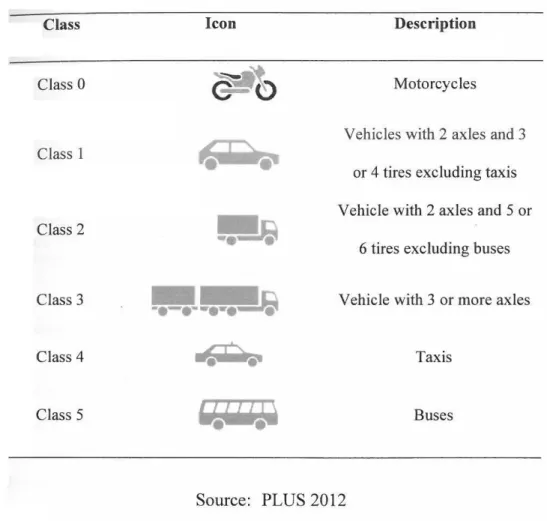
establishment is to impose and collect tolls from motorists (Malaysian Highway Authority 2010). Motorists are tolled according to their vehicle class and distance of their travel using the highway. There are six classes of vehicles that were defined as shown in Table 2.1. Class 1, class 2 and class 3 are differentiated by their number of axles and tires. Motorcycles are class 0, taxis are class 4 and busses are class 5. However, motorcycles are exempted from toll fare. Meanwhile, busses and taxis have no difference in term of their number of axle and tires to class 1 and class 2 but they are differentiated by their services.
8
TABLE 2.1 Vehicle classes in Malaysia
Class Icon Description
Class 0
G:IO
MotorcyclesVehicles with 2 axles and 3 Class 1
or 4 tires excluding taxis
-
Vehicle with 2 axles and 5 orClass 2
6 tires excluding buses
Class 3
w~
Vehicle with 3 or more axlesClass 4 ~ Taxis
·=
••
Class 5
"'•'I
'.Q
BusesSource: PLUS 2012
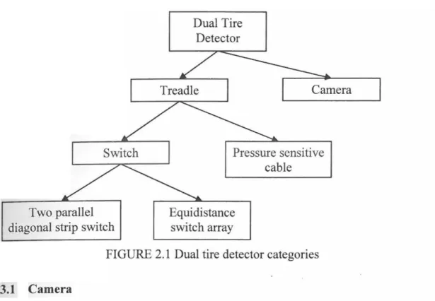
2.3 DUAL TIRE DETECTOR TECHNOLOGY
Every dual tire detector (DTD) has the ability to indicate tire tread width. An
overview of DTDs' categories is shown in Figure 2.1. The DTD can be categorized into two types which are treadle and camera. Meanwhile, the treadle can be divided
into switch treadle and pressure sensitive cable treadle. The switch treadle can be
further branched out to two parallel diagonal strip switch and equidistance switch
array. Therefore, the DTD has four major models as follow:
1. Equidistance switch array
11. Two parallel diagonal strip switch
iii. Pressure sensitive cable iv. Camera
Switch
Two parallel diagonal strip switch
Dual Tire Detector
Pressure sensitive
cable
Equidistance switch array
FIGURE 2.1 Dual tire detector categories 2.3.1 Camera
9
One of the methods to estimate tire width is through image processing. The method is
done by firstly photographing the image of the vehicle rear side. Then, a tire region detection unit will scan through the binary coded image to find a half elliptical shape in the lowermost region. The tire shape is verified by template matching algorithm and the vehicle width is determined. Then, tire width is measured with reference to the vehicle width (Lim 2005).
Estimating tire width with image processing acquires complex algorithm and
computation. Furthermore, the accuracy is very dependent on weather and lighting condition. In good condition the accuracy achieved for tire detection is only 78 %
which is not satisfactory to the toll industry (Achler & Trivedi 2004). However, camera technology is developing rapidly by embracing alternative imaging devices
such as infrared camera and scanning laser sensor (Hussain & Moussa 2005). One of
the advantage of this DTD is the installation does not disrupt traffic flow.
10
2.3.2 Treadle
Treadles are the sensors that are embedded in the road surface. This type of dual tire technology is one of the most commonly used for automatic vehicle classification since the toll industry started. It can classify vehicle at high accuracy rate but faces the challenge of robustness and durability. There are two types of treadle namely switch type treadle and pressure sensitive treadle. Meanwhile the switch type treadle can be
branched out to equidistance switch array and two parallel diagonal strip switches.
a. Switch Type Treadle
There are two types of switch treadle which are equidistance switch array and double parallel diagonal strip switch that will be discussed in the next section. Both DTDs use
switch concept to indicate tire width. The treadle switch concept is the same as push-to-make switch concept. The individual switch will be actuated when pressed and go
back to its normal form when the treading force has been removed.
Nagel's (1950) switch design is fully made out of metal and steel. However,
components that are held together by nuts and bolts are easily damaged by constant vibration and deformation. The treadle packaging later included elastomeric material.
This elastomeric material is used not only to protect the switches from direct contact of vehicles but also used as the mechanism to elate the switch after being pressed (Goble 1967). Example of treadle switch contained in elastomeric material is shown in
Figure 2.2. In fact, both designs took the advantage of the material rigidity to return
switch to its open circuit form after it was depressed.
Elastomeric
material
CROSS CUTT
.... 2
All measurements are in millimeter
T
FIGURE 2.2 Example of treadle switch (cross section view)