ELECTROLYSIS PROPULSION FOR SMALL-SCALE SPACECRAFT
A Dissertation
Presented to the Faculty of the Graduate School of Cornell University
In Partial Fulfillment of the Requirements for the Degree of Doctor of Philosophy
by
Rodrigo A. Zeledon May 2015
ELECTROLYSIS PROPULSION FOR SMALL-SCALE SPACECRAFT
Rodrigo A. Zeledon, Ph. D. Cornell University 2015
In the past decade, CubeSats have revolutionized small spacecraft missions. These miniature satellites began as educational projects but have lowered the bar for access to space and enabled research institutions and companies to launch technology demonstration and science missions in low Earth orbit. Propulsion systems small enough to fit in a CubeSat can extend the benefits of CubeSats beyond low Earth orbit, and potentially even allow for small-scale interplanetary missions. Propulsion systems designed for CubeSats must overcome severe restrictions in their chemistry, dimensions, mass and operation scheme for the sake of fitting within the CubeSat deployer and conforming to CubeSat specifications.
This research presents a novel concept for small satellite propulsion based on the electrolysis of water. These systems are designed to ensure the safety of the launch vehicle and overcome the restrictions imposed by operating as a secondary payload by avoiding the use of hazardous materials, pressure vessels and explosives. Numerical analyses are used to predict the performance of the propulsion system. Vacuum chamber experiments on a prototype of the propulsion system are conducted to determine the performance of the system.
An analysis of the attitude dynamics and operation of a satellite with an electrolysis propulsion system are presented. The propulsion system as well as the attitude control of the spacecraft are aided by the spacecraft’s spin about its major axis
of inertia. Energy damped by the water carried on board keeps the satellite stable and damps nutation caused by external torques and the use of the propulsion system.
Several applications are presented for low earth orbit as well as interplanetary CubeSats. The design of a mission to navigate a CubeSat to lunar orbit as part of NASA’s CubeQuest Challenge is detailed. Prospects for broader applications of this work involving distributed exploration using in-situ water are identified.
BIOGRAPHICAL SKETCH
Rodrigo Zeledon grew up in San José, Costa Rica and completed his high school education at Country Day School in Escazú in 2005. He then attended the Massachusetts Institute of Technology where he obtained the degree of Bachelor of Science in Aerospace Engineering in June of 2009. He moved to Ithaca, NY in 2009 to pursue his graduate studies at Cornell. There he joined Dr. Mason Peck’s Space Systems Design Studio, initially working on steering laws for control moment gyroscopes before focusing on electrolysis propulsion systems.
ACKNOWLEDGMENTS
I would like to thank my advisor, Dr. Mason Peck, for all his help and guidance. Mason, your advice and enthusiasm for my work have been a continued source of motivation. Your passion for your work and for the field has been a great example in my graduate studies. I would also like to thank the members of my committee, Dr. Mark Campbell and Dr. Peter Gierasch, for their guidance and perspective. I would like to specifically mention Dr. Ephrahim Garcia, who was the fourth member of my committee, for his help and advice during the most difficult parts of my time at Cornell, and for his encouragement in the form of repeated shouts of “why haven’t you graduated already?”
I would like to thank my parents and grandparents, who early on cultivated in me a sense of curiosity and of the importance of being ethical. They have always been there for me when I needed advice, encouragement, a fresh perspective, or simply a rum and coke. Their love and support have been constant throughout my life, and for that I cannot thank them enough. My sister, Mariela, has always been an inspiration and a role model. Beginning in grade school, she has always set an extremely high bar for me.
I would like to give thanks to the alumni, staff and current students of the Space Systems Design Studio. Laura, thanks for the encouragement and help as we toiled on CMG papers, and for all your help in the job search! Justin, Joe, and Mike, thanks for setting a great example. Liran, Zac, Ben, and Lorraine, thanks for the insightful chats, discussions and help throughout these years. Ryan, other Ryan, Kyle, Frankie and Hunter, best of luck in the journey ahead, you guys are a great team!
To the MAE staff, especially Marcia and Patti, thanks for being a beacon in the bureaucratic fog that Cornell can sometimes be. Your ability to keep things running
smoothly amazes all of us.
To all of the undergraduate and M.Eng students who worked on my project, I cannot thank you enough. Your hard work has been absolutely crucial to the project, and I’m extremely thankful for having the opportunity to work with such talented people.
To the amazing friends I made in Ithaca, and to old friends who have encouraged me throughout these years, I really could not have made it without you. I will miss all of the fun times in Ithaca, and look forward to hearing about the amazing things you are all doing.
Finally, I would like to thank the organizations that have provided funding for me and for my project. Without their generous support, none of this would have been possible. I would like to thank the Alfred P. Sloan foundation, the National Action Council for Minorities in Engineering and Cornell Diversity Programs in Engineering for awarding me a Sloan grant. I would also like to thank Moog, Inc. for providing funding, advice and engineering support for the project, as well as Northrop Grumman, New York NASA Space Grant, and NASA/JPL for their support.
TABLE OF CONTENTS Biographical Sketch ... v Dedication ... vi Acknowledgements ... vii Table of Contents ... ix List of Figures ... x List of Abbreviations ... xi
List of Symbols ... xii
Chapter 1: Introduction ... 1
Chapter 2: Design and Testing of Electrolysis Propulsion Systems ... 7
Chapter 3: Attitude Dynamics and Control ... 25
Chapter 4: Applications and Mission Architectures ... 48
Chapter 5: Conclusion ... 54
References ... 57
Appendix: Generalized Framework for Linearly Constrained Control Moment Gyro Steering ... 61
LIST OF FIGURES
Figure 1. Schematic of the operation of an electrolysis propulsion system. ... 8
Figure 2. Two alternate valve arrangements downstream of the water tank. ... 8
Figure 3. Electrical power available to a CubeSat in an example GTO orbit. ... 11
Figure 4. Pressure in the combustion chamber during a test firing. ... 13
Figure 5. ANSYS/Fluent simulation of fluid flow through the nozzle. ... 16
Figure 6. Prototype with combustion chamber and nozzle as a single block. ... 17
Figure 7. Cutaway of prototype electrolysis propulsion system. ... 20
Figure 8. Prototype electrolysis propulsion system. ... 21
Figure 9. Chamber pressure vs. Specific impulse at low pressure. ... 23
Figure 10. Chamber pressure vs. Impulse. ... 24
Figure 11. Simulation of satellite de-spin maneuver using magnetorquers. ... 37
Figure 12. Distribution of final angular velocity of the satellite about each principal axis for 100 runs. ... 38
Figure 13. Gravity Gradient Torque for One Orbit. ... 43
Figure 14. Solar torque acting on the rotating spacecraft. ... 45
Figure 15. Approximate location of the centers of mass and center of pressure for the Lunar CubeSat. ... 45
Figure 16. Solar torque about z-axis in Lunar CubeSat for two rotations. ... 46
Figure 17. Orbit profile starting from an SLS deployment. ... 50
Figure 18. The Cornell Lunar CubeSat. ... 53
Appendix Fig. 1 Scissored Pair of CMGs. ... 75
Fig. 2 Arrangement of Three Orthogonal Scissored Pairs. ... 75
Fig. 3 Planar representation of CMG momentum in a zero-momentum state. ... 79
Fig. 4 Internal singularity for triplet arrangement. ... 79
Fig. 5 Triplet CMGs in a trapezoid configuration. ... 80
Fig. 6 Two Triplets of CMGs at Right Angles. ... 84
Fig. 7 Momentum envelope for two orthogonal triplets. ... 84
Fig. 8 Log minimum determinant of the normalizedJ( ) ( ) J Tvs. total slew angle. 87 Fig. 9 Log maximum torque normalized error vs. total slew angle. ... 88
Fig. 10 Example slew. ... 89
Fig. 11 Example slew torque ... 90
Fig. 12 Example slew CMG gimbal angles, rates and accelerations ... 92
LIST OF ABBREVIATIONS
P-POD Poly-PicoSatellite Orbital Deployer
U CubeSat Unit, approximately a 10 cm x 10 cm x 10 cm volume LEO Low Earth Orbit
ACS Attitude Control System GEO Geostationary Earth Orbit GTO Geostationary Transfer Orbit
NASA National Aeronautics and Space Administration SLS Space Launch System
EM-1 Exploration Mission 1 AU Astronomical Unit
PEM Polymer Electrolyte Membrane STP Standard Temperature and Pressure CM Center of Mass
CAD Computer Aided Design
PD Proportional-Derivative control
IGRF International Geomagnetic Reference Field TLE Two-Line Element
NORAD North American Aerospace Defense Command GPS Global Positioning System
CMOS Complementary metal–oxide–semiconductor RAM Random-Access Memory
LIST OF SYMBOLS ΔV change in orbital velocity, m/s
𝑛𝐻2 moles of hydrogen gas, mol 𝑃𝑒𝑙𝑒𝑐 electrical power, W
𝑡 time, s
𝜂 electrolyzer efficiency
𝐻𝑓 heat of formation, J/mol
𝑉𝑡𝑎𝑛𝑘 total tank volume, m3
𝑝 pressure, Pa
𝑅 universal gas constant, J/(mol K)
𝑇 temperature, K
𝑉𝑔𝑎𝑠 volume of electrolyzed gas, m3 𝛾 specific heat ratio
𝑀 molar mass, kg/mol
𝑣 fluid velocity, m/s
𝐴 cross-sectional area, m2
𝐹 thrust, N
𝑚̇ mass flow rate of propellant, kg/s
𝑔0 acceleration due to gravity at the earth’s surface, m/s2 𝐼𝑠𝑝 specific impulse, s Δ𝑚 change in mass, kg 𝐼 impulse, N s 𝑚𝑝𝑟𝑜𝑝 propellant mass, kg 𝑚𝑠𝑎𝑡 satellite mass, kg 𝐵𝑜 Bond number ∆𝜌 density difference, kg/m3 𝑎 acceleration, m/s2 𝜎 surface tension, N/m L characteristic length, m
𝝎 spacecraft angular velocity, rad/s
r distance between fluid’s free surface and spacecraft center of mass, m
I spacecraft inertia dyadic, kg m2
H spacecraft angular momentum vector, Nms
τ torque acting on spacecraft, Nm
𝜃 precession angle, rad
𝝉𝑀 torque produced by magnetorquers, Nm
𝑴 magnetic moment, Am2
𝑩 magnetic field, T
𝑅𝐸 Earth radius, m
𝐵0 magnitude of Earth’s magnetic field, T
𝜑 total reorientation angle, rad
𝜇 Earth geopotential, m3/s2
𝝉𝐺𝐺 gravity gradient torque, Nm
rsat position of spacecraft center of mass relative to Earth’s center, m 𝜈 true anomaly, rad
𝝉𝑆 torque due to solar pressure, Nm
𝐹𝑆𝐶 solar illumination constant, W/m2
𝑐 speed of light, m/s
𝐶𝐴 absorption coefficient
𝐴 illuminated cross-sectional area, m2
𝑑 solar torque moment arm, m
𝒔̂ sun direction vector
𝒏̂ surface normal vector
𝒙
CHAPTER 1 INTRODUCTION
Propulsion systems for CubeSats have been of interest to the CubeSat community ever since the inception of the CubeSat standard [1]. As the development of other technologies critical to the use of CubeSats in interplanetary missions has progressed, technology development for propulsion systems has taken on even greater urgency [2]. The deployment methods used for CubeSats today include deployment as secondary payloads or deployment from the International Space Station. Both of these methods, however, impose strict limitations to candidate propulsion systems at this scale [3]. The technology challenge is not merely the reduction of existing large-scale propulsion into an envelope small enough to fit in one of these satellites. Rather, the main limitations have to do with safety, both for the primary payload and for those tasked with handling and integrating the CubeSat onto the rocket [4]. Most large-scale propulsion schemes make use of explosive and reactive chemicals, materials stored either cryogenically or at high pressures, or propellants that are toxic and require special handling. While a technology-demonstration system employing one of these schemes could fly on a CubeSat provided the proper waivers are obtained, the risk and paperwork involved make it unlikely that such a propulsion system could gain acceptance as a system to be used regularly on many CubeSat missions.
Large-scale electrolysis propulsion systems were first proposed by Stechman and Campbell in 1973 as a means of providing primary propulsion and attitude control for large satellites [5]. These concepts were advanced by Stedman in 1976 by
introducing the regenerative fuel cell [6]. The regenerative fuel cell made it possible to use the system as a battery since it provides energy storage in the form of chemical energy [7]. The process can then be reversed to provide electric power when needed [8]. This system could also be used to provide drinking water and oxygen to the crew, albeit at the expense of the storage and propulsive capabilities of the system [9]. The operational flexibility of the system came at the expense of storage volume and mass. In order to use the fuel cells to generate electricity, the hydrogen and oxygen gases need to be separated during the electrolysis process and then stored in separate tanks [10]. This scheme makes the system bulky and complex, which prevented its acceptance on flight programs. These large-scale concepts were revisited in the 1990’s by de Groot et. al. and their merits as integrated power and propulsion modules for small spacecraft were also examined [11] [12]. However, the complexity of the regenerative system limits its applications.
CubeSats have existed since 2000 [13] and in the past decade and a half have transformed from educational projects to tools for much broader research and technology demonstration missions. Conforming to CubeSat standards has two main benefits [14]. First, it allows for ready integration with the launch vehicle by specifying agreed-to dimensions and mass properties of the CubeSats. The launch vehicle only needs to incorporate a standard deployer, either the P-POD or its 6U version [15], inside of which any CubeSat that adheres to the standards can be integrated. Second, the standardized sizes allow for the use of off-the-shelf components. This feature permits the CubeSat designer to focus on the payload or on the experimental components, reducing the cost and time necessary to develop custom
components for every subsystem. In these two ways, CubeSats lower the bar for access to space by reducing the cost and complexity associated with larger spacecraft.
So far, all CubeSats have operated in low Earth orbits determined by the deployment from the launch vehicle. However, none have incorporated propulsion capable of substantial ΔV. In order to extend the operational envelope of CubeSats beyond Low Earth Orbit (LEO), or to provide CubeSats with a means of significantly changing their orbits, a propulsion system beyond the current state of the art is required. Such a propulsion system should also be consistent with the general philosophy of CubeSats, providing the required performance at a low cost and under strict power, mass and volume limitations.
The development of a propulsion system for CubeSats (or other secondary payloads) involves accommodating restrictions not only in mass and volume, but also restrictions in the use of hazardous propellants, launch-vehicle safety, use of pressure vessels, power consumption, and cost, to name a few. Electrolysis propulsion systems fit well within these constraints and represent a viable option for high ΔV propulsion at the CubeSat scale. An electrolysis propulsion system uses only water as propellant, is unpressurized and safe during launch, can operate in very low power modes, and leads to a relatively inexpensive system.
This dissertation highlights several contributions made in the field of small spacecraft propulsion systems and dynamics. The concept and architecture for an electrolysis propulsion system for small spacecraft is presented. The test equipment and experimental setup required for testing the performance of the system is described and results from early performance tests are presented.
Demonstration missions are an important part of technology development. Another contribution, with the aim of supporting a future demonstration mission, is the evaluation of system architectures for two possible demonstration missions. These case studies highlight the utility of electrolysis propulsion systems in missions beyond LEO, and missions where impulsive V is desired.
The final contribution is the use of the satellite’s passive dynamics to simplify the design of the propulsion system and reduce the number of required attitude control system (ACS) actuators. The energy dissipation from the fluid slosh in the water tank contributes to restoring a major axis spin, which is the lowest energy state for the spacecraft. This fact allows for a design of an attitude control system that requires only a single cold gas thruster to control the direction, but not the magnitude, of the angular momentum. This in turn means that the direction about which the spacecraft is spinning can be controlled, but the phase of the spin or the spin rate cannot be controlled by the cold gas thruster. This control system vastly reduces the number of required actuators, and as an added benefit, the satellite spin also provides passive gyroscopic stiffness in the presence of external torques.
The architecture proposed here takes advantage of the small size and limited mass of the 3U CubeSat bus to motivate the design of a propulsion system that, while similar in the fundamental operation to large electrolysis systems, affords several key benefits that make it especially suitable at the CubeSat scale or for use on secondary payloads. These benefits could allow electrolysis propulsion systems to operate safely as secondary payloads and provide primary propulsion for CubeSats in Low Earth
Orbit, or even interplanetary CubeSats on their way to the moon, asteroids and beyond.
The system works by converting solar energy into chemical energy, which can be used to propel the spacecraft. The electricity generated by the solar cells is used to electrolyze liquid water into hydrogen and oxygen gas. Effectively, the propellant itself serves as a battery, storing the electrical power with far greater mass efficiency and none of the electrical losses associated with batteries. The mass savings due to eliminating batteries for the propulsion system and replacing that mass with propellant is a striking benefit of this architecture. Each of the electrolyzers operates at 2V and uses 2W of power. Several electrolyzers are used in parallel, so that the number of electrolyzers that are operational at any point determines the power devoted to electrolysis. This allows the propulsion system to be flexible in its power use, accommodating other subsystems or payloads that might also require some of the limited power available on the CubeSat. This design can potentially eliminate the need for deployable solar panels that are a requirement for many other electric propulsion options at the CubeSat scale.
The tank pressure rises as water is electrolyzed into hydrogen and oxygen. This gas is kept as a mixture, not separated into hydrogen and oxygen tanks. When the gas pressure is sufficiently high and a burn is desired, a solenoid valve opens to allow gas to flow into a combustion chamber. The flight computer then activates a miniature spark plug that ignites the gas mixture. The combustion products then expand through a small nozzle located near the spin axis, generating thrust.
The spacecraft spins in order to separate the water from the oxygen and hydrogen mixture in the fuel tank, ensuring that the valve leading to the combustion chamber always ingests gas, not water. This spin axis is designed to lie as close as possible to the thrust axis. The spin is established after spacecraft separation from the CubeSat deployer. This spin can be achieved by magnetic torquers embedded in the solar panels or by deploying a reaction mass. The spin rate must be high enough to both effectively separate the water from the electrolyzed gases and provide gyroscopic stability in the presence of disturbance torques. Therefore, the spacecraft cannot actuate the spin via reaction wheels, as this would lead to a non-stiff, zero-momentum spacecraft. The attitude dynamics of the spacecraft, including simplified reorientation schemes made possible by the use of a spinning satellite, is one of the focus areas of this work.
Possible applications of this technology include Low Earth Orbit lifetime extension, orbit change maneuvers, and main propulsion for interplanetary missions. A concept for such a mission is analyzed, beginning with deployment on a lunar insertion orbit or lunar flyby. This mission is designed to be compatible with NASA’s CubeQuest centennial challenge, which would include a 6U slot on the first launch of the Space Launch System (SLS), EM-1. This concept may also have broader impacts, particularly in the use of in-situ water to extend the use of the propulsion system to Earth return without the need to transport propellant from Earth. These prospects are identified but left for future work.
CHAPTER 2
DESIGN AND TESTING OF ELECTROLYSIS PROPULSION SYSTEMS
Basic Operation
The electrolysis propulsion system is composed of a liquid water tank with embedded electrolyzers, a combustion chamber and a nozzle. At launch, the liquid water tank is at atmospheric pressure and therefore the system is inert. The electrolyzers are powered by electricity from solar panels, supplied through the satellite’s power distribution system. Several arrangements of valves are possible downstream of the liquid water tank. In the baseline architecture, the water tank is isolated from the combustion chamber by a solenoid valve, which is normally closed and can be opened through a signal from the flight computer, and a passive check valve. A second check valve between the combustion chamber and the nozzle prevents any gas from escaping before the explosion. The second arrangement of valves sacrifices some performance and simplifies the operation by removing the check valve between the combustion chamber and nozzle. The third arrangement involves only passive check valves. This arrangement requires careful selection of the cracking pressures, but would not require any actively-controlled valves.
In any of these three arrangements the amount of gas generated cannot sustain continuous combustion and propulsion. The combustion chamber contains a miniature spark plug, which ignites the gas in a controlled explosion in the combustion chamber. The general operating scheme is shown in Figure 1, and the two alternate valve arrangements are shown in Figure 2.
A.Electrolysis
The first step in the operation of the propulsion system is the electrolysis of the liquid water. The distilled water is broken down into gaseous hydrogen and oxygen by electrolyzers which are mounted on the inside of the water tank. Other electrolysis
Figure 1. Schematic of the operation of an electrolysis propulsion system.
concepts, including those proposed for large spacecraft and primary launch vehicles, store the gases separately in two tanks. These larger systems include dryers and various mechanisms and pumps to ensure that no cross contamination occurs. The propulsion systems then use the separate gases stored at high pressure or as liquids in a conventional injector-type combustion chamber [5]. The electrolysis propulsion system for CubeSats operates with pre-mixed hydrogen and oxygen as a single gas—a stoichiometric ratio of H2 and O2—and therefore the gases are stored together in the
liquid water tank. This architecture reduces the complexity, mass and size of the system at the expense of not being able to use the stored hydrogen and oxygen to generate electricity through a regenerative fuel cell.
The energy required to separate the liquid water into hydrogen and oxygen gas is the heat of formation of water multiplied by the efficiency of the electrolyzer, along with some minor losses. The heat of formation here is the energy required to break down one mole of water into one mole of hydrogen gas and half a mole of oxygen gas. For every gram of water electrolyzed, the spacecraft must generate at least 15.86 kJ, which at a power of 6 W would take the spacecraft 0.73 hours. The amount of hydrogen produced is given by dividing the energy supplied to the electrolyzers by the heat of formation, then multiplying by 𝜂, the efficiency of the electrolyzers in converting electrical energy into chemical energy:
𝑛𝐻2 = 𝑃𝑒𝑙𝑒𝑐𝑡𝜂
𝐻𝑓 ( 1 )
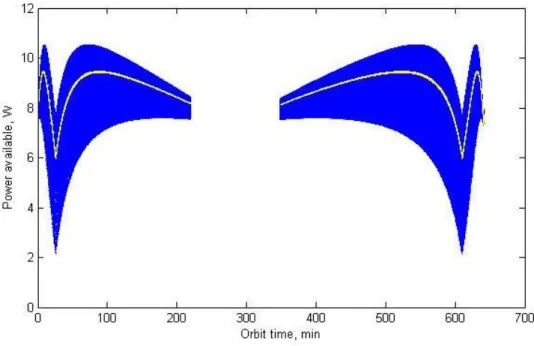
A typical 3U spacecraft at 1 AU from the Sun can generate anywhere between 2 and 10 W using only body-mounted solar panels, depending on its orientation. The
power profile for a 3U spacecraft in a Geostationary Transfer Orbit (GTO) is shown in Figure 3. The 3U spacecraft contains three electrolyzers, each operating at 2W. This allows the system to operate at 2, 4 or 6W, depending on the available power, spacecraft operating mode and power consumption of other subsystems. As these electrolyzers break down the water into H2 and O2 gas, the pressure in the chamber
increases. In the case of the design tested as part of this work, the initial pressure in the tank before the electrolysis process begins is 1 atm, which could be established prior to sealing the tank with either hydrogen, oxygen, air, or a mixture of hydrogen and oxygen. If we make the likely assumption that a stoichiometric mixture of hydrogen and oxygen results from the electrolysis, the entire volume of gas after electrolyzing will be hydrogen and oxygen in a stoichiometric ratio, and the fractions will not vary with the cycle number. The total volume of the tank (Vtank) is approximately 0.8 L for
the 3U spacecraft studied in depth here. The volume of gas before operation, and therefore the initial fill fraction, is a parameter to be chosen based on the mission’s required ΔV profile. The electrolyzers generate gas at a rate that is dependent on the power used and the efficiency of the electrolyzers.
Since the electrolysis reaction produces one mole of H2 and half a mole of O2
for every mole of H2O, the number of moles of gas produced by the reaction is 3
2𝑛𝐻2 for every mole of H2O. From the ideal gas law, the pressure inside the tank is 𝑝 = 3𝑃𝑒𝑙𝑒𝑐𝑡𝜂𝑅𝑇
2𝐻𝑓𝑉𝑔𝑎𝑠
( 2 )
If the initial ullage volume is very small, then 𝑉𝑔𝑎𝑠 is proportionately small at the beginning of the mission. Therefore, the pressure increases very rapidly when the electrolyzers are powered, but only a small mass of water will have been electrolyzed. Therefore, the pressure in the tank decreases significantly after a firing, and the system can fire only a few times before it must electrolyze to build up the pressure. If the initial ullage volume is large, the system takes a longer time to recharge but can
Figure 3. Electrical power available to a CubeSat in an example GTO orbit. The blue line shows the power for a rotating 3U CubeSat using body-mounted solar panels. The yellow line shows the power averaged to remove the effects of spacecraft rotation.
provide more ΔV at the beginning of the mission. For missions that require a quick burst of ΔV at the start, this ullage can be a benefit. The ability to provide larger ΔV at the beginning of the mission, however, comes at the expense of the total mission ΔV because the tank begins at a lower fill fraction.
The efficiency of the electrolyzers can be characterized by measuring the power into the electrolyzers and the amount of gas generated. Rearranging Equation 2 to solve for the efficiency,
𝜂 = 𝑛𝐻2𝐻𝑓 𝑃𝑒𝑙𝑒𝑐𝑡
( 3 )
The numerator of Equation 3 can be determined via the ideal gas law by measuring the volume and pressure of the gas generated in time t at a controlled temperature T. Equation 3 then becomes
𝜂 = 𝑝𝑉𝐻𝑓 𝑅𝑇𝑃𝑒𝑙𝑒𝑐𝑡
( 4 )
The electrolyzers were tested to determine their efficiency and compared against alkaline electrolyzers operating with potassium hydroxide solutions. The KOH electrolyzers have maximum efficiencies of 72% +/- 4%. The PEM electrolyzers have a greater efficiency, measured to be 92% +/- 4% [16].
B.Combustion
Once the pressure in the tank is high enough for a firing, the flight computer activates the solenoid valve downstream of the water tank. Because of the satellite’s rotation, only gas is ingested into the manifold that connects the tank to the combustion chamber [17]. The pressure of the gas needs to be high enough to open the
check valve that is downstream of the solenoid valve. This valve serves to protect the solenoid valve from the explosions that happen in the combustion chamber, and can have a very low cracking pressure, usually on the order of a few psi. Typical off-the-shelf check valves for this application can withstand a back pressure up to 5000 psi, whereas the commercially-available solenoid vales that are small enough for the system typically have maximum pressures of at most 1000 psi. The functionality of the check valve and solenoid valve could be condensed into a single solenoid valve that can withstand back pressures above the combustion pressure, but these valves are either too large or not commercially-available. While the operating pressure can be chosen to some extent, the combustion and expansion processes are more efficient at higher pressures.
The solenoid valve needs to open long enough that the pressure reaches equilibrium in the combustion chamber. In practice this happens within 0.5 s of the valve opening for operating pressures approximately 50 psi to 100 psi. The valve is
then closed to conserve power. The gas is kept from escaping the combustion chamber by the second check valve. This valve is downstream of the combustion chamber, before the nozzle. The cracking pressure of this valve needs to be greater than the difference between the operating pressure of the water tank and the cracking pressure of the first check valve. While some margin should be used, a cracking pressure that is too high sacrifices performance. This sequence of events is shown in Figure 4 for a test firing in the vacuum chamber.
Once the solenoid valve is closed, the chamber is armed for firing. This firing does not need to take place immediately, but enough margin should be allowed for the valves to close completely. Combustion is initiated only when enough activation energy is applied to the hydrogen/oxygen mixture [18]. This energy comes from a spark plug embedded in the chamber. The spark plug is also an off-the-shelf part and is powered by a 5V line through a simple capacitive charging circuit. The command to activate the spark plug comes from the flight computer as well.
Combustion in the chamber increases the pressure and temperature of the gas enough that the check valve between the chamber and nozzle is opened. The laminar speed of the flame at the operating temperature and pressure is approximately 20 m/s [19] so the flame should propagate through the chamber in at most 2.4 ms, or about 1% of the duration of a pulse. The gas is then expanded by the nozzle, generating thrust. Because the mixture of hydrogen and oxygen is stoichiometric, the resulting product of combustion is almost exclusively steam.
C.Theoretical performance
A numerical model to estimate the performance of the engine was implemented in MATLAB. This model was then also implemented in ANSYS/Fluent in order to verify the performance characteristics. Combustion is assumed to occur at a much faster scale than the speed of sound and therefore faster than the fluid flows out of the nozzle. For this reason, the gas can be assumed to combust in a fixed volume. The temperature of the gas after combustion is therefore given by the change in enthalpy of the gas, and the pressure is given by the ideal gas law [20].
∫ 𝐶𝑝(𝑇)𝑑𝑇 = ∑ 𝑛𝑝ℎ𝑝(𝑇𝑓) 𝑝 − ∑ 𝑛𝑟ℎ𝑟(𝑇0) 𝑟 𝑇𝑓 𝑇0 ( 5 )
The reactants in Equation 5 above are the hydrogen and oxygen gas, which are assumed to be at STP, while the products are assumed to be mainly water vapor at the final combustion temperature. This gas is then expanded to vacuum through a parabolic nozzle. The conditions at the chamber are taken to be the stagnation conditions and the flow is assumed to be isentropic, such that the following relation holds
𝑇𝑥⁄𝑇𝑥 = (𝑝𝑥⁄𝑝𝑦)
(𝛾−1) 𝛾⁄ ( 6 )
The velocity at any axial position along the nozzle is a function of the pressure at that position and the stagnation temperature, and is given by [21]
𝑣𝑥 = √ 2𝛾 𝛾 − 1 𝑅𝑇1 𝑀 [1 − ( 𝑝𝑥 𝑝1 ) (𝛾−1) 𝛾⁄ ] ( 7 )
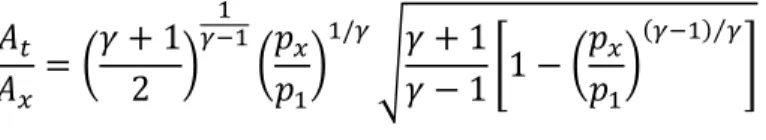
The pressure at any axial position along the nozzle is in turn a function of the area ratio, and is given by [21]
𝐴𝑡 𝐴𝑥 = ( 𝛾 + 1 2 ) 1 𝛾−1 (𝑝𝑥 𝑝1) 1/𝛾 √𝛾 + 1 𝛾 − 1[1 − ( 𝑝𝑥 𝑝1) (𝛾−1) 𝛾⁄ ] ( 8 )
These equations can be solved numerically in an iterative approach that takes into account the varying initial conditions in the throat and the temperature dependence of the specific heat ratio. This analysis results in an average velocity at the nozzle exit of 3068 m/s. This exit velocity implies a specific impulse of 313 s. In practice, the specific impulse can be expected to be comparable but somewhat lower because of losses in the check valve, surface roughness in the nozzle and heat loss through conduction to the walls.
A similar analysis using ANSYS/Fluent provides an estimate of average specific impulse of 366 s. This model uses the initial conditions generated by the MATLAB model as quasi-static time-varying boundary conditions The velocity profile for this simulation is shown in Figure 5.
Figure 5. ANSYS/Fluent simulation of fluid flow through the nozzle.
Alternative configurations
The baseline configuration involves an actuated valve and two passive check valves. However, several other valve arrangements are also possible that can offer simplified performance at the expense of specific impulse or thrust.
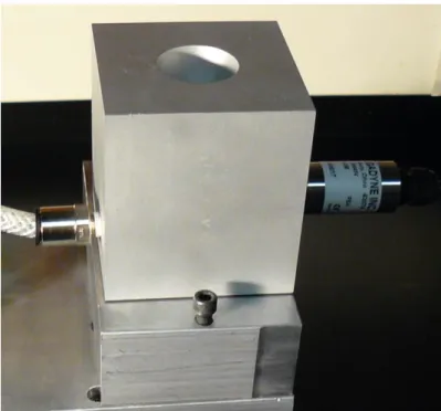
Simplified operation can be achieved by foregoing the check valve between the combustion chamber and the nozzle. This valve prevents gas from escaping before the spark plug is fired, but with a small enough throat diameter, the amount of gas that escapes is small. The nozzle and chamber could be constructed as a single piece. The diameter of the throat becomes a parameter that balances what is necessary for an optimal nozzle expansion and the rate of escape of the gas before the spark plug is fired. When the solenoid valve is opened, the pressure in the combustion chamber increases until the solenoid is closed. At that point, pressure decreases. Ideally, the spark plug would ignite the gas immediately after the solenoid closes, but in practice a
Figure 6. Prototype with combustion chamber and nozzle as a single block.
small amount of time is needed so that the valve can fully close. This timing can be optimized in order to maximize the pressure, and therefore the thrust, generated by the engine.
The second alternative scheme is a system that uses only passive check valves, therefore reducing the complexity of the system. The only controls of the system would be the power to the electrolyzers and the spark plug. Because there is no actuated valve, the system must include a check valve before the nozzle to prevent the gases from escaping. The cracking pressure of these check valves must be carefully selected so that the system operates at the required pressure. The check valve between the water tank and the combustion chamber is set at a cracking pressure 𝑝1. The check valve between the combustion chamber and the nozzle is set at a cracking pressure 𝑝2. 𝑝2 should be slightly larger than 𝑝1, so that no gas escapes before the mixture is ignited. If the cracking pressure 𝑝2 is much larger than 𝑝1, the valve causes a large drop in pressure and the engine’s efficiency decreases.
This second configuration can also include a method of recapturing water vapor after each firing and delivering it back to the water tank. Otherwise, a significant amount of water vapor in the combustion chamber can hinder the ignition of the hydrogen/oxygen mixture. The recapture of water vapor can be accomplished via absorbent walls, or thin capillaries in the combustion chamber that allow water to flow back into the tank. A method of recapturing water has not yet been designed and would be required before this scheme can be tested or implemented.
Performance tests
The goal of performance tests is to attain values of specific impulse, thrust and chamber pressure that can be used to analyze the system, optimize it, and provide performance parameters for implementation in missions. These tests are necessary before a final flight version of the propulsion system can be designed, as the size and mass of many of the components depends on the values attained during testing.
A.Equipment
The prototype system developed at Cornell University’s Space Systems Design Studio has approximately the same internal dimensions that a 3U flight version would have, and it is designed for testing inside a vacuum chamber. Operation in Earth’s gravity simplifies the operation of the thruster because there is no need to spin the propulsion system to provide the acceleration field that achieves gas separation. Instead, the tank is mounted at a right angle from the thruster, in order for the gas to rise to the top of the tank. The thruster points up so that the force can be measured by load cells below the prototype. Dynamical testing of a mass mockup to verify the spin-actuated gas separation and the effect of fuel slosh will be done independently of the initial prototype propulsion system.
The components of the brassboard prototype are analogous to the components of the flight version described in the Basic Operation section. A single tank stores the liquid water propellant and electrolyzed gases. Three electrolyzers are installed inside the tank. Electrical power is supplied to the electrolyzers from an external power supply, through a feedthrough installed in the tank. A pressure transducer monitors the
internal pressure of the tank to indicate when the pressure is high enough for a firing to occur.
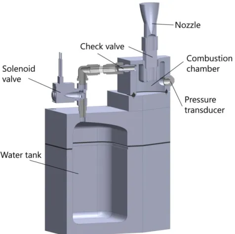
Gas is allowed to flow into the combustion chamber when the pressure is sufficiently high, above 0.7 MPa for the test prototype. A solenoid valve controls the flow of gas into the combustion chamber. Gas is prevented from escaping the combustion chamber by a check valve between the chamber and the nozzle. A miniature spark plug ignites the hydrogen and oxygen mixture inside the combustion chamber once the signal for firing is given by the flight computer. A microcontroller sets the timing of the solenoid valve and the firing of the spark plug. The nozzle has the same internal dimensions as a flight nozzle but with thicker walls in order to provide a more rigid attachment with the combustion chamber. Figure 7 shows a
cutaway view of the prototype propulsion system, with the main components and sensors labeled.
The entire assembly is oriented such that the nozzle’s axis of symmetry is perpendicular to the ground and so that firing causes a downward force. Force measurements are taken by two strain gauges mounted on a plate upon which the prototype assembly is set. Measurements are taken at millisecond intervals and the data is recorded through a data acquisition card outside of the thermal vacuum chamber. Pressure inside the combustion chamber is also monitored through a pressure transducer. Figure 8shows the prototype and force measurement setup inside the thermal vacuum chamber.
Figure 8. Prototype electrolysis propulsion system on thrust measurement assembly in Cornell’s thermal vacuum chamber.
B. Measurements
Measurement of the power input for the electrolyzers is done by recording the voltage applied and current drawn throughout the electrolysis process. This allows for a measure of the amount of gas generated by the electrolyzers as given by Equation 1. The amount of gas in the chamber before a firing can be computed from the ideal gas law since pressure and temperature can be measured, the volume of the chamber is a known and fixed quantity, and the gases are assumed to be a stoichiometric mixture. The force data given by the strain gauges is integrated to compute the impulse in every pulse. The thrust generated by the engine and its specific impulse are related by
𝐹 = 𝑚̇𝑔0𝐼𝑠𝑝 ( 9 )
Equation 9 can be integrated to obtain the impulse on left hand side, as shown in Equation 10. The equation can then be rearranged to compute an average specific impulse for the pulse, as given in Equation 11.
∫ 𝐹 𝑑𝑡 = 𝑔0𝐼𝑠𝑝∫ 𝑚̇ 𝑑𝑡 ( 10 )
𝐼𝑠𝑝 = 𝐼 𝑔0∆𝑚
( 11 )
This measure of specific impulse is critical in sizing the water tank and, indirectly, the other components of the propulsion system for a given mission. The amount of fuel the spacecraft must carry is related to the total mission ΔV through the specific impulse, in the Tsiolkovsky rocket equation below.
∆𝑉 = 𝐼𝑠𝑝𝑔0ln (1 +𝑚𝑝𝑟𝑜𝑝
C.Test results
Experiments at reduced pressure, conducted inside the vacuum chamber, yielded performance values for two of the configurations described in the Basic Operation section of Chapter 2. The two configurations that have been tested are the baseline configuration using a solenoid and two check valves, and the first alternate configuration using a high pressure solenoid valve. Of these two, specific impulse measurements are only obtained for the baseline configuration, since the gas in the chamber can be readily measured. The results of these low pressure experiments are shown in Figure 9. The check valve after the combustion chamber was set at 65 psi to 85 psi during these firings, significantly above the chamber pressures that were measured. While no clear trend is apparent from this data, it is expected that both impulse and specific impulse will increase as the pressure in the chamber increases, especially when the chamber pressure is well-matched with the cracking pressure of the check valve.
Figure 10 shows the impulse from tests using both the alternate and the baseline configuration. The chamber pressure measurements for the alternate configuration are approximate, since the pressure in the chamber is transient and does not reach a stable value. This data shows that the impulse increases with the chamber pressure, although experiments at higher pressures will be necessary in order to reach the required performance for the system.
Figure 10. Chamber pressure vs. Impulse for the baseline and alternate configurations.
CHAPTER 3
ATTITUDE DYNAMICS AND CONTROL
The attitude dynamics necessary for the operation of the propulsion system seem to be complex and onerous at first glance. Spinning satellites, however, have a long history and are well-understood. Spinning while a thruster fires keeps the spacecraft from tumbling due to unwanted torques caused by misalignments. While these torques could be counteracted by the attitude control system, in CubeSats and other small spacecraft, a 3-axis attitude control system can be a large imposition. Such a system typically results in a significant fraction of the spacecraft devoted to reaction wheels or cold gas thrusters. Besides acting as the method of liquid-gas separation, by spinning the spacecraft significant reduction in the complexity of the system is achieved. This benefit is exemplified by the ability to reorient the spacecraft in any desired direction using only one cold gas thruster.
Satellite Dynamics and Attitude Requirements
A. Thrust axis spin rates for liquid-gas separation
A constant spin about the thrust axis separates the liquid water from the electrolyzed gases. This spin field obviates the need for the complex multi-tank storage systems proposed for large scale electrolysis propulsion systems and allows the CubeSat system to function with just one tank. The thrust axis spin can be actuated in several ways, although it must be such that the spacecraft has significant angular momentum in order to provide robustness in the presence of thruster misalignments.
This makes the use of reaction wheels or other actuators that don’t exert external torques disadvantageous. For a system in a GTO mission, this thrust axis spin can be actuated using magnetic torquers. For interplanetary missions, magnetic actuators are ineffective and so a reaction mass system is required. Two systems are considered here, a 3U system operating at GTO and a 6U system operating near lunar orbit.
The choice of spin rate is driven by two factors, the Bond number (Bo) of the fluid and the required gyroscopic stiffness. The Bond number is a nondimensional parameter measures the relative importance of surface tension effects and inertial effects:
𝐵𝑜 = ∆𝜌 𝑎 𝐿 2 𝜎
( 13 )
where ∆𝜌 is the difference in density between the water and the gas mixture, 𝑎 is the magnitude of the acceleration due to the spacecraft spin, 𝐿 is a characteristic length scale, and 𝜎 is the surface tension of the liquid. In the case of the 3U spacecraft described, the acceleration is approximately
𝑎 = 𝜔2𝑟 ( 14 )
where 𝜔 is the spacecraft’s spin rate, and 𝑟 is the distance of the fluid’s free surface from the center of mass of the spacecraft. In order for the inertial effects to dominate over the surface tension effects, and therefore for the gas bubbles to aggregate towards the inboard side of the tank, Bo should exceed unity. However, in order for inertial effects to be decidedly dominant, the goal is for Bo to be an order of magnitude larger, around 10 [22] [23].The minimum spacecraft spin rate is therefore
𝜔 = ( 𝐵𝑜 𝜎 ∆𝜌 𝑟 𝐿2)
1
2 ( 15 )
The distance from the center of mass of the spacecraft to the fluid free surface varies as propellant is spent, and the characteristic length is taken to be 0.09 m, the width of the tank. The density difference, ∆𝜌, between water and a stoichiometric mixture of hydrogen and oxygen gas can be approximated by the density of water (998.6 kg/m3), since even at the 10 bar pressure inside the tank, the density of the gas
mixture is about two orders of magnitude lower than the density of water. The surface tension of water, 𝜎, is 0.0728 N/m. The resulting spin rate necessary to attain a minimum Bond number of 10 would be largest when the free surface of the water is closest to the center of mass. This occurs at the beginning of the mission, when the tank is full and the center of mass is shifted closer to the propellant. For the GTO CubeSat, the distance is 70.3 mm, while for the Lunar CubeSat the minimum distance is 27.7 mm. Using these parameters, the minimum spin rate for the GTO CubeSat is 1.13 rad/s, or about 10.8 RPM, while for the Lunar CubeSat the spin rate must be larger than 1.80 rad/s (17.2 RPM).
B. Spin rates for attitude stability in the presence of shifts in the center of mass
As propellant is expended from the liquid water tank, the mass properties of the spacecraft change. The largest effect from this change is the shift in the position of the center of mass of the spacecraft. This effect produces a torque when the propulsion system fires because of the misalignment between the center of mass and the thrust axis. This torque can have a large impact on the rotational dynamics of the spacecraft. The thrust-axis spin provides passive robustness to torques caused by the main
thruster, environmental torques, and misalignments of both the jet of water vapor and mechanical features.
The center of mass for both spacecraft can be estimated by analyzing CAD models of the spacecraft. While simple aggregated mass models can be considered and have been analyzed in previous works, it is simpler and possibly more accurate to use the mass properties from a CAD model. As the mass properties change with fill fraction, the CAD models can account for the shift in center of mass even for complex tank shapes, as is the case in the Lunar CubeSat design. The relevant information to compute the effect of the center of mass shift is the distance between the center of mass and the spacecraft’s thrust axis. This distance is the moment arm of the torque that results from firing a thruster not centered on the CM. The center of mass shift for the 3U GTO CubeSat results in a maximum moment arm of 8.3 mm, while for the Lunar CubeSat, the maximum moment arm is 24.4 mm.
The torque imparted on the spacecraft due to a thrust-axis misaligned with
Table 1. Spacecraft approximate principal moments of inertia for GTO CubeSat.
Empty Tank Full Tank
𝑰𝒙𝒙 𝟎. 𝟎𝟎𝟕𝟏 𝒌𝒈 𝒎𝟐 𝟎. 𝟎𝟎𝟕𝟓 𝒌𝒈 𝒎𝟐
𝑰𝒚𝒚 𝟎. 𝟎𝟒𝟎𝟗 𝒌𝒈 𝒎𝟐 𝟎. 𝟎𝟒𝟕𝟓 𝒌𝒈 𝒎𝟐
𝑰𝒛𝒛 𝟎. 𝟎𝟒𝟏𝟓 𝒌𝒈 𝒎𝟐 𝟎. 𝟎𝟒𝟖𝟎 𝒌𝒈 𝒎𝟐
Table 2. Spacecraft approximate principal moments of inertia for Lunar CubeSat.
Empty Tank Full Tank
𝑰𝒙𝒙 𝟎. 𝟎𝟏𝟎𝟕 𝒌𝒈 𝒎𝟐 𝟎. 𝟎𝟏𝟑𝟎 𝒌𝒈 𝒎𝟐
𝑰𝒚𝒚 𝟎. 𝟎𝟒𝟕𝟒 𝒌𝒈 𝒎𝟐 𝟎. 𝟎𝟓𝟕𝟔 𝒌𝒈 𝒎𝟐
respect to the spin axis causes the spacecraft’s angular momentum vector to precess. The thrust is approximately 4 N, and each burst lasts approximately 0.5 s. The torque imparted on the spacecraft when the moment arm is largest is in the y-direction in the body-fixed coordinates, and has a magnitude of 0.0334 Nm for the 3U CubeSat and 0.0977 Nm for the Lunar CubeSat. For the worst case of an instantaneous thrust impulse, the change in angular momentum is
∆𝑯 = 𝝉∆𝑡 ( 16 )
where 𝝉 is the torque on the spacecraft and ∆𝑡 is the time during which the pulse is applied. In this case, the total change in angular momentum is 0.0167 Nms for the GTO CubeSat and 0.0489 for the Lunar CubeSat. The angular momentum of the spacecraft is given by
𝑯 = 𝑰 ⋅ 𝝎 ( 17 )
where 𝑰 is the spacecraft’s inertia dyadic. For the GTO 3U CubeSat, the principal moments of inertia are as indicated in Table 1; for the Lunar CubeSat, the principal moments are in Table 2. In both cases, the principal moment of inertia aligned with the thrust axis, 𝐼𝑧𝑧, is larger than 𝐼𝑦𝑦, in order for the spin about the thrust axis to be stable. The angular velocity 𝝎 is in the principal z-direction, which is as closely aligned as possible with the z-axis in body coordinates. We will consider the case of no products of inertia; i.e., the inertia matrix is diagonal in body coordinates. In that case, the angular momentum vector 𝑯 is also in the z-direction. Since the torque and the momentum vectors are orthogonal, the change in angular momentum tilts the momentum vector by an angle
𝜃 = tan−1(|∆𝑯| |𝑯|)
( 18 )
Rearranging Equations 16-18 yields the rotation speed in the z-direction as a function of the desired maximum precession angle:
𝜔𝑧 =
𝜏∆𝑡 𝐼𝑧𝑧tan(𝜃)
. ( 19 )
For both missions, a precession angle of 10 degrees or smaller is desired. In the case of the GTO CubeSat, this requires a rotation rate of 1.95 rad/s. The Lunar CubeSat must spin somewhat faster to achieve the same maximum precession angle – its rotation rate must be 5.86 rad/s. These rotation rates, however, are conservative in that the assumption of an instantaneous torque results in a higher spin rate than necessary, and in both cases the analysis takes into account the worst-case shift in the center of mass. If the torque is applied for a significant fraction of the spin period, the torque direction constantly changes. This reduces the precession angle. If the spacecraft were to complete an entire rotation in the time it takes to pulse the thruster, then the effects of that torque on the spacecraft’s spin axis would cancel. The assumption of impulsive torque therefore represents a bounding case. The actual duration of the impulses is approximately 0.5 s, which is 16% of the GTO CubeSat’s spin period and 46% of the Lunar CubeSat’s spin period.
Besides the effects of the center of mass motion, an uneven mass distribution causes the inertia matrix to contain products of inertia, which introduce wobble into the spacecraft’s motion (a constant tilt, as seen in the body axes). When products of inertia are present in the inertia tensor as described in body axes, the spacecraft’s angular momentum vector is not aligned with the desired equilibrium spin axis, and
therefore the thrust pulses can cause the spacecraft to further precess if the wobble complements some other, existing angular bias.
Analysis of the products of inertia estimated using CAD models of the two spacecraft provides approximate values of the deviation between the spacecraft’s principal axes and its body axes. For both spacecraft, the angle between the principal axis associated with the largest principal moment of inertia and the z-axis is shown in Table 3. These discrepancies can be mitigated in several ways. The placement of internal components such as avionics boards, antennas or batteries can be revised and modified in order to change the mass distribution. However, it is likely that the mass properties of the spacecraft’s components in the CAD models are not accurate enough for this approach to be completely effective. Small ballast masses can also be placed to help balance the CubeSat, provided that enough margin exists in the mass budget. Another approach would be to align the thruster’s axis of symmetry as closely as possible with the estimated principal axis, thereby reducing the impact of the spacecraft’s wobble on the propulsion system’s performance. A combination of these methods can be used in the final design and integration steps of the CubeSat, minimizing the misalignment between principal and body axes.
Table 3. Maximum angular deviation of spacecraft body z-axis from largest principal axis in CubeSat CAD model.
GTO CubeSat 𝟐. 𝟒𝟐 deg.
Thrust axis spin actuation
A. GTO mission magnetic actuation
For a 3U mission that stays close enough to Earth such that the magnetic field is strong, the thrust axis spin can be actuated through magnetic torquers. Magnetic torquers can be embedded in the solar panels to save space, and have been used on many CubeSat missions. However, the use of magnetic torquers in GTO presents a few complications. Earth’s magnetic field drops as 1 𝑟⁄ 3, where 𝑟 is the distance from
Earth’s center. A GTO orbit would take the spacecraft from LEO altitude, approximately 7,000 km from Earth’s center, to GEO altitude, 42,160 km away. The magnetic field is 218 times weaker at GEO. The applicable torque, which is proportional to the magnitude of the magnetic field and the magnitude of the torquer’s magnetic moment, would therefore decrease just as much. In the initial GTO orbit, the magnetorquers will only be able to effectively torque the spacecraft during a fraction of the orbit near perigee. Since the velocity of the spacecraft is higher when near perigee, the time spent in the portion of the orbit where actuation is possible is small. The torque applied by a magnetorquer is
𝝉𝑀 = 𝑴 × 𝑩 ( 20 )
where 𝑴is the magnetorquer’s magnetic moment and 𝑩is the Earth’s magnetic field. [24] The magnitude of the torque can be estimated by using a dipole model of the Earth’s magnetic field and the approximate values of magnetic moment of the magnetorquer coils. At perigee, the maximum magnitude of available torque is
|𝝉𝑀| = |𝑴| ⋅ 𝐵0(
𝑅𝐸
𝑟)
3
magnetic equator. For a typical magnetorquer embedded in the solar panels of the CubeSat,[25][26] magnetic moments are approximately 0.13 𝐴𝑚2 for a 3U panel and
0.038 𝐴𝑚2 for a 1U panel. This combination yields a maximum torque of 4.04 × 10⁻⁶ 𝑁. At a spin speed of 2 rad/s, it would take an actuator applying this maximum
torque seven minutes, a small fraction of a GTO orbit, to reorient the spacecraft 1 degree. In order to command a control torque on the spacecraft, the magnetorquer is given a current command. Equation 20 can be used to solve for the magnetic moment by taking the cross product of the magnetic field 𝑩 with Equation 20 and then expanding the right hand side using the triple product identity.
𝑩 × 𝝉𝑀 = 𝑩 × (𝑴 × 𝑩) = 𝐵2𝑴 − (𝑩 ∙ 𝑴)𝑩 ( 21 )
Because components of the magnetic moment in the 𝑩̂ direction do not contribute to torque, 𝑩 ∙ 𝑴 = 0, and Equation 21 reduces to
𝑩 × 𝝉𝑀 = 𝐵2𝑴 ( 22 )
The magnetic moment required to produce a given control torque is therefore
𝑴 =𝑩 × 𝝉𝑀 𝐵2
( 23 )
This magnetic moment is produced by applying a voltage on the looped traces of known area embedded in the solar panels, which causes a current that generates the magnetic moment. The voltage required can be found from the pseudoinverse of a matrix representing the area of each loop and its normal vector.
B. Lunar CubeSat separation maneuvers
For the lunar CubeSat mission, and any other missions that begin far from LEO, the use of magnetic torquers is impractical. Internal momentum exchange devices such as reaction wheels or CMGs could generate the kinematics necessary to separate water from gas but do not provide the momentum stiffness required for the spacecraft. A method of generating a thrust axis spin in the 6U mission involves having two 3U satellites pushing off against each other, resulting in the satellites rotating at a nearly-equal and opposite rate. Before the two spacecraft deploy, they fit together to occupy the volume of a 6U CubeSat and fit within the constraints and specifications of the 6U P-POD. They are held together by a deployment mechanism on one end and a pivot joint on the other. A Ni-chrome burn wire activates the mechanism and springs cause the spacecraft to rotate in opposite directions. The pivot joint on the opposite end releases at a pre-set angle, allowing the two spacecraft to separate without impacting. Appropriately chosen spring constants lead to the desired spin rate. Any misalignments resulting in out-of-plane torques would cause initial angular velocities that are not well-aligned with the maximum principal moment of inertia. However, energy dissipation caused by the liquid propellant onboard assures that the spacecraft soon settles into a major axis spin.
Each individual spacecraft does not need to conform to the 3U volume specifications, although before the release sequence they fit together into a 6U volume. In the case of the planned lunar mission, the spacecraft are L-shaped, which provides more volume for the liquid water tanks and extends the ΔV capabilities of each spacecraft. The shape of the spacecraft also allows for the ratio between the
maximum and minimum principal moments of inertia to be greater, providing more stability when compared to the 3U spacecraft. Additionally, using the release to generate the rotation means the spacecraft can begin operating much sooner than in the magnetorquer case, something critical for the lunar mission.
Reorientation Maneuvers for GTO and Lunar CubeSat
Besides achieving the correct rotation rate, the spacecraft must also align its thruster in the direction necessary for firing. In the GTO mission, this is best achieved with magnetic torquers before the full rotation rate is achieved. Once the spacecraft is oriented correctly, the magnetorquers can begin the spin-up maneuver. The spacecraft is then correctly aligned at perigee, and any small deviations from this alignment can be corrected using the magnetorquers while near perigee. The Lunar CubeSat takes a very different approach, using a cold gas thruster to reorient the spacecraft. The direction of required thruster firings is not as predictable for this mission, which therefore requires that the spacecraft be able to reorient on demand, possibly several times during the course of the mission.
A. Numerical simulation of magnetorquer actuation
The 3U CubeSat in a GTO mission must reorient initially, before beginning the actuation for thrust axis spin. In order to reorient, the spacecraft would first attempt to drive the initial angular velocity imparted during separation from the P-POD to zero. The exact number of orbits needed to complete this maneuver depends on the spin state of the spacecraft when it separates. The maximum expected value of spin rate after separation is 0.122 rad/s. However, the spin rate of a previous CubeSat mission with unexpectedly large spin rate at separation was about 5.6 rad/s[27]. Reducing this
rotation rate to zero could require up to 60 orbits. Because the CubeSat contains liquid water in the propellant tank, liquid damping tends to bring the spacecraft into a stable spin about its axis of greatest inertia. If the spacecraft happens to be deployed with a similarly large rotation rate, it will transition into a major axis spin, which in some cases can allow the spacecraft to immediately initiate the thrust axis spin by either increasing or decreasing its spin rate to 2 rad/s.
A simulation of the attitude dynamics of the GTO satellite has been implemented in MATLAB/Simulink. The simulation includes closed-loop control of the satellite based on magnetorquers embedded in the solar panels, as described in Equations 20-23. The closed-loop control is implemented as a PD controller. The magnetic moments used in the simulation are those produced by the 1U and 3U solar panels available from GomSpace[26]. The simulation starts at perigee and propagates the orbit and attitude of the satellite subject to magnetic control torques. The magnetic field model used is the 1995 International Geomagnetic Reference Field (IGRF). The satellite’s orbit is a geostationary transfer orbit with perigee at an altitude of 700 km.
The simulation was repeated 100 times in a Monte Carlo analysis, each time starting from a random spin state meant to simulate the uncertainty in the spin rate after separation from the P-POD. In all cases, the spin rate in each axis had a magnitude of at most 0.5 rad/s, several times larger than the likely separation spin rate of 7 deg/s (0.122 rad/s)[28]. The controller then attempted to reduce the spin rate to zero in as little time as possible, taking into account the hardware limitations in the form of actuator saturation. Results from these simulations are shown in Figure 11 and Figure 12. The first plot shows the component of the angular-velocity vectorabout the axis of maximum inertia for all 100 runs of the simulation. Because of the liquid damping, which is implemented in the simulation as a Kane damper [29], the satellite stabilizes into a major axis spin within the first orbit. While this is approximately the behavior expected, it should be noted that the simulation is not meant to model the liquid motion exactly; such a model would require extensive test data to validate the complex liquid behavior [23]. Instead, simple damping is meant to capture the main
Figure 11. Simulation of satellite de-spin maneuver using magnetorquers.
effect the liquid will have on the spin state of the spacecraft. The nutation-damping time constant for this simple model can be matched to test data to represent a particular flight configuration.
The second plot shows the strength of the magnetic field at the satellite’s position throughout the simulation. Because the actuators can apply only limited current, the strength of the magnetic field limits the maximum torque that can be applied. The local magnetic field is much stronger when the spacecraft is close to perigee and drops off approximately as 𝑟−3. Therefore, the majority of the change in spin rate occurs when the spacecraft is near perigee. This fact can be used to implement a control algorithm that only actuates when the spacecraft is within some angular distance of perigee.
The distribution of the final spin rates about the principal axes for 100 runs of the simulation is shown in Figure 12. The controller is able to keep the final rotation rate to within 5 × 10⁻⁴ rad/s about all three axes.
Figure 12. Distribution of final angular velocity of the satellite about each principal axis for 100 runs.