Chapter
21
System
Architecture
and
Operating
Systems
Yanjun Yao, Lipeng Wan, and Qing Cao
AbstractThe emergence of resource constrained embedded systems such as sen-sor networks has introduced unique challenges for the design and implementation of operating systems. In OS designs for these systems, only partial functionality is required compared to conventional ones, as their code is running on a much more restricted and homogenous platform. In fact, as illustrated by microcontrollers, most hardware platforms in wireless sensor networks (WSNs) simply do not have the re-quired resources to support a full-fledged operating system. Instead, operating sys-tems for WSNs should adapt to their unique properties, which motivate the design and development of a range of unique operating systems for WSNs in recent years. In this chapter, we systematically survey these operating systems, compare them in their unique designs, and provide our insights on their strengths and weaknesses. We hope that such an approach is helpful for the reader to get a clear view of recent developments of wireless sensor network operating systems.
Keywords. Sensor Networks, Embedded Operating Systems, TinyOS, Contiki, LiteOS, SOS, Mantis, NanoRK, Programming Model.
Yanjun Yao
Department of Electrical Engineering and Computer Science University of Tennessee
Knoxville, TN, US e-mail:[email protected] Lipeng Wan
Department of Electrical Engineering and Computer Science University of Tennessee
Knoxville, TN, US e-mail:[email protected] Qing Cao
Department of Electrical Engineering and Computer Science University of Tennessee
Knoxville, TN, US e-mail:[email protected]
1.1 Introduction
The traditional roles of an operating system include the management and protection of system resources for different users, in addition to providing programming and execution support for concurrent applications. Residing between the hardware and applications, operating systems are known for their complexity: the Linux operating system as of 2012 contains around 15 million lines of code [26], whereas Windows XP reportedly has 45 million [41]. Such complexity is necessary to implement the wide range of tasks that operating systems are involved in, such as task scheduling, memory protection, storage management, among others.
For resource constrained embedded systems such as sensor networks, however, only partial functionality is required for their operating systems compared to con-ventional ones, as their code is running on much more restricted and homogenous platforms. In fact, as represented by microcontrollers, most hardware platforms in WSNs simply do not have the required resources to support a full-fledged operating system. Furthermore, operating systems for WSNs should support their unique re-quirements, such as energy management, sensor sampling, and low-power commu-nication. These requirements motivate the design and development of a wide range of unique operating systems for WSNs, which will be our main topics of discussion in this chapter.
Specifically, this chapter is organized as follows. In the remaining of this section, we describe the critical tasks performed by sensor network operating systems. In the next section, we describe a variety of hardware platforms. In Sections 1.3 to 1.5, we describe three representative operating systems for sensor networks, including TinyOS [16], Contiki [22], and LiteOS [29]. We briefly describe several more oper-ating systems, and compare them from different perspectives in Section 1.6. Finally, we conclude in Section 1.7.
1.1.1 Kernel Scheduler
The operating system kernel serves the central functionality of scheduling tasks, through which it selects the next job to be admitted into the system. There are mul-tiple types of schedulers, such as first-in-first-out (FIFO), shortest-job-first (SJF), priority-based scheduling, round-robin scheduling, and multilevel queue schedul-ing. Each of these scheduling policies makes different tradeoffs between CPU over-head, throughput, turnaround time, and response time. Detailed treatment on this topic can be found in textbooks such as [6].
For WSNs, the types of commonly found scheduling policies are more limited due to resource constraints. Different operating systems can be categorized accord-ing to i) what types of entities are beaccord-ing scheduled, and ii) what are the schedul-ing policies used. For example, the TinyOS operatschedul-ing system uses a streamlined FIFO scheduler for tasks, where these tasks are special types of function point-ers stored in a task queue. These tasks are envisioned to be long-running functions
that are posted by triggering events. Different from TinyOS, another operating sys-tem, SOS [18], focuses on messages, which are asynchronous and behave like tasks in TinyOS. These messages serve as communication mechanisms between system modules. SOS maintains a high priority queue for time-critical messages, such as those from ADC interrupts and a limited set of timers, and a low priority queue for other, non-time-critical messages. Finally, some operating systems provide schedul-ing for multiple types of entities. The LiteOS operatschedul-ing system, for example, pro-vides scheduling support for both threads and tasks, and allows different policies to be implemented for each entity: a priority-driven scheduler is provided to support tasks, while a round-robin scheduler is provided to allow multiple threads to share the CPU without starvation.
Which type of scheduling is the best? We don’t believe that there is a specific answer to this question. The different implementations of scheduling, however, do have a significant impact on the way programs are written and executed. We leave the detailed discussions on the impact of scheduling on programming models to our descriptions of individual operating systems.
1.1.2 Programming Model
In this section, we describe those programming models offered by operating sys-tems, that is, how developers write programs based on different system level APIs. One of the fundamental problems faced by programming models is how they handle concurrency. Concurrency is challenging in sensor networks. This is because appli-cations written for them are fundamentally asynchronous: a radio message event, for example, could come in at any time. One of the simplest ways to handle this is by polling the radio to decide whether a packet has arrived. Such a simple model suffers, however, from excessive CPU usage and the risks of missing data when the packets are being processed. Clearly, better concurrency models are needed to build efficient and reliable applications.
We can categorize existing operating systems for sensor networks into two broad domains in terms of their concurrency models: event driven and thread driven. Some operating systems provide compatible APIs for both types of models, such as the 2.x versions of TinyOS. In this chapter, we primarily consider the 1.x version of TinyOS to illustrate the idea of event-driven programming model.
1.1.2.1 Event-driven Programming Model
The concept of the event-driven programming model is conceptually simple: the system handles an event using interrupts, where an event can be triggered by both hardware and software sources. For example, they could be an event indicating data availability from a sensor, a packet arrival event, or a timer firing event. Such an event is then handled by a short sequence of instructions that only carries out the
very basic activities, for example, storing the content of the packet or a sensor’s value into a local buffer. The actual processing of these data is not done in these event handler routines, but is handled separately and decoupled from the actual oc-currences of events. These handling routines are usually referred to as long-running processing tasks. Unlike events, which can interrupt at any time, tasks are only han-dled in a specific order (FIFO in TinyOS), which means that later tasks cannot pre-empt the earlier tasks.
The reasoning behind such design choices is profound: using short and simple event handling sequences can avoid their interference with normal code execution. Event handlers typically do not interrupt each other (as this would complicate stack handling procedures), but are simply executed one after each other. As a result, this event-based programming model creates two different “contexts”: one for the time-critical event handlers and one for normal instruction flows. Interestingly, pro-grammers usually find such a programming methodology quite complicated, espe-cially for larger scale applications: reasoning about the application usually involves formal methods in finite state machines (FSM), which are implicitly embedded in event-driven applications.
Although difficult to write, the event-based programming model comes with the advantage that it saves context switch overhead: only one thread of execution is continually running with its own stack. Therefore, such models typically have lower memory footprint and less runtime overhead compared to thread-based models [29]
1.1.2.2 Thread-driven Programming Model
Because of the complexity of adopting the event-based programming model, most modern operating systems support concurrent execution of multiple processes or threads on a single CPU. On sensor networks, such a model was originally chal-lenged: as the early papers on TinyOS illustrated [16], the concern of overhead in context switches makes this model less preferable on resource constrained devices, hence motivating the event-driven design. Later work, however, challenged this ar-gument by showing that multiple threads can indeed be created on the resource-constrained platforms with only a few kilo bytes of RAM space. Representative systems following this philosophy include the Mantis operating system in 2007 [31], the LiteOS operating system in 2008 [29], and the TinyOS 2.x version in 2009 [12]. The critical advantage of thread-based model is that it greatly simplifies software development: using threads, the programmer can easily reason about the execution sequences of the programs, leading to more logical organizations of software com-ponents.
1.1.3 Protocol Stack
One conventional way for developing communication protocol stacks, e.g., the pro-tocol stack of the Internet, is to provide a layered architecture of propro-tocols, where one protocol resides on top of another to provide desired functionalities. The key advantage of this approach is that it allows each layer to be developed separately and independently of its higher or lower layer protocols. Therefore, as long as one layer’s interface remains the same, its implementation can be flexible. The layered approach has been shown to be highly effective in conventional wired network en-vironments, where two models are widely popular: the OSI seven-layer model and the TCP/IP four-layer model.
However, for WSNs, such a layered approach is less preferable. One primary reason is the need for cross-layer optimization to achieve the best performance un-der resource constraints. For example, in a sensor network that collects real-time sensor data, its sampling period should not be fixed due to frequently changing radio channel conditions. Instead, the sampling period should be adjusted dynami-cally according to the real-time link quality. In this case, the application layer (data collection) exploits the routing layer (link quality) information to achieve the best packet delivery performance.
Because of their differences with conventional networks, protocol stacks for sensor networks tend to use separate models. In the TinyOS operating system, a component-based model is proposed. Specifically, TinyOS adopts a holistic ap-proach, where a separate programming language called NesC [19] is developed to
facilitate this component-based model. These components arewiredtogether to
ful-fill the global functionality, and they interact with each other over clearly-defined interfaces. The main difference compared to the layered architecture is that such a component-based model no longer maintains hierarchical relations between com-ponents. Therefore, an application layer component can easily invoke the interface provided by a routing layer component. Another advantage of this design is that such a component based architecture fits well with the event-driven programming model of TinyOS: functions provided by hardware or software can all be conve-niently designed and implemented as self-contained components to improve system maintainability and modularity.
1.1.4 Storage Management
The storage space is a precious resource in sensor networks mostly due to energy consumption concerns. Storage management has conventionally been considered as one important goal of operating systems, as demonstrated by the design of various file systems and storage services [3, 10]. On sensor nodes, typically flash storage is provided to store sensor data temporarily before they are transmitted back to the base station. Therefore, the management of storage space determines how data are managed during the execution time of the system.
The operating system for sensor networks provides varying interfaces for storage management. Earlier operating systems such as TinyOS, Contiki and SOS provide direct access to the on-board flash memory by allowing users to read and write specific blocks directly. Empirical studies, however, found such an approach to be too low-level for most practical needs of applications.. Later operating systems such as Mantis and LiteOS provide reliable file system interfaces that are similar to Unix. Such design choices make it much easier to develop large-scale storage-intensive applications.
Perhaps one of the interesting trends in sensor networks is that storage manage-ment can also be implemanage-mented as totally separate components compared to the host operating systems. For example, the ELF file system [25] was implemented on the TinyOS operating system, yet reflects a separation of concerns by serving as an ex-tension to the original functionalities of the host OS. Some other storage-oriented services, such as EnviroMic [10], focuses on additional storage issues such as data redundancy. Finally, some other work presents support for data management over additional hardware, such as flash cards, whose capacity may scale up to a few gi-gabytes [8].
1.1.5 Additional Requirements
In this section, we briefly introduce a few more cross-cutting requirements in sensor networks. These requirements include memory management, energy conservation, real-time support, reliability, and portability.
1.1.5.1 Memory Management
On resource-constrained sensor nodes, memory space is very limited. Therefore, most sensor network operating systems do not provide dedicated memory man-agement. TinyOS, for example, assumes that everything is statically allocated at compile time, and does not support dynamic memory allocation. The same design principle is followed in several following operating systems such as Contiki and Mantis. Some operating systems believe otherwise, such as SOS and LiteOS, which provide dynamic memory allocation in the form of memory pools. In SOS, such support is needed to facilitate its dynamic messaging system, while in LiteOS, a
Unix-likemallocAPI is provided for user applications, which is especially useful
on motes such as IRIS nodes [42] where more RAM space is available.
1.1.5.2 Energy Conservation
Most operating systems for sensor networks mention energy conservation as one of the fundamental goals in their system designs. However, in our survey of
representa-tive operating systems, we find that energy conservation has usually been associated with the application layer or the networking layer, but not with the operating system itself. This explains why only a few primitives on energy conservation are provided in the OS, such as turning the CPU into low-power mode, or turning the radio into sleeping mode, etc. Indeed, if the OS decides to take aggressive energy conserva-tion measures, the applicaconserva-tions layer will be affected no matter it is intended or not. Therefore, most operating systems allow application layers to develop their own en-ergy saving protocols (e.g., the tripwire system in VigilNet [17]), while the kernel only provides basic primitives through its APIs.
1.1.5.3 Real-time Support
Real-time support has been less considered by operating system designs. On the other hand, many sensor network applications such as surveillance and environ-mental monitoring are time-sensitive in nature. To support such applications, one operating system, Nano-RK [20], provides a reservation-based real-time operating system for use in WSNs. Specifically, Nano-RK supports fixed-priority preemptive multitasking for guaranteeing that task deadlines are met, along with support for CPU and network bandwidth reservations. During runtime, tasks can specify their resource demands, so that the operating system can provide timely, guaranteed and controlled access to CPU cycles and network packets in resource-constrained em-bedded sensor environments.
1.1.5.4 Reliability
Due to the difficulty of debugging WSNs, reliability has recently emerged as a criti-cal problem. How to address reliability in the operating system layer is still an active area of research. Interestingly, although the original papers on the initial versions of the current operating systems did not mention much on reliability, follow-up publi-cations filled these gaps by addressing specifically system reliability. For example, on top of TinyOS alone, the following debugging and reliability tools have been provided: EnviroLog [9], Neutron [27], t-kernel [27], among others.
1.1.5.5 Portability
Portability refers to the ability of the operating systems to be easily ported across different platforms. We provide a survey of the different types of hardware in the next section. Note that, however, not all platforms are supported by one single op-erating system. Among the opop-erating systems we surveyed, TinyOS and Contiki are the two that support the most wide range of devices. On the other hand, we are opti-mistic on the portability of the remaining operating systems, as we consider this to be mostly an engineering problem: given that most of these operating systems are
written in C or variants of C, porting them across system platforms will not be too challenging.
1.2 Hardware Platforms and Architecture
In this section, we concentrate on introducing the hardware components of a sensor node, and the characteristics of different commercial motes.
1.2.1 Sensor Node Components
A sensor node, also called mote, is an autonomous device working in WSNs. It is capable of processing information, gathering sensed data and communicating with other sensor nodes. A typical sensor node consists of the following hardware com-ponents:
• Microcontroller: With the characteristics of being low-cost and low-power, a microcontroller performs data processing and controls the functionality of other components in a sensor node.
• Transceiver: A transceiver is composed of both a transmitter and a receiver. The transceiver is in charge of sending and receiving packets to or from other sensor nodes in the network. It usually has multiple operational states, such as transmit, receive, idle, and sleep, where each state consumes different amount of energy.
• Sensor Boards: To measure the physical conditions, sensor boards are either integrated into or installed separately on the microcontroller boards. Usually, a sensor node is equipped with passive sensors that sense the environment with-out affecting them. Within the coverage area of sensors, the observed event can usually be reliably and accurately reported.
• Power Source: The power source provides energy to the sensor node. The most common power source is battery. Some sensor nodes are able to gather additional energy at runtime from sources such as solar energy, temperature differences, or vibrations. When connected to the PC, sensor nodes can draw power through USB connectors.
• External Memory: Some sensor nodes are equipped with flash memories, which are used to expand their storage capacity. The external memory can be used to store application related data or programs.
1.2.2 Commercial Sensor Nodes
Since the concept of SmartDust was proposed a decade ago [14], many compa-nies have developed different sensor nodes. In this section, we present an overview
of several commercial sensor nodes as shown in Table 1.1. These nodes include Mica [40], Mica2 [39], MicaZ [38], EPIC [34], IRIS [42], Sun SPOT [36], LO-TUS [32], TelosB [37], Cricket [35], Waspmote [33], and Imote2 [7].
Sensor Node
Microcontroller Transceiver Storage Vendor Year
Mica Atmel
AT-mega103
RFM TR1000 radio 512K Crossbow 2001
Mica2 Atmel
At-mega128L
Chipcon CC1000 512K Crossbow 2002
MicaZ Atmel
At-mega128L TI CC2420 802.15.4 ra-dio 512K Crossbow 2002 EPIC TI MSP430 TI CC2420 802.15.4 ra-dio 2MB UC Berke-ley 2007
IRIS Atmel
AT-mega1281
Atmel AT86RF23 radio 512K Crossbow 2007 Sun SPOT Atmel
AT91RM920T TI CC2420 802.15.4 ra-dio none Oracle 2006 LOTUS Cortex M3 10-100MHz RF231 radio 64M MEMSIC 2011 TelosB TI MSP430 TI CC2420 802.15.4 ra-dio 1024K Crossbow 2004 Cricket Atmel
AT-mega128L
Chipcon CC1000 512K MEMSIC 2007 Waspmote Atmel
AT-mega1281
ZigBee/802.15.4/ DigiMesh/RF, 2.4GHz/868/900MHz
2GB Libelium 2009
Imote2 Intel PXA271 XS-cale
TI CC2420 802.15.4 ra-dio
32M Crossbow 2008
Table 1.1 Properties of Popular Commercial Sensor Nodes
1.2.3 Comparison of Sensor Nodes
In this section, we compare the characteristics of microcontrollers, transceivers, sen-sors and memories on the above-mentioned sensen-sors.
1.2.3.1 Microcontroller and Memory
Table 1.2 reviews the microcontroller specifications for each model mentioned in the previous section. The speed of the microcontroller is closely related to the sizes of bus, clock, RAM, EEPROM and flash. Most of the motes are equipped with a mi-crocontroller consisting of 8-bit bus, and 8MHz clock, and its memory contains 4K bytes of RAM, 4K bytes of EEPROM, and 128K bytes of flash. These limited
re-sources are sufficient to deal with ordinary tasks, while more rere-sources are provided for special ones.
Most of the microcontrollers, which operate on only one frequency, do not sup-port dynamic voltage scaling (DVS). As adjusting the frequency of the processor is one of the most effective methods of optimizing power consumption, microcon-trollers operate on multiple CPU frequencies are developed. For example, the In-tel PXA271 XScale supports switching between four CPU frequencies as 13MHz, 104MHz, 208MHz, and 416MHz to balance performance and power efficiency.
Microcontroller Bus Clock RAM EEPROM Flash
ATmega 103 8-bit 4 MHz 4K 4K 128K Atmega128L 8-bit 8 MHz 4K 512K 128K TI MSP430 mi-crocontroller 16-bit 4-8 MHz 10k None 48K ATmega 1281 8-bit 8 MHz 8K 4K 128K Atmel AT91RM9200 32-bit 180 MHz 512K none 4MB
Cortex M3 32-bit 10-100MHz 64K SRAM none 512K + 64MB Intel PXA271
XScale
16/32-bit 13-416MHz 32MB none 32MB
Table 1.2 Microcontroller Specification Comparison
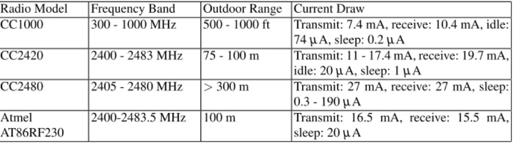
1.2.3.2 Radio Transceivers
The radio transceiver properties of each mote are as shown in Table 1.3. Most of the motes are equipped with 802.15.4 transceivers with slightly different characteristics on frequency band and outdoor range. One important difference is that these models support different number of power states, and each of the power states consumes various amount of power.
Radio Model Frequency Band Outdoor Range Current Draw
CC1000 300 - 1000 MHz 500 - 1000 ft Transmit: 7.4 mA, receive: 10.4 mA, idle: 74µA, sleep: 0.2µA
CC2420 2400 - 2483 MHz 75 - 100 m Transmit: 11 - 17.4 mA, receive: 19.7 mA, idle: 20µA, sleep: 1µA
CC2480 2405 - 2480 MHz >300 m Transmit: 27 mA, receive: 27 mA, sleep: 0.3 - 190µA
Atmel AT86RF230
2400-2483.5 MHz 100 m Transmit: 16.5 mA, receive: 15.5 mA, sleep: 20µA
1.2.3.3 Sensor Support
There are several types of sensors for detecting humidity, temperature, light, pres-sure, acceleration/seismic, acoustic, magnetic, video, vibration and other types of environment conditions. Motes are equipped with sensors in two ways, on-board sensors or plug-in sensors. Most of motes, such as Mica, Mica2, MicaZ, IRIS and so on, provide no on-board sensors. Instead, an expansion connector is provided for installing external sensor boards. As shown in Table 1.4, just a few sensor nodes, such as TelosB, provide on-board sensors.
Sensor Node Name Sensors
Mica / Sun SPOT Light, temperature, acceleration/seismic sensors MicaZ / Mica2 / EPIC /
IRIS / LOTUS / Cricket
Expansion connector for light, temperature, barometric pressure, accel-eration/seismic, acoustic, magnetic and other sensor boards
TelosB Optional integrated temperature, light and humidity sensor
Waspmote Expansion connector for gas, temperature, liquid level, weight, pres-sure, humidity, luminosity, accelerometer, soil moisture, solar radiation Table 1.4 Sensor Specification Comparison
1.3 The TinyOS Operating System
1.3.1 Introduction
TinyOS is a well-known and widely-used open source operating system designed for wireless sensor networks. It started as a project at UC Berkeley as part of the DARPA NEST program. Since it was made available to public in 2000, TinyOS has attracted thousands of academic and commercial developers and users worldwide.
1.3.2 System Overview
There are four requirements of wireless sensor networks that motivate the design of TinyOS:
• Limited Resources: Generally, the sensor nodes or motes have very limited hard-ware resources to achieve the goals of small size, low cost, and low power con-sumption.
• Reactive Concurrency: In wireless sensor networks, a sensor node must be able to respond to many types of events, such as sending and receiving packets.
Thefore, a concurrency management that reduces potential bugs while satisfying re-source and timing constraints is required.
• Flexibility: The variety of hardware and applications in sensor networks implies that the operating system for sensor nodes must be flexible. In addition, the op-erating system for sensor nodes should also support fine-grained modularity so that it can be customized and reused.
• Low Power Operations: To ensure prolonged operation lifetime, it is crucial to improve the energy efficiency of motes. Therefore, the low power operation is an important goal in the operating system design.
To achieve these four requirements, the design of TinyOS concentrates on two ba-sic principles: the event-driven programming model and the component-based sys-tem architecture. Specifically, TinyOS supports an event-driven concurrency model which consists of split-phase interfaces, asynchronous events, and tasks. TinyOS is implemented in the NesC programming language, a dialect of C, which supports the TinyOS concurrency model, as well as mechanisms for combining different soft-ware components together to form robust network embedded systems. The nesC programming language is designed to allow application developers to easily build different components and link them together to construct complete, concurrent sys-tems. This allows developers and users to enjoy enough flexibility to customize the system based on hardware and applications.
TinyOS is composed of a tiny scheduler and a graph of components. Each com-ponent is an independent computational unit that has one or more interfaces. These interfaces, which are bi-directional, provide the only point of access to the com-ponent. There are three computational abstractions for components: commands, events, and tasks.
Commands and events are designed for inter-component communication, while tasks are used to demonstrate intra-component concurrency. Typically, a command is a request sent to a component to perform some service, such as reading data from a sensor, while an event signals the completion of that service. Hardware interrupts or packet arrivals can also signal the events asynchronously. The command returns immediately while the event signals the completion of the service some time later.
Commands and events may post a task, which is a function that will be executed by TinyOS scheduler at a later time, rather than being executed immediately. Tasks are atomic with respect to each other and run to completion, though they can be preempted by events. Tasks can be used to call lower level commands, signal higher level events, and schedule other tasks which are within a component. The run-to-completion execution model of tasks makes it possible to allocate a single stack that is assigned to the currently executing task, which allows tasks to be much more lightweight compared to threads. A non-preemptive, FIFO scheduling policy is used in the standard TinyOS task scheduler.
1.3.3 Event based Concurrency Model
In wireless sensor network applications, fine-grained concurrency is needed, be-cause events can arrive at any time and must interact with ongoing computations. There are two approaches to solve this problem: 1) queueing the events on their ar-rival so that they could be executed later, as in most message-passing systems [5], and 2) executing an event handler immediately, also referred to as the active message approach [30]. TinyOS chooses the latter approach because some of those events are time critical.
The execution model of TinyOS is event-driven which consists of run-to-completion tasks which represent the ongoing computation, and interrupt handlers that are
in-voked asynchronously by hardware. A program uses thepostoperator to submit
a task to the scheduler for execution, and all tasks run to completion and the other tasks will not preempt the running task. Waiting tasks in the task queue will be ex-ecuted in the order of their arrivals. In other words, tasks are atomic with respect to each other. However, tasks are not atomic with respect to interrupt handlers, or the commands and events invoked by the interrupt handlers.
On one hand, the non-preemptive TinyOS concurrency model can provide pro-grammers a simple way to deal with the race conditions, deadlocks and other concurrency-related issues. On the other hand, it also can cause some serious prob-lems in many applications when long running tasks are involved. In these probprob-lems, even priority tasks may be delayed, which will reduce the responsiveness of the sys-tem significantly. The concurrency model of TinyOS makes TinyOS most suitable for developing simple, non time critical applications. Programmers may even can split large tasks into smaller pieces to handle the non-preemptive tasks problem, so that the maximum delay for incoming priority tasks will be reduced. However, as the computational capabilities of sensor nodes increase and their applications become more complex, this concurrency model may not be suitable in some scenarios.
1.3.4 Component based System Architecture
Another important concept of TinyOS’s programming model is the so called com-ponents which encapsulate a set of specific services, that are specified by interfaces. A general component structure is shown in Figure 1.1. The TinyOS component con-tains four interrelated parts: a set of command handlers, a set of event handlers, a fixed-size frame, and a set of simple tasks. Tasks, command and event handlers run in the context of the frame and operate on its state.
A component has two classes of interfaces: one consists of those the component provides and the other consists of those the component uses. Figure 1.2 shows a sim-plified form of the TimerM component (TimerM component is a part of the TinyOS timer service), which provides the StdControl and Timer interfaces and uses a Clock interface. Interfaces, which are bi-directional, contain both commands and events. The providers of an interface implement the commands while the users of an
inter-Command Handlers Set of Tasks
Event Handlers Frame (containing state information)
Fig. 1.1 The Structure of a TinyOS Component [15]
face implement the events. For instance, as shown in Figure 1.3, the timer interface
definesstart(),stop()commands and afired()event. Thestart()and
stop()commands are implemented in the component that provides this interface,
while thefired()event is implemented in the component that uses this interface.
module TimerM { provides {
interface StdControl; interface Timer[uint8_t id]; }
uses interface Clock; }
Implementation { … a dialect of c … }
Fig. 1.2 The TimerM Component [16]
In nesC, there are two types of components: modules and configurations. As shown in Figure 1.2, modules are written in a dialect of C and used to call and im-plement commands and events. A module declares private state variables and data
interface StdControl { command result_t init(); command result_t start(); command result_t stop(); }
interface Timer {
command result_t start(char type, uint32_t interval); command result_t stop();
event result_t fired(); }
interface Clock {
command result_t setRate(char interval, char scale); event result_t fire();
}
Interface SendMsg {
command result_t send(uint16_t address, uint8_t length, TOS_MsgPtr msg); event result_t sendDone(TOS_MsgPtr msg, result_t success); }
Fig. 1.3 TinyOS Interface Example [16]
buffers, which can only be referenced by itself. Configurations are used to wire dif-ferent components together through interfaces of these components. For instance, as shown in Figure 1.4, the TinyOS timer service is a configuration (TimerC) that ties the timer module (TimerM) and the hardware clock component (HWClock) together. Multiple component can be aggregated together into a single “supercom-ponent” through configurations.
configuration TimerC { provides {
interface StdControl; interface Timer[uint8_t id]; }
}
Implementation {
components TimerM, HWClock;
StdControl = TimerM.StdControl; Timer = TimerM.Timer; TimerM.Clk -> HWClock.Clock; }
NesC not only provides the component programming model, but also imposes some limitations on C to improve the efficiency and robustness of the source code. First, the function pointers are prohibited in nesC which allows the compiler to know the call graph of a program precisely. The benefit of this is cross-component opti-mizations for entire call paths become possible, which can help remove the overhead of cross-module calls and the inline code for small components into its callers. Sec-ond, nesC does not support dynamic memory allocation, which prevents memory fragmentation and runtime allocation failures.
1.3.5 Networking Architecture
The communication and networking architecture of TinyOS is based on Active Mes-sages (AM), which is a simple, extensible paradigm for message-based communi-cations. Each Active Message consists of two parts: the name of a user-level handler which will be invoked on a target node and a data payload which will be passed as arguments. Specifically, in TinyOS, the packets of the active message are 36 bytes long and the handler ID is 1 byte. As an active message is received, the node dis-patches the message to one or more handlers that are registered to receive messages of that type. Figure 1.5 shows the complete component graph of an ad-hoc network-ing application which is based on the active message model in TinyOS.
Ad Hoc Routing Application
Active Messages
Radio Packet Serial Packet
Radio Byte UART
RFM application application message message packet packet byte byte bit bit photo clocks SW SW HW HW
Fig. 1.5 Ad-Hoc Networking Application Component Graph [30]
The components underlying the packet level is used to transmit the block of bytes out over the radio. The interface of the packet level component provides a mecha-nism to initiate the transmission, and when a transmission or a reception is complete two events will be fired. In Figure 1.5 we can see AM not only provides an unre-liable, single-hop datagram protocol, but also a unified communication interface to
the radio and the serial port. The application level protocols which are built on top of the AM interface provide multihop communication, large ADUs, or other features.
1.3.6 New Features in TinyOS 2.x
TinyOS 2.x can be regarded as a clean slate redesign and re-implementation of TinyOS. The motivation for developing TinyOS 2.x is to eliminate several limita-tions in TinyOS 1.x which make 1.x hard to meet nowadays requirements and uses. For instance, the fundamental limitations of the structure and interfaces defined in TinyOS 1.x, cause the following problems: components are tightly coupled, inter-actions are hard to find, and it is difficult for a newcomer to learn sensor network programming quickly. The main modifications and new features of TinyOS 2.x lie in the following aspects.
1.3.6.1 Hardware Abstraction
To implement the hardware abstractions, TinyOS 2.x follows a three-level abstrac-tion hierarchy, called the HAA (Hardware Abstracabstrac-tion Architecture) shown in Fig-ure 1.6. HPL2 HAL2 HIL2 HPL1 HAL1 HIL1 HPL4 HAL4 HIL4 HPL3 HAL3 HIL3
HW Platform 1 HW Platform 2 HW Platform 3 HW Platform 4 Platform-specific Applications Platform-specific Applications Cross-platform Applications HW/SW Boundary HW/SW Boundary H ar d w ar e In d e p e n d e n ce H ar d w ar e In d e p e n d e n ce
Fig. 1.6 Hardware Abstraction Architecture for TinyOS 2.x [1]
At the bottom of the HAA is the HPL (Hardware Presentation Layer), which is a thin software layer on top of the raw hardware. HPL is used to present hardware such as IO pins or registers as nesC interfaces. Generally there is no state in the HPL besides the hardware itself, which has no variables.
At the middle of the HAA is the HAL (Hardware Abstraction Layer), which is built on top of the HPL. HAL provides higher-level abstractions that are easier to
use than the HPL. Though HAL provides high-level abstractions of hardware, it still provides the full functionality of the underlying hardware.
At the top of the HAA is the HIL (Hardware Independent Layer), which is built on top of the HAL. HIL provides abstractions that are hardware independent, which means that the HIL usually does not provide all of the functionality that the HAL does.
1.3.6.2 Scheduler
TinyOS 2.x scheduler also has a non-preemptive FIFO policy, but tasks in 2.x oper-ate slightly differently compare to those in 1.x. In TinyOS 2.x, tasks can have their own reserved slots in the task queue, and a task can only be posted once. A post fails if and only if the task has already been posted. If a component needs to post a task multiple times, an internal state variable can be set in the component, which means when the task executes, it can repost itself.
This slight change in semantics significantly simplifies the component code, be-cause a component can just post the task instead of testing to see if a task has already been posted. Components do not need to try to recover from failed posts with retries.
1.3.6.3 Multi-thread Support
TinyOS 1.x does not provide any multi-thread support, so that application develop-ment should strictly follow the event driven programming model. Since version 2.1, TinyOS provides support for multi-thread and these TinyOS threads are called TOS Threads [11]. The TOS thread package, which is backward compatible with exist-ing TinyOS code, provides a thread-based programmexist-ing model which is compatible with an event-driven kernel. In TinyOS, though application-level threads cannot pre-empt tasks and interrupt handlers, they can prepre-empt other application-level threads. The TinyOS scheduler is run by a high priority kernel thread which is dedicated to this task. Control Blocks (TCB) are dynamically allocated by TOS threads Thread with space for a fixed size stack that does not grow overtime. Context switches and system calls of TOS thread introduce an overhead which is less than 0.92% [11].
1.3.6.4 Booting/Initialization
TinyOS 2.x has a different boot sequence than TinyOS 1.x. The interface StdControl
in TinyOS 1.x has been split into two interfacesInitandStdControl. The latter
one only has two commandsstartandstop. In TinyOS 1.x, components will be
powered up and started at boot if they are wired to the boot sequence. However, in TinyOS 2.x this case will not happen, because the boot sequence only initializes components. When boot sequence finishes initializing the scheduler, hardware, and
software, it will signal theBoot.bootedevent. This event will be handled by the top-level application component which will start services accordingly.
1.3.6.5 Virtualization
The concept of a “generic” or instantiable component, which is introduced by nesC 1.2, allows TinyOS 2.x to have reusable data structures, like bit vectors and queues, which can make application development more simple and efficient. Furthermore, with the help of generic configurations, services can encapsulate complex wiring relationships for clients that need them, which means many basic TinyOS services now can be virtualized. A program can instantiate a service component that pro-vides the needed interface rather than wiring to a component with a parameterized interface (e.g., GenericComm or TimerC in 1.x).
1.3.7 Implementation and Hardware Support
TinyOS and its applications are very small, which are suitable for those platforms where hardware resources are often limited. TinyOS can run on a wide range of hardware platforms, including EPIC, Imote2, Shimmer, IRIS, Kmote (Telos Rev B), Micaz, Mica2, Mica2Dot, NXTMOTE (TinyOS on LEGO MINDSTORMS NXT), Mulle, TMote Sky (Telos Rev B), TinyNode, Zolertia Z1, UCMini, among others. Supported microcontrollers include Atmel AT90L-series, Atmel ATmega-series, Texas Instruments MSP-series and Intel XScale PXA271. The details of these hardware platforms can be found in section 1.2.
1.4 Contiki: A Lightweight and Flexible Operating System
1.4.1 Introduction
Developed by the Swedish Institute of Computer Science, Contiki is a lightweight and flexible operating system for WSNs. Contiki provides dynamic loading and unloading of individual components and services. Although it implements an event-driven kernel, it also supports preemptive multi-threading, which is implemented as a library that is linked only with programs that explicitly require multi-threading support.
In the following subsections, we present the system overview, kernel architecture, and key features of the Contiki operating system.
1.4.2 System Overview
Contiki is an operating system developed for sensor motes with constrained re-sources. A running Contiki system is composed of four components: the kernel, the libraries, the program loader, and a set of processes. As shown in Figure 1.7, the memory of Contiki is separated into two parts at the compile time: the core and the loaded program. The Contiki kernel, the program loader, the language run-time, support libraries, and a communication stack with device drivers for the communi-cation hardware are saved in the core. On the other hand, programs are loaded into the system by program loaders.
Loaded program Communication service Language run-time Program loader Kernel ROM RAM Loaded program Communication service Kernel Core Core
Fig. 1.7 Contiki as Partitioned into Core and Loaded Programs [22]
Prior to the deployment of the system, the core is compiled into a single binary image and stored in the memory. After the deployment, the core is not modified, unless a special boot loader is used to overwrite or patch the core. In the program loader, programs binaries may be obtained either by using the communication stack, or by using external storage such as EEPROM. In most cases, programs loaded into the system are first stored in EEPROM before being programmed into the code memory.
Saved in the core, the kernel controls the communication between processes. This functionality is not implemented by providing a hardware abstraction layer as is the case with TinyOS, but by letting device drivers and applications communicate directly in the hardware. A process, which is controlled by kernel, can be either an application program or a service. As mentioned above, the programs are loaded by the program loader. On the other hand, a service is a set of application processes working together to implement a specific functionality. Both the application pro-grams and services, can be dynamically replaced in-time. A process is defined by an event handler function and an optional poll handler function, where the event handler is an asynchronous callback subroutine that handles inputs received in a program, and a poll handler specifies an action when a process is polled. The state
of the process is kept in its private memory and the kernel only keeps a pointer to the process state.
More specifically, the kernel provides a lightweight event scheduler and a polling mechanism. The event scheduler is in charge of dispatching events to run processes and periodically calls processes’ polling handlers, which specifies the action of the polled process. Once an event handler is scheduled, the kernel can not preempt it. In that case, event handlers must run to completion, if no internal mechanisms are used to achieve preemption. On the other hand, the polling mechanism specifies high priority events that are scheduled in-between each asynchronous event. Polling mechanism is used by processes that operate near the hardware to check for status updates of hardware devices. All processes that implement a poll handler are called in order of their priority, when a poll is scheduled.
Contiki uses a two level scheduling hierarchy to implement the event preemption. First, in Contiki, all event scheduling is done at a single level and events cannot preempt each other, unless there is an interrupt. An interrupt can be implemented by using hardware interrupts or underlying real-time execution support. In Contiki, the interrupts are never disabled. In that case, Contiki does not allow events to be posted by interrupt handlers to avoid race conditions in the event handler. Instead, a polling flag, which provides interrupt handlers with a way to request immediate polling, is provided in the kernel to request a poll event.
The events, which triggers the execution of programs, can be dispatched by the kernel or through the polling mechanism. There are two types of events supported in Contiki kernel, asynchronous events and synchronous events. Asynchronous events are a form of deferred procedure calls, which are enqueued by the kernel and are dispatched to the target process some time later. The use of asynchronous events reduce stack space requirement, because the stack is rewound between each invo-cation of event handler. However, in order to implement a immediate schedule of target processes, synchronous events are supported, too.
1.4.3 Key features
As we mentioned above, Contiki is a lightweight event-driven operating systems that supports both preemptive multi-threading and dynamic loading and unloading of individual components and services. In this section, we will introduce how Contiki implements those features in detail.
1.4.3.1 Easy Event Driven Programming
In general, Contiki is an event-driven operating system. This is because event-driven systems do not need to allocate memory for per-thread stacks, which leads to lower memory requirements. As an operating system designed for sensor motes with con-strained resource, it is important to keep the system to be lightweight.
However, as we discussed earlier, event-based programming is typically compli-cated, as an event-driven model does not support blocking wait, an abstraction that is usually desired to express the program logic flows. In that case, programmers of such systems frequently need to use state machines to implement control flow for high-level logic that cannot be expressed as a single event handler. To cope with this problem, a novel programming abstraction called Protothreads [21] is proposed for Contiki. Protothreads, which provide a conditional blocking wait operation, can be used to reduce the number of explicit state machines in event-driven programs, and make it possible to write event-driven programs in a thread-like style with a memory overhead of only two bytes per protothread.
From the view of implementation, in Contiki operating system, processes are implemented as protothreads running on top of the event-driven kernel. The pro-tothreads mechanism does not specify how to invoke or schedule a protothread. Instead of that, the system using the protothread defines all these. In general, the protothread of a process is invoked when the process receives an event, such as a message from another process, a timer, or a sensor input. The blocking of the thread is executed while the process receives an event using the protothread con-ditional blocking statements. We can treat protothreads as a combination of events and threads. From threads, blocking wait semantics have been inherited by pro-tothreads. From events, protothreads have inherited the stacklessness and the low memory overhead. The linear sequencing of statements in event-driven programs is supported by the blocking wait semantics. As a protothread does not require its own stack, protothreads are very lightweight compare to traditional threads. Be-sides, all protothreads run on the same stack, and context switching is done by stack rewinding. These two features make protothread work better on memory constrained systems.
More specifically speaking, protothreads can be used to replace state machines. The steps of doing this are as following. In general, the control flow of a state ma-chine can be decomposed to three primitive patterns: sequences, iterations and se-lections as shown in Figure 1.8. All these three patterns can be easily mapped to protothreads as shown in Figure 1.9. In that case, to rewrite an event driven state machine with protothreads, we just need to first find the patterns in the state ma-chine, then translate the patterns to corresponding protothreads.
a) cond1 b) cond2 c) condition cond2a cond1 cond2b
a_sequence: PT BEGIN an_iteration: PT_BEGIN (*…*) a_selection: PT_BEGIN (*…*) if( diti ) _ (*…*) PT_WAIT_UNTIL(cond1) (*…*) PT END ( ) while(cond1) PT_WAIT_UNTIL(cond1 orcond2) (* *) if(condition) PT_WAIT_UNTIL(cond2a) else PT_WAIT_UNTIL(cond2b) PT_END (*…*) PT_END _ _ ( ) (*…*) PT_END
Fig. 1.9 Pseudocode of Protothreads for Different State Machine Transitions [21].
Based on the pseudocode in Figure 1.9, we have already had a peak on how to program on protothread. Let us have look at the details on this in the following part. In general, there are a set of APIs been provided by Protothreads:
1. PT BEGIN(pt): begins the protothread. 2. PT END(pt): ends the protothread. 3. PT INIT(pt): initializes the protothread. 4. PT EXIT(pt): exits from protothread.
5. PT WAIT UNTIL(pt, condition): the operation takes a conditional statement and blocks the protothread until the statement evaluates to be true.
6. PT YIELD(pt): performs a single unconditional blocking wait that temporarily blocks the protothread until the next time the protothread is invoked.
7. PT SPAWN(pt): initializes a child protothread and blocks the current pro-tothread until the child propro-tothread is either ended with PT END or exited with PT EXIT.
The functionality of each API is as following. The beginning and end of a pro-tothread are declared with PT BEGIN and PT END statements. Other propro-tothread statements, such as PT WAIT UNTIL, must be placed between PT BEGIN and PT END. A protothread can exit prematurely with a PT EXIT statement. A pro-tothread is stackless, because instead of having a history of function invocations, all protothreads in a system run on the same stack that can be rewound. In that case, protothread can only block at the top level of the function. In other words, it is im-possible for regular function called from a protothread to block inside the called function, unless an explicit PT WIAT UNTIL() statement is used. As a result of that, the programmer should always be aware of which statements may block the thread.
Let us take the code for hypothetical MAC protocol as an example to see how to translate the code of state machines to protothreads. In general, the hypothetical MAC works as following: turn on the radio at t0; wait untilt =t0+tawake; turn
radio off, if all communication has completed; if communication has not completed, wait until it has completed ort=t0+tawake+twaitmax; turn radio off, and wait until
The above steps can be generalized as the state machine shown in Figure 1.10. On the other hand, the pseudocode for the state machine and the protothreads are shown in Figure 1.11. From the pseudocode, we can see that protothreads not only make the programming simple, but also considerably decrease the code size.
ON
Timer expired
WAITING
OFF
Timer expired
Timer expired
Remaining communication
Fig. 1.10 State Machine of the Hypothetical MAC Protocol [21].
State: {ON, WAITING, OFF} radio_wake_eventhandler: if(state = ON) radio_wake_protothread: PT BEGIN if (state ON) if(expired(timer)) mer ← tsleep if (notcommunication_complete()) PT_BEGIN while (true) radio_on() timer ← tawake state ← WAITING wait_timer← twait_max else radio off() PT_WAIT_UNTIL(expired(timer)) mer ← tsleep if (notcommunication_complete()) wait timer←t it radio_off() state ← OFF elseif(state = WAITING) if (communication_complete() or d( )) wait_timer← twait_max PT_WAIT_UNTIL( communication_complete() or expired(wait_timer)) d ff() expired(wait_timer)) state ← OFF radio_off()
elseif(state = OFF)
radio_off()
PT_WAIT_UNTIL(expired(timer))
PT_END elseif(state OFF)
if(expired(timer)) radio_on() state ← ON
← mer ← tawake
Fig. 1.11 Pseudocode of the Hypothetical MAC Protocol with States (left) and Protothreads (right) [21].
1.4.3.2 Preemptive Multi-Threading
As mentioned above, Contiki is an event-driven operating system that supports preemptive threading. In this section, we will show how preemptive multi-threading is implemented in details.
In general, preemptive multi-threading is implemented on top of the event-based kernel as a library that can be linked on demand. More specifically, only applications that explicitly require a multi-threaded model will be linked with this library.
The multi-threading in Contiki is designed as following: each thread requires a separate stack, and threads execute on their own stack until they explicitly yield or are preempted. In that case, the multi-threading library is divided into two parts: a platform independent part that provides interfaces to the event-based kernel, and a platform specific part which implements the stack switching and preemption prim-itives between threads. The preemption is implemented by using a timer interrupt that saves the processor registers onto the stack and switches back to the kernel stack.
As a loadable library, a set of stack management functions are provided. We hide the details of the internal code of each functions, and only show the APIs of the library here as following:
1. mt yield(): yield from the running thread.
2. mt post(id, event, dataptr): post an event from the running thread.
3. mt wait(event, dataptr): wait for an event to be posted to the running thread. 4. mt exit(): exit the running thread.
5. mt start(thread, functionptr, dataptr): start a thread with a specified function call.
6. mt exec(thread): execute the specified thread until it yields or is preempted.
In the APIs above,mt yield(),mt post(),mt wait(), andmt exit()
can be called from a running thread. On the other hand,mt start()andmt exec()
are called to set up and run a thread. The actual scheduling of a thread is performed
inmt exec(), which needs to be called from an event handler.
1.4.3.3 Run-Time Dynamic Linking
The third feature of Contiki is dynamic loading and unloading of individual com-ponents and services. This is because of the following reason. In a variety range of situations, it is necessary to update system software for sensor networks. In most of these scenarios, just a small part of the system needs to be modified. Without sup-port for dynamic loading and unloading of system components, it is costly to per-form those changes. In that case, being able to dynamically reprogram parts of the sensor network system, instead of reloading the whole system image, helps shorten the development cycle time distinctly.
The Contiki system uses loadable modules to perform dynamic reprogramming. With loadable modules, only parts of system need to be modified when a single program is changed. It works as following: the native machine code of the program that is loaded into the system, which holds references to functions or variables in the system, is contained in a loadable module. The references must be resolved to the physical address of the functions or variables before the machine code can be executed. The process of resolving the references is called linking. There are two
ways to link modules, the pre-linked modules and the dynamically linked modules. The first way is done when the module is compiled. It contains the absolute physical addresses of the referenced functions or variables. On the other hand, the second way is done when the module is loaded, and it contains the symbolic names of all system core functions or variables that are referenced in the module.
The original Contiki [22] uses pre-linked binary modules for dynamic loading. Compare to dynamically linked modules, pre-linked modules have two benefits: first, pre-linked modules are smaller than dynamically linked modules, hence less information needs to be transmitted. Second, the process of loading a pre-linked module into the system is less complex than the process of linking a dynamically linked module. In that case, the pre-linked method has smaller run-time overhead than dynamically linked method. However, the pre-linked module needs to keep the absolute addresses of all functions and variables that are referenced by the module, which means that these physical addresses are hard-coded. Therefore, the pre-linked module can only be loaded into the system with the exact same physical addresses as the original system.
In the later versions of Contiki, a dynamic linker is proposed and implemented [23]. The dynamic linker is designed to link, relocate, and load the standard object files, such as Executable and Linkable Format (ELF), Compact ELF (CELF), and so on. It takes four steps to link, relocate and load the object files: first, the dynamic linker parses the object files and extracts relevant information about where in the object files the code, data, symbol table, and relocation entries are stored. Secondly, mem-ory for the code and data is allocated in flash ROM and RAM, respectively. After that, the code and data segments are linked and relocated to their respective memory locations. Finally, the code is written to flash ROM and the data to RAM.
1.4.3.4 Callable Services
To make the dynamic loading and unloading of a set of applications easier, Con-tiki proposed the fourth feature, callable services. In ConCon-tiki, the functionalities that the application processes may call are implemented as services. A service can be seen as a form of shared library. The most typical services include communication protocol stacks, sensor device drivers, and higher level functionalities such as sen-sor data handling algorithms. In Contiki, services can be dynamically replaced and dynamically linked at run-time.
As shown in Figure 1.12, services are managed by aservice layer, which sits next to the kernel. The service layer keeps track of running services and finds installed services. Services can be identified by strings of text that describe them. In that case, the installed services are searched with those strings. A typical service consists of a service interface and a process that implements the interface. The service interface consists of a version number and a function table, which holds function pointers to the functions implementing the interface.
Services can be dynamically loaded and replaced at run-time. When a service is to be replaced, the kernel informs the running version of the service by posting a
special event to the service process. With the help of the kernel, a pointer to the new service process is provided, and the service can produce a state description that is then passed to the new process. Besides that, a version number of the new service is tagged to the service state description, so that only one compatible version of the same service will be loaded. Meanwhile, the old service removes itself from the system. Application process Function 1(); Function 2(); Function 3(); Service layer Service interface stub Kernel Version number Function 1 ptr Function 2 ptr Function 3 ptr
Service interface Service process Function 1 implementation Function 3 implementation Function 2 implementation
Fig. 1.12 How an Application Process Calls a Service [22].
1.4.4 Network Protocols
Besides the basic services provided by the operating system, two extended com-ponents on network protocols have been proposed for Contiki. In this section, we introduce them in details.
1.4.4.1 ContikiRPL
RPL (Routing Protocol for Low-power and Lossy Networks) is a standard protocol for IPv6 routing over Low-power, Lossy Networks (LLNs). Optimized for many-to-one traffic pattern, RPL is designed for networks with significantly higher packet loss rates than traditional IP routing protocols. The network topology of RPL is a Destination-Oriented Directed Acyclic Graph (DODAG) rooted at a border router, where all nodes in the network maintain a route to the router.
In Contiki, a variant of RPL called ContikiRPL [2], is proposed. ContikiRPL sets up forwarding tables only and leaves the actual packet forwarding to other net-work layers, instead of making forwarding decisions per packet. ContikiRPL gets link cost estimated by an external neighbor information module, and recomputes the path cost to the sink via the updated link, and checks if there is a need to change pre-ferred parents on the forwarding table. The link cost is computed as an exponentially
weighted moving average function over the number of link layer transmissions, and the neighbor with smallest cost will be kept in the forwarding table.
1.4.4.2 ContikiMAC
Contiki group proposed a MAC layer protocol called ContikiMAC [24], which uses a power-efficient wake-up mechanism with a set of timing constraints to allow devices to keep their transceivers off. In general, ContikiMAC is a simple asyn-chronous protocol, which needs no signaling messages and additional packet head-ers.
ContikiMAC is a radio duty cycling protocol that uses periodical wake-ups to listen for packet transmissions from the neighbors. For a sender, it repeatedly sends a packet, until it gets the acknowledgment from the receiver. For a receiver, it pe-riodically wakes up to check if there is a packet sent to it. If the receiver detects a transmission to it, it should stay awake to receive the full packet and transmit a link layer acknowledgment. For other nodes that detect the packet, they go to sleep immediately. The sender can learn the wake-up time of a receiver based on the time it gets the acknowledgment. In that case, more power can be saved while the sender keeps on sleeping until the time receiver wakes up.
1.4.5 Implementation and Hardware Support
The code size of Contiki, which is tightly related with the provided services, is larger than the code size of TinyOS. As a set of services are provided, Contiki’s event kernel is significantly larger than that of TinyOS. Compared to TinyOS, whose event kernel only provides a FIFO event queue scheduler, the Contiki kernel is more complex, as both FIFO events and poll handlers with priorities are supported. On the other hand, the dynamic loading and unloading property of Contiki requires more run-time code than TinyOS.
Contiki is ported onto a number of architectures, such as Texas Instruments MSP430, Atmel AVR, Hitachi SH3 and the Zilog Z80. In that case, it can run in a large range of hardware platforms, such as Mica, Mica2, MicaZ, EPIC, IRIS, Sun SPOT, LOTUS, TelosB, Cricket, and Waspmote mentioned in section 1.2.
LiteShell
User Environment File System (LiteFS)
User control Sensor Node Neighborhood LiteOS Kernel Sensor node Device Drivers Data Files User Applications Multi-threaded Kernel Binary Installer System Calls Services Command Processor Session State Data Cache
Fig. 1.13 LiteOS Operating System Architecture [29]
1.5 The LiteOS Operating System
1.5.1 Introduction
The LiteOS operating system is a multi-threaded operating system that provides Unix-like abstractions for WSNs. Aiming to be an easy-to-use platform, LiteOS offers a number of novel features, including: (1) a hierarchical file system and a wireless shell interface for user interaction using UNIX-like commands; (2) kernel support for dynamic loading and native execution of multithreaded applications; and (3) online debugging, dynamic memory, and file system assisted communication stacks. LiteOS also supports software updates through a separation between the kernel and user applications, which are bridged through a suite of system calls.
The key contribution of LiteOS is that it presents a familiar, Unix-like abstrac-tion for WSNs by leveraging the likely existing knowledge that common system programmers already have: Unix, threads, and C. By mapping sensor networks to file directories, it allows applying user-friendly operations, such as file directory commands, to sensor networks, therefore reducing the learning curve for operating and programming sensor networks.
1.5.2 System Overview
In this section, we first present an overview of the LiteOS operating system, then present its three subsystems.
1.5.3 Architectural Overview
Figure 1.13 shows the overall architecture of the LiteOS operating system, parti-tioned into three subsystems: LiteShell, LiteFS, and the kernel. Implemented on the base station PC side, the LiteShell subsystem interacts with sensor nodes only when a user is present. Therefore, LiteShell and LiteFS are connected with a dashed line in this figure.
LiteOS provides a wirelessnode mounting mechanism (to use a UNIX term)
through a file system called LiteFS. Much like connecting a USB drive, a LiteOS node mounts itself wirelessly to the root filesystem of a nearby base station. More-over, analogously to connecting a USB device (which implies that the device has to be less than a USB-cable-length away), the wireless mount currently supports devices within wireless range. The mount mechanism comes handy, for example, in the lab, when a developer might want to interact temporarily with a set of nodes on a table-top before deployment. Ideally, a network mount would allow mounting a device as long as a network path existed either via the Internet or via multi-hop wireless communication through the sensor network. Once mounted, a LiteOS node looks like afile directoryfrom the base station. A sensor network, therefore, maps into a higher level directory composed of node-mapped directories. The shell, called LiteShell, supports UNIX commands, such as copy (cp), executed on such directo-ries.
1.5.4 Key Features
1.5.4.1 LiteShell Subsystem
Table 1.5 The List of LiteOS Shell Commands Command List
File Commands ls, cd, cp, rm, mkdir, touch, pwd, du, chmod Process Commands ps, kill, exec
Debugging Commands debug, list, print, set
breakpoint, continue, snapshot, restore Environment Commands history, who, man, echo
Device Commands ./DEVICENAME
The LiteShell subsystem provides Unix-like command-line interface to sensor nodes. This shell runs on the base station PC side. Therefore, it is a front-end that interacts with the user. The motes do not maintain command-specific state, and only respond to translated messages (represented by compressed tokens) from the shell, which are sufficiently simple to parse. Such an asymmetric design choice not only significantly reduces the code footprint of the LiteOS kernel that runs on motes, but
also allows us to easily extend the shell with more complicated commands, such as authentication and security.
Currently, LiteOS supports the list of commands listed in Table 1.5. They fall into five categories: file commands, process commands, debugging commands, en-vironment commands, and device commands.
File Operation Commands
File commands generally maintain their Unix meanings. For example, thels
com-mand lists directory contents. It supports a-loption to display detailed file informa-tion, such as type, size, and protection. To reduce system overhead, LiteOS does not provide any time synchronization service, which is not needed by every application.
Hence, there is no time information listed. As an example, als -l command may
return the following:
$ ls -l
Name Type Size Protection
usrfile file 100 rwxrwxrwx
usrdir dir ---
rwxrwx---In this example, there are two files in the current directory (a directory is also a file):usrfileandusrdir. LiteOS enforces a simple multilevel access control scheme. All users are classified into three levels, from 0 to 2, and 2 is the highest level. Each level is represented by three bits, stored on sensor nodes. For instance, theusrdir directory can be read or written by users with levels 1 and 2.
Once sensor nodes are mounted, a user uses the above commands to navigate the different directories (nodes) as if they are local. Some common tasks can be greatly
simplified. For example, by using thecpcommand, a user can either copy a file
from the base to a node to achieve wireless download, or from a node to the base to retrieve data results. The remaining file operation commands are intuitive. Since LiteFS supports a hierarchical file system, it providesmkdir,rmandcdcommands.
Process Operation Commands
LiteOS has a multithreaded kernel to run applications as threads concurrently. LiteShell provides three commands to control thread behavior:ps,exec, andkill.
We illustrate these commands through an application called Blink, which blinks
LEDs periodically. Suppose that this application has been compiled into a binary file called Blink.lhex1, and is located under the C drive of the user’s laptop. To
install it on a node namednode101(that maps to a directory with the same name)
in a sensor network namedsn01, the user may use the following commands:
$ pwd
Current directory is /sn01/node101/apps
$ cp /c/Blink.lhex Blink.lhex Copy complete
$ exec Blink.lhex
File Blink.lhex successfully started $ ps
1LiteOS uses a revised version of the Intel hex format, called lhex, to store binary applications.

![Fig. 1.1 The Structure of a TinyOS Component [15]](https://thumb-us.123doks.com/thumbv2/123dok_us/10295803.2937460/14.918.289.606.136.413/fig-structure-tinyos-component.webp)
![Fig. 1.4 TimerC Configuration [16]](https://thumb-us.123doks.com/thumbv2/123dok_us/10295803.2937460/15.918.298.621.674.873/fig-timerc-configuration.webp)
![Fig. 1.5 Ad-Hoc Networking Application Component Graph [30]](https://thumb-us.123doks.com/thumbv2/123dok_us/10295803.2937460/16.918.240.682.574.797/fig-ad-hoc-networking-application-component-graph.webp)
![Fig. 1.6 Hardware Abstraction Architecture for TinyOS 2.x [1]](https://thumb-us.123doks.com/thumbv2/123dok_us/10295803.2937460/17.918.227.674.575.775/fig-hardware-abstraction-architecture-tinyos-x.webp)
![Fig. 1.7 Contiki as Partitioned into Core and Loaded Programs [22]](https://thumb-us.123doks.com/thumbv2/123dok_us/10295803.2937460/20.918.282.625.362.565/fig-contiki-partitioned-core-loaded-programs.webp)
![Fig. 1.9 Pseudocode of Protothreads for Different State Machine Transitions [21].](https://thumb-us.123doks.com/thumbv2/123dok_us/10295803.2937460/23.918.208.696.118.295/fig-pseudocode-protothreads-different-state-machine-transitions.webp)
![Fig. 1.11 Pseudocode of the Hypothetical MAC Protocol with States (left) and Protothreads (right) [21].](https://thumb-us.123doks.com/thumbv2/123dok_us/10295803.2937460/24.918.216.687.461.759/fig-pseudocode-hypothetical-mac-protocol-states-protothreads-right.webp)
![Fig. 1.12 How an Application Process Calls a Service [22].](https://thumb-us.123doks.com/thumbv2/123dok_us/10295803.2937460/27.918.258.642.287.456/fig-application-process-calls-service.webp)
